DIY solenoid motor
Have a good time everyone. In this article we will look at how the author made a solenoid motor with his own hands.
For the solenoid, the author took a piece from a telescopic radio antenna.
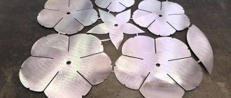
Two washers are the right size.
I put the washers on the antenna and fixed them with super glue.
Then the author took an insulated copper wire approximately 20 m long and wound it in one direction around the solenoid body. Next, the author will make a solenoid rod from a regular nail of suitable diameter. The rod should move freely in the tube.
Next, he measures and cuts off the excess.
Then the author takes the body of a ballpoint pen and marks it and cuts off the excess. Places this piece from the handle onto the stem and glues it with glue.
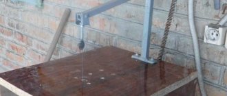
Then he makes a through hole in this tube.
Next, parallel to the hole, the author cuts a groove. Checks.
Then he takes a small wooden block with pre-drilled holes along the edges.
And attaches the solenoid to the block using plastic clamps (ties.) Cuts off the excess ends.
Then the author will make a crank mechanism. To do this, he will take a thick copper wire, remove the insulation from it and bend it as shown in the picture below. Then he will take another piece of the same wire and make a connecting rod from it. Like this. Next, install the connecting rod in its place, putting pieces of cambrics on both sides of the connecting rod to limit the movement of the connecting rod from side to side. The author took a piece of board as the base.
And the author made two identical bars in them with one hole each. The author will use them as support posts for the shaft.
I installed the shaft on the stands, tried it on and glued it. Then I limited the axial movement of the shaft using pieces of cambric.
On one side of the shaft, the author placed a flywheel previously carved from wood.
He then connected the connecting rod to the solenoid. Then I measured the required distance and glued the solenoid.
Next, he took a piece of copper wire with a slightly smaller diameter than he used for the connecting rod.
And first he made permanent motor contacts from it.
And then the control contact. Then the author has a check. Next, the author connects the solenoid to the contacts.
Well, the author has a solenoid motor ready. And now a test from the author. The author used a battery from a screwdriver as power supply.
And connects using alligator clips for wires. As we all see, everything works fine for the author.
Homemade video:
Source Delivery of new homemade products to the post office
Receive a selection of new homemade products by email. No spam, only useful ideas!
*By filling out the form you agree to the processing of personal data
Become the author of the site, publish your own articles, descriptions of homemade products and pay for the text. Read more here. usamodelkina.ru
How to make a solenoid motor
Content:
Modern engineers regularly conduct experiments to create devices with unconventional and non-standard designs, such as, for example, a rotation apparatus using neodymium magnets. Among these mechanisms, it is worth noting the solenoid motor, which converts the energy of electric current into mechanical energy. Solenoid motors can consist of one or more coils - solenoids. In the first case, only one coil is involved, when turning it on and off, mechanical movement of the crank mechanism occurs. The second option uses several coils that are switched on alternately using valves when current is supplied from the power source during one of the half-cycles of the sinusoidal voltage. The reciprocating motion of the cores drives the wheel or crankshaft. Solenoid motor working principleAccording to the basic classification, solenoid motors are resonant and non-resonant. In turn, there are single-coil and multi-coil designs of non-resonant motors. Parametric motors are also known in which the core is pulled into the solenoid, but takes the desired position when magnetic equilibrium is achieved after several oscillations. When the network frequency coincides with the natural vibrations of the core, resonance can occur. Solenoid motors are compact and simple in design. Among the disadvantages, it should be noted the low efficiency of these devices and the high speed of movement. To date, these shortcomings have not been overcome, so these mechanisms have not been widely used in practice. The operating coil of single-coil devices is turned on and off using a mechanical switch, due to the action of the core body, or a semiconductor valve. In both options, the reverse motion is ensured by a spring with elasticity. In engines with several coils, the working elements are turned on only by valves, when current is supplied to each coil in turn during one of the half-cycles of the sinusoidal voltage. The coil cores begin to retract one by one, as a result, this leads to reciprocating movements. These movements are transmitted through drives to various motors that perform the function of actuators. Solenoid motor designThere are various types of mechanical and electrical devices whose operation is based on the conversion of one type of energy into another. Their main types are widely used in all machines and mechanisms used in production and at home. There are also non-traditional devices, work on which is still carried out at the experimental level. These include solenoid motors that operate on the basis of the magnetic action of current. Its main advantage is the simplicity of design and availability of materials for manufacturing. The main element of this device is a coil through which electric current is passed. This leads to the formation of a magnetic field, which draws in a plunger made in the form of a steel core. Next, with the help of a crank mechanism, the translational movements of the core are converted into rotational movement of the shaft. You can use any number of coils, however, the most optimal option is considered to be one with two elements. All these factors must be taken into account when deciding how to make a solenoid motor with your own hands from scrap materials. An option with three coils, which has a more complex design, is often considered. However, it has more power and runs much smoother without requiring a flywheel for smooth operation. The operation of this device is as follows.
DIY solenoid motorThe best material for reels is considered to be textolite or hardwood. For winding, PEL-1 wire with a diameter of 0.2-0.3 mm is used. Winding is carried out in an amount of 8-10 thousand turns, ensuring the resistance of each coil is within 200-400 Ohms. After winding every 500 turns, thin paper spacers are made, and so on until the frame is completely filled. Mild steel is used to make the plunger. Cranks can be made from bicycle spokes. The upper head must be made in the form of a small ring-shaped ear with the required internal diameter. The lower head is equipped with a special grip for mounting on the crankshaft journal. It is made of two tin strips and is a fork that fits onto the crank neck. The final fastening of the plug is carried out with copper wire threaded through the holes. The connecting rod fork is put on a bushing made of copper, bronze or brass tube. The crankshaft is made of a metal rod. Its cranks are located at an angle of 120 degrees relative to each other. A power distributor is mounted on one side of the crankshaft, and on the other, a flywheel in the form of a pulley with a groove for the drive belt. To make a current distributor, you can use a brass ring or a piece of tube of suitable diameter. It turns out one whole ring and three half rings, located in relation to each other with a shift of 120 degrees. Brushes are made from spring plates or slightly riveted steel wire. The current distributor bushing is mounted on a textolite roller, placed on one of the ends of the crankshaft. All fastenings are carried out using BF glue and dowels made from thin wire or needles. The distributor is installed in such a way that the first coil is turned on when the plunger is in the lowest position. If the wires going from the coils to the brushes are swapped, the shaft will rotate in the opposite direction. The coils are installed in a vertical position. They are secured in different ways, for example, with wooden planks, which have recesses for the coil housings. Side panels made of plywood or sheet metal are attached to the edges, which provide space for installing bearings under the crankshaft or brass bushings. If there are metal sidewalls, the bushings or bearings are secured by soldering. It is recommended to install bearings in the middle part of the crankshaft. For this purpose, special tin or wooden racks are provided. To avoid the crankshaft shifting in one direction or another, it is recommended to solder copper wire rings to its ends at a distance of approximately 0.5 mm from the bearings. The engine itself must be protected by a tin or plywood casing. Engine calculations are performed based on alternating electric current, voltage 220 volts. If necessary, the device can operate with direct current. If the mains voltage is only 127 volts, the number of turns of the coil should be reduced by 4-5 thousand turns, and the wire cross-section should be reduced to 0.4 mm. If assembled correctly, the power of the solenoid motor will average 30-50 W. How to make a solenoid motor at home |
electric-220.ru
How to make a simple electromagnet - step-by-step instructions with diagrams
Such a device is convenient because its operation is easy to control using electric current - changing the poles, changing the force of attraction. In some matters it becomes truly indispensable, and is often used as a constructive element of various homemade products. It’s not difficult to make a simple electromagnet with your own hands, especially since almost everything you need can be found in every home.
What you will need
- Any suitable sample made of iron (it is highly magnetic). This will be the core of the electromagnet.
- The wire is copper, always with insulation to prevent direct contact of the two metals. For a homemade electric magnet, the recommended cross-section is 0.5 (but not more than 1.0).
- DC source - battery, battery, power supply.
Additionally:
- Connecting wires for connecting an electromagnet.
- Soldering iron or electrical tape to secure contacts.
This is a general recommendation since the electromagnet is made for a specific purpose. Based on this, the components of the circuit are selected.
And if it is done at home, then there cannot be any standard - whatever is at hand will do.
For example, in relation to the first point, a nail, a lock shackle, or a piece of iron rod are often used as a core - the choice of options is huge.
Winding
The copper wire is carefully wound onto the core, turn by turn. With such scrupulousness, the efficiency of the electromagnet will be the maximum possible.
After the first “pass” along the iron sample, the wire is laid in a second layer, sometimes a third. It depends on how much power the device requires.
But the direction of winding must remain unchanged, otherwise the magnetic field will become “unbalanced”, and the electromagnet will hardly be able to attract anything to itself.
To understand the meaning of the ongoing processes, it is enough to remember the physics lessons from the high school course - moving electrons, the EMF they create, the direction of its rotation.
After winding is completed, the wire is cut so that the leads can be conveniently connected to the power source. If it's a battery, then directly. When using a power supply, battery or other device, you will need connecting wires.
What to consider
There are certain difficulties with the number of layers.
- As turns increase, reactance increases. This means that the current strength will begin to decrease, and the attraction will become weaker.
- On the other hand, increasing the current rating will cause the winding to heat up.
The operating principle of the electromagnet is described in detail in the following video:
Connection
- Cleaning the copper terminals. The wire is initially coated with several layers of varnish (depending on the brand), and it is known to be an insulator.
- Soldering copper and connecting wires. Although this is not essential, you can twist it by insulating it with a PVC pipe or adhesive tape.
- Fixing the second ends of the wires on the clamps. For example, the “crocodile” type. Such removable contacts will allow you to easily change the poles of the electromagnet, if necessary during its use.
Useful tips
- To make a powerful electromagnet, home craftsmen often use a coil from an MP (magnetic starter), relays, or contactors. They are available for both 220 and 380 V.
It is not difficult to select an iron core based on its internal cross-section. For ease of control, you need to include a rheostat (variable resistance) in the circuit. Accordingly, such an electric magnet is already connected to the outlet.
The force of attraction is regulated by changing the R chain.
- You can increase the power of an electromagnet by increasing the cross-section of the core. But only up to certain limits. And here you have to experiment.
- Before making an electric magnet, you need to make sure that the selected iron sample is suitable for this. The check is quite simple. Take a regular magnet; There are a lot of things in the house on such “suction cups”. If it attracts the part selected for the core, it can be used. If the result is negative or “weak,” it is better to look for another sample.
Making an electromagnet is quite simple. Everything else depends on the patience and ingenuity of the master. You may have to experiment to get what you need - with the supply voltage, wire cross-section, and so on. Any homemade product requires not only a creative approach, but also time. If you do not regret it, then an excellent result is guaranteed.
12 volt electromagnet
In this video lesson, the “E+M” channel talked about what an electromagnet is. He also showed how to make it by hand with a supply voltage of 12 volts and performed a series of experiments using it. Showed how to increase efficiency.
First, a little theory of history. In the early 19th century, Danish physicist Oersted discovered the connection between electricity and magnetism. A current passing through a conductor located next to the compass deflects its needle towards the conductor. This indicates the presence of a magnetic field around the conductor. It also turned out that if you wind a conductor into a coil, its magnetic properties will increase. In a coil of wire, the so-called solenoid, magnetic lines are formed, the same as in a permanent magnet.
Depending on which side we carry the coil to the compass, it will deviate in one direction or another. Since two poles have formed in the coil: north and south. It is possible to change the direction of electric current when the poles are reversed. For the experiment, the author of the channel wound 2 identical coils. The first coil is 260 turns, resistance 7 ohms. 2 is twice as much. 520 turns, resistance 15 ohms. Power will be supplied from a DC source. Voltage 12 volts. In this case, it is a computer power supply. A lead-acid battery will also work.
Let's start experiments with the first coil, which has 260 turns. The multimeter is set to current measurement mode. It will show the current in amps flowing through the coil. As you can see, the indicator is 1.4 amperes. This is enough to attract small metal objects. Let's try a larger object. Let it be an iron ruble. The coil cannot handle this load. Let's try the same experiment with the second coil. The current here is 0.7 amperes. This is 2 times less than 1. At the same voltage of 12 volts. She also cannot attract the ruble. What can we do to increase the magnetic properties of our coil? Let's try to install an iron core. To do this we use a bolt. Now it will act as a magnetic circuit. The latter promotes the passage of magnetic flux through itself and increases the corresponding properties of the solenoid. Now our design has turned into an electromagnet. He can already handle the ruble with ease. The current remained the same, 1.4 amperes.
Let's experiment further and see how many of these objects a magnetic coil can attract. The electromagnet heats up, which means its resistance increases. The higher the resistance, the lower the current. The less magnetic field the coil creates. Let's let the electromagnet cool completely and repeat the experiments. This time the load will be 12 coins. As you can see, the lower coins began to fall off on their own as the current decreased. No matter how much the presenter tried to experiment, he managed to raise no more than this load.
Let's carry out the same experiment with the second coil. It has twice as many turns. Let's see if it's stronger than the previous one. Watch the continuation of the 12-volt electromagnet in the video from minute 6.
izobreteniya.net
Tips on how to make an electromagnet with your own hands
Regardless of why a person needs a magnet, it can easily be made at home.
When you have such a thing at hand, you can use it not only to have fun picking up various small pieces of iron from the table, but also to find a useful use for it, for example, to find a needle dropped on the carpet.
In this article you will learn how easy it is to make an electromagnet with your own hands at home.
A little physics
As we remember (or don’t remember) from physics lessons, in order to convert electric current into a magnetic field, we need to create induction. Inductance is created using an ordinary coil, inside which this field arises and is transmitted to the steel core around which the coil is wound.
Thus, depending on the polarity, one end of the core will emit a field with a minus sign, and the opposite end will emit a field with a plus sign. But visual magnetic abilities are not affected in any way by polarity. So, when you are done with physics, you can begin decisive action to create a simple electromagnet with your own hands.
Materials for making the simplest magnet
First of all, we need any inductor with a copper wire wound around the core. This can be a regular transformer from any power supply.
An excellent way to create electromagnets is to wind them around the narrowed back of picture tubes of old monitors or televisions.
The conductor threads in transformers are protected by insulation consisting of an almost invisible layer of special varnish that prevents the passage of electric current, which is exactly what we need. In addition to the indicated conductors, to create an electromagnet with your own hands you also need to prepare:
- A regular one and a half volt battery.
- Scotch tape or tape.
- Sharp knife.
- Hundreds of nails.
The process of making a simple magnet
We start by removing the wires from the transformer. As a rule, its middle is located inside the steel frame. You can, after removing the surface insulation on the coil, simply unwind the wire, dragging it between the frames and the coil. Since we don't need a lot of wire, this method is the most acceptable here. When we have released enough wire, we do the following:
- We wind the wire removed from the transformer coil around a nail, which will serve as a steel core for our electromagnet. It is advisable to make turns as often as possible, pressing them tightly against each other. Do not forget to leave a long end of the wire at the initial turn, through which our electromagnet will be powered to one of the poles of the battery.
- When we reach the opposite end of the nail, we also leave a long conductor for powering. We cut off the excess wire with a knife. To prevent the spiral we wound from unraveling, you can wrap it with tape or tape.
- We strip both ends of the wire coming from the wound nail from the insulating varnish with a knife.
- We lean one end of the stripped conductor against the positive of the battery and secure it with tape or tape so that the contact is well maintained.
- We wind the other end to the minus in the same way.
The electromagnet is ready for use. By scattering metal clips or tacks on the table, you can check its functionality.