Turning and milling machining centers PITTLER (Germany, DVS-Group) from the official dealer in Moscow - GALIKA AG. Paying great attention to solving the problems of increasing profitability and quality of production, and relying on its own experience of working with the world's largest automotive companies, a member of the “DVS” group of machine-tool enterprises in Germany, PITTLER company offers unique turning technologies that allow reducing the cost of manufacturing parts, sharply increasing machining productivity with a stable obtaining the required accuracy.
PITTLER, founded in 1889, is one of the oldest and most experienced specialists in the field of turning and turning-milling technology. The main directions of development of the company: vertical turning rotary machining; vertical turning and milling; vertical PICK-UP complex processing on self-loading machines and automatic lines.
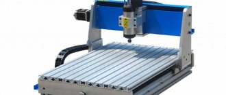
What can a CNC turning and milling machine do?
We are not talking about hobby-class lathes, on which a milling device is mounted and which are used in repair shops.
CNC turning and milling machines are a relatively new class of industrial machines that have higher productivity and advanced capabilities than classic CNC lathes.
The turning-milling machine can do everything that a conventional 2-axis CNC lathe can do + has an additional rotary C-axis and a turret with a driven tool, which allow off-axis processing (drilling, milling, tapping, etc. .).
For example, a part such as a flange is usually processed on two machines: a lathe and a drilling (or milling) machine. The turning and milling machine will produce a flange in one installation in a minimum of time.
Main advantages
Compared to manual machines, those equipped with CNC are four times more productive. Although the performance range varies from the specified settings and can be from one and a half to five times.
Due to the fact that a CNC machine combines the flexibility of universal equipment and the high productivity of an automatic machine, the problem of using such technology in both serial and individual production is solved.
Important!
Thanks to the latest electronics and the best computer technology, mechanical engineering, namely the production of parts for automobiles, is reaching a predominantly new level.
Due to the fact that the process is becoming almost completely automated, the need for qualified workers to operate the machines is falling. However, this cannot lead to unemployment, since craftsmen are now required who will monitor the serviceability of the CNC machine. Thanks to this, the quality of work improves without consequences.
The time required for fitting work is significantly saved due to the fact that the parts are made, one might say, according to one template, so they are interchangeable.
Due to the fact that all programs for the production of new products are recorded in the computer, there is no need to retrain personnel before switching to working with new products. You just need to turn on the desired program.
Parts that are made on a CNC machine are produced much faster. In addition, due to the absence of a person, the level of defects and unfinished work is significantly reduced.
How does a programmable C axis work?
The C axis - in CNC lathes - is a software control of the spindle rotation angle and holding it. Used synchronously with driven tools. The main parameter is the minimum spindle rotation angle (usually the minimum controlled rotation angle is 0.001°).
The C-axis provides precision bidirectional spindle motion that is fully interpolated with X- and/or Z-axis motion. Spindle speed can be commanded from 0.01 to 60 rpm.
Machines with a C axis, accordingly, must have a 3-coordinate CNC system with the possibility of linear and circular interpolation.
The C-axis can be driven by a spindle motor or a separate servo motor. An angular position sensor is mounted on the spindle body.
The operation of the C-axis depends on the mass, diameter and length of the workpiece and/or clamping equipment (chuck).
In machines with a C axis, the spindle operates in 2 modes:
- Main movement mode (turning) - the spindle is driven by the main drive and rotates at a given speed in accordance with the turning mode. The rotation speed is set by the CNC.
- C-axis mode - the spindle, at the CNC command, rotates to a given angle and is fixed (the C-axis is indexed).
C axis control
Basic spindle and C-axis control commands:
- M03 commands the spindle to rotate in the forward direction
- M04 commands the spindle to rotate in the reverse direction
- M05 commands the spindle to stop
- M154 includes C axis
- M155 disables C axis
The lathe automatically turns off the spindle brake if a C-axis motion command is given, and then turns it on again if the M codes are still active.
It is possible to move the C axis relative by using the H address code, as shown in the example:
- G0 C90. (C-Axis moves to 90. deg.) ;
- H-10. (C-Axis moves to 80. deg. from the previous 90 deg position) ;
Typical C-axis control program
Commands in Cartesian coordinates are converted into linear axis movements (turret movements) and spindle movements (rotation of the part).
Interpolation to Cartesian coordinates, example 1.
- (1) Designated cutting path;
- (A) Feeding a 1″ end mill into the workpiece from one side;
- (B) The C axis is rotated 180 degrees to complete the arc contour;
- (C) Feeding a 1″ end mill out of the workpiece.
Example of Cartesian interpolation
- o51121 (CARTESIAN INTERPOLATION EX 1) ;
- (G54 X0 Y0 is at the center of rotation) ;
- (Z0 is on face of the part) ;
- (T1 is an end mill) ;
- (BEGIN PREPARATION BLOCKS) ;
- T101 (Select tool and offset 1) ;
- G00 G18 G20 G40 G80 G99 (Safe startup) ;
- G98 (Feed per min) ;
- M154 (Engage C Axis) ;
- G00 G54 X2. C90 Z0.1 (Rapid to 1st position) ;
- P1500 M133 (Live tool CW at 1500 RPM) ;
- M08 (Coolant on) ;
- (BEGIN CUTTING BLOCKS) ;
- G01 Z-0.1 F6.0 (Feed to Z depth) ;
- X1.0 (Feed to Position 2) ;
- C180. F10.0 (Rotate to cut arc) ;
- X2.0 (Feed back to Position 1) ;
- (BEGIN COMPLETION BLOCKS) ;
- G00 Z0.5 M09 (Rapid retract, coolant off) ;
- M155 (Disengage C axis) ;
- M135 (Live tool off) ;
- G18 (Return to XZ plane) ;
- G53 X0 Y0 (X & Y home) ;
- G53 Z0 (Z home) ;
- M30 (End program) ;
Cartesian interpolation example 2
Cartesian interpolation example 2
- o51122 (CARTESIAN INTERPOLATION EX 2);
- (G54 X0 Y0 is at the center of rotation) ;
- (Z0 is on face of the part) ;
- (T1 is a drill) ;
- (BEGIN PREPARATION BLOCKS) ;
- T101 (Select tool and offset 1) ;
- G00 G18 G20 G40 G80 G99 (Safe startup) ;
- G19 (Call YZ plane) ;
- G98 (Feed per min) ;
- M154 (Engage C-Axis) ;
- G00 G54 X3.25 C0. Y0. Z0.25 ;
- (Rapid to 1st position) ;
- P1500 M133 (Live tool CW at 1500 RPM) ;
- M08 (Coolant on) ;
- G00 Z-0.75 (Rapid to Z depth) ;
- (BEGIN CUTTING BLOCKS) ;
- G75 X1.5 I0.25 F6. (Begin G75 on 1st hole) ;
- G00 C180. (Rotate C axis to new position) ;
- G75 X1.5 I0.25 F6. (Begin G75 on 2nd hole) ;
- G00 C270. (Rotate C axis to new position) ;
- G75 X1.5 I0.25 F6. (Begin G75 on 3rd hole) ;
- (BEGIN COMPLETION BLOCKS) ;
- G00 Z0.25 M09 (Rapid retract, coolant off) ;
- M155 (Disengage C axis) ;
- M135 (Live tool off) ;
- G18 (Return to XZ plane) ;
- G53 X0 (X home) ;
- G53 Z0 (Z home) ;
- M30 (End program) ;
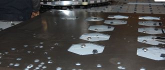
What metal operations can be performed
Thanks to the fact that the human factor has been reduced to a minimum, metal operations have become much easier and result in less waste. It turns out this way because of the program that is embedded in the computer.
It is a kind of template by which the computer understands whether the part is ready or not. This section will talk about the operations that a CNC machine can perform on metal.
External and internal turning of parts
Everything is simple here, at least for the car. The installed workpiece, which in the future will become a part, is fixed on the machine. It can be secured manually or, if the appropriate equipment is installed automatically (most often the automatic option is used).
Afterwards, external turning of the part begins using either a laser or a blade that is installed on the machine. Gradually cutting off the excess, the workpiece takes the shape of the desired part. This is how external turning of parts is done on a CNC machine.
With the internal everything is about the same, only with changes. After installing the workpiece, the machine begins to drill, or as it is called differently, drill a hole at the base of the workpiece.
Once the hole is ready, the computer will compare it with the template that is written in the given program. If there are any flaws, he will analyze whether it can be corrected (as a rule, yes, because machines rarely make mistakes). Afterwards the workpiece is polished and the part is ready.
Longitudinal processing of the workpiece
Longitudinal processing is a method that is used for the manufacture of strips, strips, tapes. Depending on the program that is installed on the computer.
Such work on a CNC machine is carried out mainly using a laser, as this allows you to get rid of defects and speeds up the work process. After installing the workpiece, the numerical control on the machine will process it in accordance with the specified algorithm of actions. The laser portal is driven by stepper motors on which it is mounted.
Roughing and finishing
To begin with, what is this anyway? Roughing of metal consists of adjusting the part to the desired size by removing layers of metal.
Typically, in a CNC machine, this role is performed by the computer after the part has already been cut. Finishing comes next and consists of polishing the surface of the product. The machine performs all this according to given algorithms.
Adjusting the length of parts
The program that is given to the computer clearly states the dimensions of the part. The blanks are also given in suitable sizes. Before inserting a part, the machine adjusts and sets itself up for production.
After that, he begins to do the work, after which he compares the size with those given by the person. If there are no deviations, the part is ready. If there is, the CNC machine begins to grind the part, removing layers of metal and adjusting the length.
Making grooves, recesses and holes
Grooves and recesses are holes that are made into a part. Such holes can serve either to allow another part to fit into them, or for installation to some device. A CNC machine makes such holes using a laser, making high-precision cuts.
They can be rectangular, T-shaped, dovetail, shaped, through, open, closed and others. What shape the hole will be depends on the part and the program that the person has installed in the numerical control.
Inch and metric thread cutting
Almost everyone has seen this type of carving. It is used mainly so that one part can be screwed to another. The main parameters in the manufacture of such threads are pitch and size. In this case, a step means:
- outer diameter, measured between the top points of the threaded ridges located on opposite sides of the pipe;
- internal diameter as a value characterizing the distance from one lowest point of the cavity between the threaded ridges to another, also located on opposite sides of the pipe.
All parameters need to be entered into the machine’s computer, after which it will cut out an excellent and even thread using a laser.
Reference! In any case, the parameters for making threads on a product are entered by a person into the computer of the machine, and the latter, acting according to an algorithm, uses a laser to make an excellent thread.
How does a driven tool work?
The driven tool allows you to significantly expand the capabilities of the machine, making the CNC lathe a machining center. The driven tool always works with the C axis.
The drive tool mechanism consists of the following components:
- A turret with a drive electric motor installed inside, which transmits rotation to the drive unit through a coupling;
- Drive units with tools (drills, taps, cutters), which are installed in the tool disk of the turret head. The drive unit has a specialized shank that acts as a coupling to transmit torque from the electric motor to the tool.
Technological operations performed by the driven tool:
- Milling of planes, flats, grooves, depressions, etc.
- Drilling coaxial holes of different diameters, both along the axis of the part and with an offset
- Machining surfaces and holes at an angle to the axis of the part
- Thread cutting using milling method.
Today in the world there are two most common tool holding systems for turning centers with driven tools.
These are VDI and BMT® systems. The BMT® system (Built-in Motor Turret - with a tool drive built into the turret) has the advantage of rigidly attaching the block to the turret head due to fastening with 4 bolts.
In addition, the BMT® system provides the ability to expand the number of tools due to intermediate positions of the turret (up to 24).
Approximate characteristics of the driven tool:
- rotation speed 4000..6000 rpm
- Power 4 kW
- Maximum torque 40 Nm
- Tool position change time 0.15 s
BMT turret
Drive tool control
Power-on commands
- M133 - turns on the spindle rotation in the forward direction
- M134 - turns the spindle in the opposite direction
- M135 - stops the spindle of the driven tool.
The spindle speed is controlled by address code P. For example, P1200 sets the spindle speed to 1200 rpm.
- M138 - spindle speed change on
- M139 - spindle speed change off
Spindle Speed Variation (SSV) allows you to specify a range over which the spindle speed continuously changes. This is useful for suppressing tool vibration, which can cause unwanted deterioration of the workpiece and/or damage to the cutting tool.
The control changes the spindle speed according to settings 165 and 166. For example, to change the spindle speed +/-100 rpm from its current speed on a command with a duty cycle of 1 second, set setting 165 to 100 and setting 166 to by 1.
This change will depend on the material, tooling and performance in your particular application, but 100 rpm for 1 second is a good start.
You can override settings 165 and 166 using address codes P and E when used in conjunction with the M138. Where P is the change in SSV (rpm), E is the SSV cycle (sec). See example below:
- M138 P500 E1.5 (Turn SSV On, vary the speed by 500 RPM, cycle every 1.5 seconds);
- M138 P500(Turn SSV on, vary the speed by 500, cycle based on setting 166);
- M138 E1.5 (Turn SSV on, vary the speed by setting 165, cycle every 1.5 seconds);
M138 is independent of spindle commands; After executing this command, it remains active even when the spindle is not running. In addition, M138 remains active until it is canceled by M139 or M30, or by the Reset or Emergency Stop command.
Turning and milling machines may have the letter “M” (Milling) in their names. This means that such a machine has the function of a driven tool.
How the Y axis works
The Y axis is an additional axis on lathes. Installing the Y axis allows you to expand the capabilities of your CNC lathe. The Y axis adds the function of machining the workpiece, outside the workpiece rotation axis or outside the perpendicular to the workpiece rotation axis. In other words, the presence of the Y axis allows for linear milling and off-axis drilling.
The Y-axis drive lifts the turret head above the spindle axis. The Y axis moves tools perpendicular to the spindle centerline. This movement is achieved by complex movement of the ball screws of the X and Y axes. Movement along the Y axis is realized through the simultaneous movement of the turret along the X axis and an additional axis with sliding guides. Today, this is the most advanced, reliable and stable solution.
A typical application for the Y-axis is making security holes on nuts.
Y axis
Y axis control
The Y axis can be controlled by commands and behaves similarly to the standard X and Z axes. There is no special command to enable the Y axis.
After a tool change, the lathe automatically returns the Y axis to the spindle centerline. Make sure the turret is positioned correctly before commanding rotation.
Standard G and M codes are available when programming using the Y axis.
When performing live tool operations, cutter type tool compensation can be applied in both the G17 and G19 planes. Cutter compensation rules must be followed to avoid unpredictable movement when applying and canceling compensation. The radius value of the tool being used must be entered into the RADIUS column on the geometry page for the corresponding tool. The tool tip is set to "0" and no value needs to be entered.
The following canned cycles can be used with the Y axis.
Axial cycles only:
- Drilling: G74, G81, G82, G83,
- Boring: G85, G89,
- Threading: G95, G186,
Radial cycles only:
- Drilling: G75 (grooving cycle), G241, G242, G243,
- Boring: G245, G246, G247, G248
- Threading: G195, G196
Example milling program with Y axis
- (1) Submission;
- (2) Accelerated movement;
Example milling program with Y axis
- o51121 (CARTESIAN INTERPOLATION EX 1) ;
- o50004 (Y AXIS MILLING) ;
- (G54 X0 Y0 is at the center of rotation) ;
- (Z0 is on face of the part) ;
- (T1 is an end mill) ;
- (BEGIN PREPARATION BLOCKS) ;
- T101 (Select tool and offset 1) ;
- G00 G18 G20 G40 G80 G99 (Safe startup) ;
- G19 (Call YZ plane) ;
- G98 (Feed per min) ;
- M154 (Engage C-Axis) ;
- G00 G54 X4. C90. Y0. Z0.1 ;
- (Rapid to clear position) ;
- M14 (Spindle brake on) ;
- P1500 M133 (Live tool CW at 1500 RPM) ;
- M08 (Coolant on) ;
- (BEGIN CUTTING BLOCKS) ;
- G00 X3.25 Y-1.75 Z0. (Rapid move) ;
- G00 X2.25 (Rapid approach) ;
- G01 Y1.75 F22. (Linear feed) ;
- G00 X3.25 (Rapid retract) ;
- G00 Y-1.75 Z-0.375 (Rapid move) ;
- G00 X2.25 (Rapid approach) ;
- G01 Y1.75 F22. (Linear feed) ;
- G00 X3.25 (Rapid retract) ;
- G00 Y-1.75 Z-0.75 (Rapid move) ;
- G00 X2.25 (Rapid approach) ;
- G01 Y1.75 F22. (Linear feed) ;
- (BEGIN COMPLETION BLOCKS) ;
- G00 X3.25 M09 (Rapid retract, Coolant off) ;
- M15 (Spindle brake off) ;
- M155 (Disengage C axis) ;
- M135 (Live tool off) ;
- G18 (Return to XZ plane) ;
- G53 X0 Y0 (X & Y Home) ;
- G53 Z0 (Z Home) ;
- M30 (End program) ;
Turning and milling machines may have the letter “Y” in their names. This means that such a machine is equipped with a Y-axis, which automatically means that this machine also has a driven tool (“M”).
Manufacturers and characteristics of popular models
Today, the global industry produces hundreds of lines of machine tools, each of which has up to a dozen models. A significant share is made up of Russian-made machines (Russia ranks 22nd in the world market). The country is currently unable to fully meet the needs of its own industry. Therefore, milling machines from a variety of companies are available on the domestic market, in particular:
1. DeKart turning and milling machines. Known as a manufacturer of wood processing equipment. He also produces one of the most budget-friendly brands for metal. The line includes woodworking machines with a base from 1200 to 2200 mm. Including:
- DeKart 1200Р (1500; 1800), with a spindle power of 3.5 kW and a workpiece diameter of 100-250 mm;
- DeKart 2000Р (2200), the difference in power is 4.5 kW and processing of parts up to 350 mm in diameter.
The movement of working elements is carried out simultaneously along three axes.
As for the software and the control itself, the manufacturer positions it as intuitive and easy to master within just a couple of days. To a certain extent, this is true, but only in relation to a qualified operator who already has experience working on equipment of this type.
2. The TX 75/75 line is the 120/120 brainchild of the Chinese company XKNC. It is characterized by its small size and high precision processing of parts at an affordable price. Even a private owner can afford to buy equipment, especially used equipment. Includes five machines created on a common base platform with a processing length from 75 to 120 mm with a maximum working field width of 250 mm.
The machines are designed for the production of small metal parts with precision accuracy. Up to 10 instruments can be installed in the turret. It is characterized by a short time for changing equipment (up to half a second). The disadvantage is the lack of controlled movement along the Y axis.
3. The B8D machine from the Chinese company JSTOMI is designed for a processing length of up to 200 mm with a workpiece diameter above the support of 230 mm. The maximum spindle speed is 4500 rpm. Motor 4.5 kW. Head with 12 elements. The machine is assembled from parts made in Japan (chuck, servos, bearings) and Taiwan (CNC system, guides), has 4 radial and 4 axial feed units.
4. TRAUB TNX65/42. It is also a relatively small unit made in Europe. Unlike analogues, its chain tool magazine is designed for 80 and 120 types of equipment. The machine has a counter spindle, four milling heads and the same number of supports. An unusual solution was a modular system that allows you to flexibly select machine parameters to suit the needs of a specific enterprise. The price of the equipment is also noticeably higher.
5. One of the most advanced lines today is CTX (alpha, beta and gamma) from German mechanical engineers. Includes three models belonging to the fifth generation. The machines are distinguished by the size of the processed field (maximum dimensions of the part):
- The alpha model can process parts up to 300 mm, has a main lathe chuck of 165 mm;
- Beta allows you to install an 800 mm part with a 300 mm chuck;
- The range takes parts up to 2000 mm, has a chuck of 500 mm and a maximum turning diameter of 600 mm.
Depending on the processing diameter, the torque of the machines also varies.
Each model has a control panel equipped with a 19″ diagonal touch screen, where almost all parameters of the processing process are displayed.
The machine heads house up to 36 different tools. The CNC controls the work on the X axes; Y; Z both main and additional. Manufacturers position active water cooling of all components, the heating of which during operation increases by more than 15°C, as an important feature of the mechanism. Integrated spindle motors are used as drives.
6. Line of CTX 800 TC machines from the same company. Their peculiarity is the presence of an unusual chain head for processing tools, which can accommodate up to 80 different types of equipment. With traditional ergonomics and design, the machine is distinguished by its high processing speed: up to 20 thousand rpm. It is possible to purchase machines only with prior approval of the configuration. Production is located in the Ulyanovsk region of Russia.
7. FS65MF3 is a modern high-precision machine made in Russia. Equipped with a manipulator magazine for 16 tools. The 20 kW drive provides spindle speeds of up to 12,000 rpm. The movement of controlled drives is carried out along three axes, with dimensions of the working platform 650/380/450. CNC developed by SIEMENS. Equipped with a plate conveyor and a chip removal tank. For a device with similar characteristics, it has a relatively low weight (3.4 tons).
Tips for choosing turning equipment
CNC turning and milling machines, even used ones, cost at least a quarter of a million. Obviously, before you buy such expensive equipment, you need to clearly understand the problems it solves.
- First of all, these are the dimensions of the largest part to be processed. Determine its dimensions and add a margin of 3-5 cm for each. The resulting value will be the parameters of the processing field for the future acquisition.
- How complex parts are expected to be manufactured? The characteristics of the CNC, the number of controlled movements, and the need for drive units depend on this.
- A set of metalworking elements in a store.
- Data on the types of tools for processing the part are in the technological map for its manufacture.
- The presence of a Y axis for a machine, although it increases the cost, expands the list of operations by an order of magnitude.
- Finally, a parameter that, oddly enough, is often forgotten: the dimensions of the machine, its weight, as well as the conditions for its normal operation. Don’t forget to compare them for the selected option with the capabilities of your workshop.
When purchasing used equipment, an even more scrupulous approach is required. A preliminary check of the operation of all mechanisms goes without saying. In addition, immediately decide on a company that provides CNC.
In Russia, programmable machines using punched cards have been produced since 1960. Today you can buy used mechanisms manufactured during the Soviet era, with controls rebuilt to modern standards. Such equipment is reliable, but may have functional limitations caused by inconsistencies in the CNC, so before purchasing it, all desired use cases are carefully tested. Purchasing a machine does not mean getting the opportunity to do metalworking. It is possible that in addition to the tools included in the kit, you will need to buy additional equipment, which should be thought about in advance.
Prices
| Name | CNC | Y axis | Machining field, mm (turning length/workpiece diameter above the support) | Price, rubles | Production | Note |
| XKNC TX75D | FANUC 0i-TD | No | 210/95 | 440 000 | ||
| NXX-26A | SYNTEC | Yes | 170/350 | 574 000 | China | |
| VISPROM FPV-30G | VISPROM FPV-30G | Yes | 290/300 | 680 000 | brand Russia | |
| JSTOMI | FANUC | Yes | 350/150 | 200 000 | Japan, Taiwan | assembly China |
| FS65MF3 | Siemens SINUMERIC | Yes | 450/650 | 3 570 000 | Russia | |
| FS85MF3 | Yes | 550/850/ | 4 095 000 | |||
| SOLEX HM503H | FANUC | Yes | 650/850 | 6 038 135 | Japan | assembly China |
| 6VR13F3 | Mach3 | No | 880/650 | 950000 | Russia | boo |
Less than 50 years have passed since the appearance of the first CNC machines. Drums with protruding pegs gave way to punched cards, which in turn gave way to processors. If previously one turner was needed for each machine, now an engineer services a line of dozens of units. Today we are talking seriously about 3D printers, which will supposedly soon replace turning and milling machines. But I think this is still a long way off. However, metalworking is completely different. Most likely, the devices will occupy their niche, if at all displacing traditional methods of manufacturing parts, then not by much.
How does the counter spindle work?
Installing a counter-spindle (counter-spindle) S2 with a full C axis allows you to process the part from the reverse side (drilling, milling, perforation) without additionally moving the part into the machine, therefore saving the time required to completely process the part. This capability allows the processing of parts of increased complexity and precision.
A typical application of a counter spindle is the manufacture of shafts and end machining on both sides.
The spindle and counter spindle of the turning machining center are synchronized to ensure high precision workpiece positioning, which improves the precision of heavy machining.
Turning and milling machines with a sub-spindle may have the letter “S” in their name.
CNC lathe with Y axis and counter spindle
How to write a control program
Programs for operating CNC machines are made in three steps, each of which determines what the new part will look like:
- Creation of a three-dimensional model. This stage is the creation of a model of the workpiece with which the work will be carried out. This is mainly done not by operators, but by designers, since not everyone understands so well how to make a good three-dimensional model.
- Instructions. Having a three-dimensional model, the operator sets the parameters that the machine will have to perform when working with the workpiece in order to get the part.
- Test run. It is necessary to check whether the program was written correctly to work. After all, if you run a bad program on a machine right away, without a test, it will ruin all the workpieces. Therefore, the operator looks to see whether the machine is performing the job correctly with the given program, and then looks at the result and decides whether modification is required or not. Most often it is, of course, required, but it cannot display any critical errors.
Once the program has been installed, the machine is ready for use. There are five special applications for writing such programs:
- AutoCAD.
- T-FlexCAD.
- NanoCAD.
- ArtCam.
- SolidWorks.
Now we will talk about each one separately.
AutoCAD
This program was developed by Autodesk specifically for automatic design of turning operations. AutoCAD has 3D modeling functions, as well as the ability to work with 3D scan data, which allows you to save money on designers. But, due to the lack of three-dimensional parameterization, this program is not the best choice.
T-FlexCAD
This program was developed to develop different types of work with lathes. It has all the necessary functions, but it is not the best choice and is not popular.
NanoCAD
This program can work with both three-dimensional and two-dimensional models. With its help, work calculations can be carried out, 3D and 2D models, various drawings and much more can be prepared. Thanks to this program, the work of operators is greatly facilitated.
ArtCam
This program is needed exclusively for creating a three-dimensional model. Calculations of work or anything similar cannot be done on it, but the models are of very high quality.
SolidWorks
This is not just a program, but a whole software complex. It was released back in 1995, but is still considered one of the best among the development of programs for lathes using a CNC system. True, this software package costs a decent amount, but it perfectly demonstrates the principle “price equals quality.”
Multi-purpose turning and milling machines
C-axis lathes with driven tools are significantly superior to classic CNC lathes in terms of capabilities and performance, but they also have their drawbacks: one of which is a small number of tools in the turret (maximum 24).
The shortcomings are completely compensated for by the use of a separate rotary turning and milling spindle with a tool magazine.
After installing the milling spindle, the lathe can be called a multi-purpose lathe. Multi-purpose machines combine the functions of a CNC lathe and a machining center and implement the Done-In-One concept (done in one setup).
INTEGREX e-500H II multi-purpose turning and milling machine
Multi-purpose turning and milling machine INTEGREX e-500H II
The multi-purpose turning and milling machine INTEGREX e-500H II has the ability to use all types of operations in one setup - turning and boring operations, milling, drilling, intercepting parts from the main to the second spindle and much more. Ideal for high precision machining of large shaft type parts for most industries.
The machine is equipped with a powerful, high-torque integrated motor-spindle with two speed levels to improve processing capabilities under heavy cutting conditions.
The C axis (with a rotation resolution of 0.0001°) is activated using a plug-in worm gear characterized by high positioning accuracy.
Single spindle milling head (50 taper) with automatic tool changer ensures easy tool installation with minimal risk of collision.
Thanks to the B-axis contouring mode, the milling spindle can perform various types of operations in one workpiece setup.
The automatic CNC-controlled steady rest and rear center ensure safe machining of long parts.
Main parameters of the multi-purpose turning and milling machine INTEGREX e-500H II
- The 37 kW milling head has a stroke in three axes (X - 870 mm, Y - 500 mm, Z - 1598 mm) and rotation along the B axis (240° (-30° +210°), indexing 0.0001°).
- 40 HP spindle The C axis (with a rotation resolution of 0.0001°) is activated using a plug-in worm gear.
- CNC-controlled automatic steady rest (optional)
- 5-axis machining
- Automatic tool changer with 80 or 120 positions (optional)
- Long boring bar system (max. length 1,000 mm) for 2 tools (optional)
What it is?
For processing parts with a complex configuration, making grooves and grooves, processing on one type of equipment is not enough. The part has to be removed and placed on another machine. In this case, it is necessary to set it with high accuracy relative to the base and the already processed finishing dimensions.
To mill all surfaces, drilling and boring the side planes, milling heads are used. They significantly increase the technological capabilities of the machine, turning it into a universal, multifunctional unit. Using a milling head for a machine tool, they change the position of the tool relative to the spindle axis, allow you to do plane processing on turning equipment, and work without stopping with different tools.
Important!
They have a complex mechanism inside that automatically changes the position of the cutting tool. They work in harmony with the equipment, according to one program.
Symbols, terms and explanations
Symbols for the configuration of turning machining centers:
- M - (Milling) driven tool;
- Y - controlled Y axis;
- S — (Spindle) counter spindle;
- T - (Tailstock) tailstock.
Explanation of terms
The spindle motor is an integrated spindle drive (ISM). The machine spindle is the axis of the drive motor. The CTX series (DMG) uses 9 standard sizes of motor spindles. The motor spindles have high precision and thermal stability due to liquid cooling. Motor spindles are used both in the main drive and in the counter spindle. (The CTX beta 800 machine is equipped with an ISM 76 - power (100% ED) 25 kW, torque (100% ED) 280 Nm. Rotation speed up to 5000 rpm, built-in C-axis (0.001°).
C-axis - in CNC lathes - software control of the spindle rotation angle and holding it. Used synchronously with the driven tool. The main parameter is the minimum spindle rotation angle (In the CTX series, the minimum controlled rotation angle is 0.001°). Can be built into the spindle motor or have a separate servo motor.
Y-Axis - The Y-axis expands the capabilities of live tools. Y-axis mechanisms allow you to guide the tool offset to the axis of rotation of the part. The main parameter is the maximum stroke
Counter spindle - in CNC lathes - an additional spindle (counter spindle) installed in place of the tailstock. If it is necessary to process a part from the opposite side, it is transferred from the main spindle to the counter spindle. To do this, upon command from the CNC, the rotation speed of the counter spindle is synchronized with the speed of the main spindle, the counter spindle moves, grabs and clamps the workpiece. Processing continues on the other side of the part.
Linear guides are rolling guides. To move the turret head along the X and Z axes, CTX series lathes use ball screws and ball (roller) linear guides, which have a low coefficient of friction (low heat generation), no “sticking” effect (high speed up to 30 m/min), Consistent precision (low wear) and very low lubrication requirements.
Linear drive – highly dynamic drive for maximum dynamics and long-term precision in the X-axis (upper turret). The drive with high speed strokes of up to 60 m/min and accelerations of up to 1.5 g reduces the auxiliary time to a minimum. The linear drive consists of linear guides and a linear motor, the ball screw assembly is excluded and the friction force approaches 0.
Direct Drive is a technology for driving a driven tool directly from an electric motor.
TRIFIX® is a three-point mounting method for mounting a tool onto a VDI turret with greater precision than conventional mounting.
A driven tool is a rotating tool (drill, cutter, tap) designed for installation in a turret.
VDI - (Verein Deutscher Ingenieure - Association of German Engineers) turret head with tool holders for CNC lathes (Tool holder fastening: a wedge with teeth on the shank of the holder), made according to the German standard DIN 69880 (VDI 3425) (GOST 24900-81). VDI connections are available in six sizes 16, 20, 25, 30, 40, 50 depending on machine power and tool size. Used for fastening both driven and non-driven tools.
BMT® - (Built-in Motor Turret) turret with built-in tool drive.
BOT - (Bolt-On Tools) turret with bolt-on non-drive tools. Haas documentation term.
TWIN is a machine with two independent working areas - two turret heads that work simultaneously with spindles. Patented concept from DMG.
CNC Machine Selection Guide
If you are just starting a business and have no experience in this field, choosing a CNC milling machine can confuse you - there is so much variety in the industrial tool market.
Only many years of experience and specific knowledge allow specialists to select CNC machines in accordance with the requirements for the equipment. Many people simply get lost in this abundance, and this is not surprising - choosing the best CNC machine can be difficult even for professionals if they do not follow the latest products in the tool market, the range of which is constantly expanding and improving.
By what criteria is it better to choose a CNC machine?
It depends on what it will be used for. From the materials, the profile of the work, the required speed and accuracy, and the required resource. Many significant characteristics of such machines directly depend on their equipment - on the properties of their components and consumables, on design features. Let's look at the most basic ones.
Spindle
The spindle is one of the main parts of a milling machine. It depends on the spindle which cutters can be used with this particular machine, at what angles they can be fixed and how exactly to use them. The spindle drive is usually built-in - that is, the spindle is a powerful compact electric motor with a collet for clamping the cutter.
Much directly depends on the quality of the spindle - a good spindle will last a long time, constantly pleasing you with the quality of work, but a bad one can ruin not only the product, but also damage the machine itself in the event of an accident, or even injure personnel. The choice of spindle should be approached responsibly, always carefully listening to the recommendations of the machine manufacturer and paying attention, first of all, to the products of well-known and reputable component manufacturers.
Milling area
This is one of the most important characteristics of a CNC machine - the size of the milling area determines what size product the machine can process. Each narrow area of application has its own size requirements; more universal machines have an adjustable milling area, or obviously exceed the requirements for most common application cases.
The design of the platform is also important - it should not cause difficulties in securing and clearly positioning the workpiece part, otherwise serious defects are possible. When choosing a CNC milling machine for work, you need to decide in advance on the dimensions of the parts to be processed so as not to get into trouble.
Purpose of the machine
CNC machines are divided primarily according to the material they are designed to process, as well as by area of application.
Metalworking equipment
Metalworking CNC machines differ from others primarily in the strength and power of their design, which allows them to work with both metal and most other materials.
To reduce wear and avoid jamming of the cutter, they are often equipped with a supply of coolant to the cutter, usually water or oil, directly into the working contact area, and many of them are equipped with a powerful air suction - a design designed to mount the socket of an industrial vacuum cleaner, to automatically remove chips from the processed material. surfaces.
Woodworking equipment
CNC machines for working with wood, as well as composites and plastics, differ little structurally from machines for working with metal, but have a slightly simpler design and lower requirements for power and strength characteristics, which is naturally due to the specifics of the material.
The cutter is cooled by air, and more often it is completely absent, since its presence is not critical. Chip removal is also usually not provided for and is carried out manually by the operator. Accordingly, the cost of such machines is usually somewhat lower, their maintenance is simpler and cheaper, and their prevalence is greater.
Equipment for the manufacture of cabinet furniture
CNC machines designed for the production of cabinet furniture have their own characteristics - in particular, the dimensions of the milling area in them exceed those of other CNC milling machines, since the parts to be processed may have a larger area compared to other areas of CNC application.
Accordingly, a furniture CNC machine will have larger dimensions in all dimensions, as well as greater complexity and cost of the frame and guides than a similar machine for working with smaller objects. Otherwise, they differ little from machines for processing wood, plastic and composite materials.
Glass processing machines
Glass-processing CNC milling machines differ from machines for metal processing mainly in that they use special cutters with carbide, diamond and corundum working surfaces.
Milling cutters can be either specially coated or all-sintered - such components are created by baking diamond chips at high temperatures and high pressure, which gives an unusually strong and durable tool.
Also, in machines that process glass, the supply of working fluid to the area of contact of the cutter with the material is mandatory - this is due not only to the need to cool the cutter when working with such a hard material as glass, but also to the necessity of immediately eliminating waste fragments of material - so that they do not interfere with further work and do not spoil the part by getting back into the place of contact between the cutter and the workpiece, on the one hand, and so that they do not get into the air that the machine operator breathes. In addition to glass, such machines can process polycarbonate, plexiglass of various compositions and other solid materials, as well as metal workpieces.
You can choose a CNC machine for working on glass based on its compliance with these mandatory criteria.
Stone processing equipment
CNC milling machines for working on stone are designed for engraving and making complex volumetric bas-reliefs on hard materials such as natural stone of various types - granite, marble, sandstone, as well as on artificial stone slabs made of granite chips with polymer.
The specifics of working with stone simultaneously require large processing areas, high hardness of the material, and increased weight of the workpieces. Also, the stone is characterized by the fact that when working with it there is a need for both constant circulation of water in the work area and the removal of crumbs and dust with a vacuum cleaner - water itself does not save from dust of the coarse fraction, characteristic of mineral materials.
Such machines can easily cope with other materials - from wood and PVC, to, often, even glass and metal, and therefore will be useful not only for manufacturers of stone products, but also for those whose professional interests are much broader.
This is, perhaps, the most advanced equipment for milling with program control, which can do almost everything in this area of production, however, it is overly powerful, bulky and expensive for most work not directly related to its purpose.
No matter how great the temptation may be to get a truly universal CNC milling machine, if your tasks do not include stone processing, consider purchasing something more specialized from the ones listed above.
These are perhaps the most basic points that you need to be aware of when choosing a CNC milling machine. And even if at first it seems that if you need to buy a CNC milling machine, the choice is not easy, it’s not so scary. Now we will focus on the features of CNC milling machines.
Types of kinematic models of the machine
When preparing to work on a CNC milling machine, kinematic models of the machine are used, which are a software simulation of this equipment and are necessary for the correct preparation and predictability of the machine’s actions during program execution.
The kinematic model of the machine necessarily contains information about the working area, its dimensions and location relative to the stationary base of the machine, the location and possible trajectories of the working head - the cutter holder, and other physical parameters of the equipment - distances, dimensions - all that have a direct impact attitude towards the work performed by the machine.
Examples of machines and their models:
Preparing a control program
To work on CNC milling machines, CAD/CAM systems are used - software packages designed to translate data from drawings and models into a form of commands understandable to the machine.
These are DeskProto, VCarve Pro, ConstruCAM-3D, ArtCAM, NX CAM, SprutCAM and Mach3 software products.
The entered data on the size and shape of the part becomes control trajectories, which, in turn, turn into control programs in the postprocessing process.
Postprocessor
A postprocessor is a special software product that turns data on part parameters into an individual program that controls the movements of the tool and/or workpiece for each specific machine.
Here you can read more about the development of kinematic models, using the example of industrial systems from Siemens.
You can also find useful information in the technical literature library.
Detailed information on working with each specific machine can be obtained on the official website of its manufacturer. This is the most reliable option and will save you from many mistakes.
Control
In some cases, when you have to work on a serious industrial machine, you can set a program for processing some more or less simple part manually, through the machine control panel. In this case, you should strictly follow the manufacturer's instructions and follow all the necessary steps sequentially.
Control panel for one of the CNC milling machines:
When creating elements of more complex shapes, it is impossible to do without the use of a computer, and many compact machines are even controlled only through a connected PC.
Multi-axis machining
CNC milling machines are divided into vertical and horizontal - according to the location of the working head, respectively - top or side, and are also divided according to the number of processing axes - into three-axis, four- and five-axis.
Accordingly, the more coordinate axes of tool movement, the more efficiently and with greater complexity the part can be processed.
Cutters used
Depending on the specifics of the work - on the material, the required forms of processing and other factors, CNC milling machines use a large number of various cutters. The cutters are single-start, double-start, spherical, v-shaped, spherical cone, pyramidal radius with one or two cutting edges, engraving, cutting, etc.
Spherical and pyramidal cutters are used for deep removal of material from a part, processing corners, and creating recesses of the appropriate shape. Cutting and engraving cutters of various shapes are used for engraving, cutting parts, processing the edges of the product, and for shaping - creating a bas-relief image. Radius and fillet cutters, both convex and concave, are used for processing corners, edges of countertops and other parts, chamfering, etc. Face mills allow you to create holes, unlike drills, of any shape.
Examples of cutters used:
The variety of cutters varies from the simplest, similar to an ordinary drill or auger, to very complex ones, made of different materials and all kinds of shapes, with a different number of cutting edges. This provides a wide range of tasks they can solve.
For each material and type of work, an individual selection of cutters is required, which our specialist will help you choose.
CNC milling machines are an excellent tool that, when used correctly, can create a very wide range of products, from advertising structures to parts of other machines, from kitchen cutting boards to jet aircraft engine parts. The scope of their application is almost limitless, and the range and degree of availability are increasing every day.
Now not only a machine-building plant can afford such equipment, but also a relatively small workshop, which is good news.
Want more interesting news from the world of 3D technology?
Subscribe to us on social media. networks:
Russian manufacturers of turning and milling machines
JSC NIPTI "Mikron", Vladimir
Mikron NIPTI (Research Design and Technology Institute) was founded in 1957. Address: 600001, Russia, Vladimir, st. Dvoryanskaya, 27a bldg. 7, Website https://mikron33.ru/history.html
Currently, NIPTI Micron produces:
- TFC 1200-5 is a multi-purpose turning and milling center.
Southern Heavy Machine Tool Plant, LLC (YUZTS), Krasnodar
YuZTS Southern Heavy Machine Tool Plant, Krasnodar - was created in 2016 on the basis of the Krasnodar Machine Tool Plant named after Sedin (KZTS).
Currently, YuZTS produces:
- MF4M - Portal turning and milling center for processing large-sized parts of complex shape with various holes and grooves.
- VMM - Portal turning and milling center for processing large-sized parts of complex shapes with various holes and grooves.
- VC GANTRY MACHINE - Portal turning and milling center for processing large-sized parts of complex shapes with various holes and grooves.
- VCPR GANTRY MACHINE - Portal turning and milling center for processing large-sized parts of complex shapes with various holes and grooves.
Machine tool group STAN, Moscow
STAN - Machine Tool Group, Moscow - private company founded in 2012.
The companies of the Stan group produce turning and milling machines:
- STT 55F (1728F) – Turning and milling machining center
- STT 70F (1740F) – Turning and milling machining center
- STT 125F (1750F) – Turning and milling machining center
- STT 30 (1715) – Turning and milling machining center
- STT 55 (1728) – Turning and milling machining center
- STT 70 (1740) – Turning and milling machining center
Project "Machine Tool Building". FORT brand machines
FORT is a trademark of machine tools produced within the framework of the Machine Tool Building .
The project is being implemented by the partners of the “Machine Tool Building” project, which produce turning and milling machines:
- VNS – CNC lathe with horizontal bed
- VNS-1800 – CNC lathe with horizontal bed
- VNS-2200 – CNC lathe with horizontal bed
- VNS-2600 – CNC lathe with horizontal bed
- VNS-5000 – CNC lathe with horizontal bed
- VNS-6500 – CNC lathe with horizontal bed
- VNS-2800A – CNC lathe with horizontal bed
- VNS-3000 – CNC lathe with horizontal bed
- VNS-3500 – CNC lathe with horizontal bed
- VNS-4000 – CNC lathe with horizontal bed
- MT-52 – CNC lathe with inclined bed
- NT-500 – CNC lathe with inclined bed
- NT-700 – CNC lathe with inclined bed
- TS-35A – CNC lathe with inclined bed
- TS-35V – CNC lathe with inclined bed
- S-300TMU – CNC lathe with inclined bed
- T-42MSU - Lathe with counter spindle
- S-200TS — Lathe with counter spindle
- S-200TSM — Lathe with counter spindle
Ulyanovsk Machine Tool Plant, LLC (DMG MORI)
The world's largest Japanese-German machine tool concern DMG MORI has built an assembly plant in Ulyanovsk. The plant was launched (registered) on 06/04/2012
CNC lathes:
- CTX 310 ecoline – CNC lathe Ø 200 × 455 mm
- CTX 510 ecoline – CNC lathe Ø 465 × 1050 mm
- CTX alpha 500
– CNC lathe Ø 200 × 575 mm - CTX beta 800
– CNC lathe Ø 410 × 850 mm - CTX beta 800 TC
– turning and milling center Ø 500 × 750 mm - CTX gamma 2000
- CNC lathe Ø 700 × 2065 mm - CTX gamma 2000 TC
– CNC lathe Ø 700 × 2000 mm
Kovrov Electromechanical Plant Federal State Unitary Enterprise, KEMZ Kovrov
Kovrov Electromechanical Plant, KEMZ was founded in 1898 in the city of Trekhgorny, Vladimir region.
- KTS 3000 (Y, S) – Turning and milling machining center
- KTS 4000 (Y, S) – Turning and milling machining center
- KTS 5000 (Y, S) – Turning and milling machining center
- KTS 4000 TM - Turning and milling machining center with 2 turrets
- KTS TK 3108 – Turning and milling machining center with BMT tool blocks
- KTS TK 3110 – Turning and milling machining center with BMT tool blocks
StankoMashStroy, LLC Penza
Machine tool manufacturing company founded in 2006. Enterprise address: 440028, Penza, st. German Titova, 9A. Website: https://16k20.ru
The company produces universal screw-cutting lathes, CNC lathes and machining centers:
- ST25L — Turning machining center
- ST25LM – Turning machining center
Moscow Machine Tool Building
DMTG Moscow machine tool building was founded in 2022.
The company has established large-unit assembly of milling, drilling, and lathes. They make it possible to make parts for the automotive, aviation, military industries, as well as medical equipment. This is a new generation of technology in machine tool industry.
- CL - Turning center
- CL-15 – Turning center
- CL-20A – Turning center
- DL20M – Turning center
- DL25M – Turning center
- DL30M – Turning center
- DL32M – Turning center
- DL40M – Turning center
- DL-20MH – Turning center
- DL-25MH – Lathe center
- DL-30MH – Turning center
- DL-32MH – Turning center
- DL-40MH – Turning center
- CLD15 – Turning center
Machine tool plant Tulamash, LLC NPP
The Tulamash Machine Tool Plant was founded in 2013 and is a subsidiary of AK Tulamashzavod JSC, specializing in metalworking equipment. Website: https://cnc-tulamash.ru
NPP Machine Tool Plant Tulamash is engaged in the development and production of machine tools and critical machine components, including spindle units, guides of machine tools of the highest accuracy classes.
- 1TGK-4302 – CNC lathe
- 1TGK-4302 – CNC lathe
- 1TGK-4302+S – CNC lathe
- 1TGK-4302+Y – CNC lathe
- 6TVK-110 – Milling center
General information about the design
Example of a turning and milling installation
The main difference between turning and milling equipment and similar classic models is the presence of CNC. It is necessary to improve the quality of workpiece processing and minimize the influence of the “human factor” during work.
However, this entails an increase in the complexity of the equipment - electronic units are needed to coordinate the actions of various machine components. In addition, the presence of these units significantly increases the size of the equipment. This is due to the separation of functions (milling and turning), which can be performed by separate units of equipment.
Using turning and milling units with a CNC unit, it becomes possible to perform the following operations:
- turning of parts of various shapes. These include external and internal metal processing, thread formation, formation of ledges and irregularities of complex shape;
- milling work. Their type depends on the configuration of the cutting part of the tool. This can be the initial roughing of the surface or the finishing stage of forming the final shape of the part.
If the design of the machine provides only one movable working head, it must have a cone for installing a cutter or cutter. Most often these are HSK, Capto or BT models. The design depends on the mounting dimensions of the tool and the load parameters on the holder during a certain operation.
Turret-type lathes have similar properties. But due to the low speed of movement of the working tool, the list of their functions is limited compared to turning and milling centers controlled by CNC.
5-axis machine. Video.
- Lathe operator's manual. Next generation control system 96-RU8910. Revision M. February 2022. Haas Automation Inc.
Bibliography
Useful links on the topic
- Manufacturers of metal-cutting machines in the USSR and Russia
- Manufacturers of lathes in Russia
- Manufacturers of milling machines in Russia
- Manufacturers of grinding machines in Russia
- Manufacturers of turning centers
- Manufacturers of 5-axis centers in Russia
- Manufacturers of machining centers in Russia
- Manufacturers of drilling machines in Russia
- Manufacturers of forging and pressing equipment in Russia
- Directory of machine tool and KPO manufacturing plants
- Manufacturers of woodworking machines in Russia
- Manufacturers of household woodworking machines in Russia
- Manufacturers of chipping machines in Russia