Sawing is the processing of metal with a cutting tool - a file, with the help of which a layer of metal is removed from the surface of the part/workpiece. Thus, the parts are given the required dimensions, a given shape, the required accuracy and surface roughness. The following are subjected to filing in plumbing:
- external flat and curved surfaces
- external and internal, complex shaped surfaces
- recesses
- holes
- grooves
- projections
Filing is divided into preliminary (roughing) and final (finishing and finishing). Rough and fine filing is performed with different files. Files are made from tool and carbon steel. The length of a file is considered to be only the length of its cut part (working length). Files are made with lengths from 100 to 400 mm.
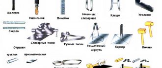
Filing tool - types
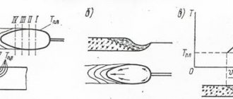
The size of the file cut is selected depending on the thickness of the layer being removed, the required surface cleanliness and processing accuracy. Rasp-cut files are used for processing wood, leather, rubber, rubber, bone, etc. Babbitt, lead, zinc and other metals are sawn with a rasp. Files with a single cut are used for processing soft metals (brass, zinc, babbitt, lead, etc.), as well as for processing wood. Double cut files are used for machining steel and cast iron. It is not recommended to file soft metals with “velvet” files, as their teeth quickly become clogged with shavings and stop cutting. The length of the file is selected depending on the size of the surface being processed. The larger it is, the larger the file should be. The length of the file must be at least 150 mm greater than the length of the surface to be filed.
Selecting the cross-sectional shape of the file
The cross-sectional shape of the file is selected depending on the type, size and location of the surface being processed in accordance with its purpose.
The cross-sectional shape of the file is selected according to the outline of the surface being processed (Table 2).
Table 2. File cross-sectional shape and its purpose
| Types of files | Purpose |
| Flat and flat sharp-nosed blades are designed for filing easily accessible flat and convex surfaces, sawing splines and grooves (size h and larger), sawing rectangular holes | |
| Square (tetrahedral) are designed for sawing square and rectangular holes (size b and larger), narrow flat surfaces that are inaccessible for work with a wide flat file | |
| Triangular and rhombic are designed for filing internal sharp corners, triangular holes and planes (sizes b, h and larger), in places inaccessible to a flat file | |
| Round and semicircular are intended for sawing round or oval holes, concave and flat surfaces (sizes d, b, h and larger), for filing with the flat side of planes, with the semicircular side of concave surfaces (semicircular recesses) | |
| Hacksaws are designed for filing internal corners, wedge-shaped grooves, narrow grooves, planes in triangular, square and rectangular holes (sizes b, h and larger) |
Filing techniques.
The greatest labor productivity during filing is ensured when the upper surface of the vise jaws is located at the level of the worker’s elbow. The position of the worker's legs and body during work has a significant impact on filing performance. The most comfortable position is one in which the mechanic's body is approximately 45 degrees with a line passing through the jaws of the vice. The movement of the file must be strictly horizontal, therefore the vertical forces on the handle and nose of the file must vary depending on the position of the point of contact of the file with the workpiece. During the working movement of the file, the force of the left hand must be gradually reduced. By adjusting the pressure on the file, one achieves a smooth filing surface without blockages at the edges. It is necessary to press the file against the workpiece only during the working stroke (from yourself). During the return stroke, the file should only slide along the surface. The rougher the processing, the greater the force during the working stroke. Filing the surface usually ends with its finishing. In metalworking, surfaces are finished with personal and velvet files, paper or linen abrasive skin, which is wrapped around the file, and abrasive stones. In this case, the direction of movement of the file can be transverse, longitudinal or circular strokes.
Plumbing; training manual / V.N. Feshchenko
Metal filing. Processing metal with a file.
What is metal filing?!
Filing is the process of manually processing a surface using files. A file is a tool with a large number of notches or cuts, forming very small teeth, which are used to remove chips during the translational movement of the file (Fig. 1).
Rice. 1. File:
1 – nose; 2 – edge (wide and narrow); 3 – rib; 4 – heel; 5 – tail; 6 – handle.
File names.
Files can be divided into regular files, needle files, rasps and machine files. Files are manufactured with single-row and double-row cuts. Based on the size of the notch pitch, files with a large pitch are called bastard files, with a medium pitch - personal files, and with a small pitch - velvet files.
File shapes.
The shapes of files are: flat, blunt-nosed and sharp-nosed with a smooth or notched edge, semicircular, square triangular and round (Fig. 2).
Rice. 2. File shapes:
a – flat; b – semicircular; c – square; g – triangular; d – round; e – needle file.
In boiler production, filing is used in rare cases:
- for small craft work;
- for particularly careful fitting of parts.
Since the filing operation is very expensive and ineffective.
Storing files.
Files should be stored in a tool box, laid out in one row, with spaces between them, protected from dirt, oil, water and especially sanding dust. After work, files must be cleaned with steel brushes to remove dirt and metal particles.
How to attach a handle to a file?!
The files have wooden handles with a metal ring on the neck. To avoid cracks, the handle attachment must be done carefully. The tail of the file is gradually inserted with a rotational movement into a small hole drilled in the end of the neck of the handle. The sharpened edges of the file tail drill out the hole. At the same time, tap the head of the handle on the workbench. After some deepening, the handle is removed and the file tail is cleared of wood shavings. Then the operation is repeated until the handle fits tightly to the lower edges of the file. Sometimes, instead of drilling, they use a thin steel rod heated red-hot to burn a hole in the handle.
Filing technique.
The success and accuracy of filing depends on the correct pressure on the file and maintaining the file while working in a position parallel to the surface being filed.
Filing occurs more quickly if the pace of movement is low and the pressure on the file is high. When filing wide surfaces, the work is easier and more correct, since the plane itself is a good guide.
Clean the file with a cord brush (Fig. 1.7.10, a
), one side (the bristles) is used to remove metal particles that are stuck in the grooves of the notches, and the other (bristle) is used to complete the cleaning. Move the brushes around the nozzle.
Rice. 1.7.10. File cleaning: a
- cord brush;
b
- scraper with soft metal
A metal rod with a flattened end is inserted into the handle of the brush (called a cleaning rod); It should serve to remove those particles that were lost after cleaning with a wood brush. If there are no brushes, then the teeth of the file should also be cleaned with special scrapers made of aluminum, brass or other soft metal (Fig. 1.7.10, b
). Hard steel or copper is used for which it is not necessary to cut the splinters, since the first one presses the notch, and the other exchanges the teeth.
After using a file, clean the soil with a piece of birch wood (along the rows of notches), and then with a brush. Heavily lubricated files will melt in extinguishers or gasoline.
Flash animation. Click on the field to start
Vibir drink.
For singing work, select the type of file, its type and the number of the notch.
The type of file is determined by the shape of the marked surface, and the length - by its dimensions. The final file is 150 mm larger than the size of the surface being sprayed. To file thin plates, fitting and finishing work, take short files with a fine notch. If it is necessary to remove a large allowance, use 300-400 mm thick files with a large notch.
The number of the file notch is selected according to the type of cutting and the size of the allowance. For rough trimming, use sandpaper files with notches No. 0 and 1. They take an allowance of up to 1 mm. The accuracy of cutting with such files is insignificant - 0.1-0.2 mm. Finish finishing is finished with face files with notches No. 2 and 3. For finishing with face files, add an allowance of up to 0.3 mm. They will ensure cutting accuracy of 0.02-0.05 mm. For final filing and bringing the surface to an accuracy of 0.01-0.005 mm, take velvet files with notches No. 4 and 5. They remove the metal ball to 0.01-0.03 mm. Thin workpieces of steel with increased hardness are recommended to be filed with files with notch No. 2. If there are no special files, colored metals should be trimmed with carbon files with notch No. 1. Face and velvet files for filing A bath of colored metals is unacceptable.
Preparation before depilation and administration of depilation. Control of the sawn surface
Preparation of the surface before depilation.
Clean the workpiece with metal brushes to remove grit, oil, molded earth, scale, chop the lard pick with a chisel or polish with an old file.
Fastening the workpiece.
Squeeze the workpiece around the bream into a peeled flat horizontally, 8-10 mm higher than the level of the jaws. The workpiece with chipped surfaces is secured by placing jaws made of soft material (copper, brass, aluminum, mild steel) over the jaws.
Priyomi peeling.
The position of the body must be correct, between the shoulder and elbow parts of the right hand bent at the elbow with a file placed on the jaws of the blade (exit position), adjusted to 90° (Fig. 1.7.11). In this case, the working body is straight and rotated at a angle of 45° to the line of the axis.
Regulations
At the beginning of the working stroke, the file of the body mass falls on the right leg, and when pressing the center of the leg, move to the left leg. This is evidenced by this placement of the legs: place the left leg in front of the file, place the right leg in front of the left leg by 200-300 mm so that the middle of the foot is opposite the heel of the left leg.
During the working stroke, the file (along with itself) mainly falls on the left leg, and during the reverse (idle) stroke - on the right, so the muscles of the legs are alternately applied.
When removing these balls, press the metal onto the file with great force, then place the right leg behind the left back on the floor and this is the main support. When there is light pressure on the file, for example, when the surface is adjusted or tidy, the feet should not be placed in the same order. These robots are more likely to be sedentary.
Rice. 1.7.11. Position of hands, body and legs during depilation
The position of the hands (the grip of the file) is extremely important. Slyusar takes the file by the handle on the right hand so that the butt presses into the palm of the hand, with both fingers lapping at the bottom of the handle, and the great finger hitting the beast. Place the palm of your left hand across the file at a distance of 20-30 mm from your toe. At whose finger the butts are slightly bent, but not drooping; The stench does not add up, but rather squeezes the drinks. The elbow of the left hand may be raised slightly; right hand from the elbow to the hand - fold the file into a straight line.
Zusil coordination
. When peeling the track, maintain coordination and pressure (balancing). Correctly, there is an increased pressure with the right hand on the file under one hour of the working stroke, with a one-hour change in pressure with the left hand. The handle of the file is horizontal, so the pressure on its handle and toe should be changed according to the position of the file’s fulcrum on the wet surface. When working, the pressure is gradually changed with the left hand. By applying adjustable pressure on the files, you achieve a smooth sawed surface without blockages along the edges.
If the pressure is weakened with the right hand and strengthened with the left, the surface may tilt forward; with a strong pressure with the right hand and a weaker pressure with the left - the collapse back.
It is necessary to press the file to the stained surface during the working stroke (at your own pace). When turning, do not wet the file against the stained surface: it may become sticky. The coarser the workmanship, the greater the need for force during the working stroke.
When finishing the file, the pressure on the file is much less, compared to the black one. In this case, with your left hand, press the file onto the sock not with your fingertips, but with your thumb.
Sawing flat surfaces is a complex, labor-intensive process. The most common defect when filing such surfaces is loss of flatness. When sanding in one direction, it is important to have a flat and clean surface.
Therefore, directly file the file, and then change the position of the strokes (file traces) on the coating surface of the trace, then alternately from one place to another.
The beginning of the peeling is cut to the right under the cut 30-40° to the axis, then, without pushing, with a straight stroke; complete the spraying with a sour stroke under this very cut, from right to left (Fig. 1.7.12, a
). Such a change directly to the file will ensure the required flatness and roughness of the surface.
Control of the sawn surface.
To control sawed surfaces, use turning rulers, calipers, cutters and turning plates.
The inverted ruler should be selected carefully after the overturned surface, so that the overturned ruler can overlap the overturned surface.
The surface of the spraying brush is checked for clarity using an inverted line. For which the detail shines and flatters and raises the eyes; Take the inverted ruler with your right hand in the middle, and then apply it with its edge perpendicular to the inverted surface.
To check the surface in all directions, place the ruler on the long side in two or three places, then on the short side (also in two or three places). I, find one and the other diagonals.
Rice. 1.7.12. Cutting: a
- straight surface;
b
- curved surface
Since the clearance between the linear and inverted surface is narrow and even, the surface is sufficiently formed.
For a unique design, do not move the ruler across the surface; Lift the skin every time and rearrange it as needed.
Then, if the surface of the butt is sawed off especially carefully, the accuracy of the sawing is checked using a reversible plate on the surface. When using a tampon, apply a thin even ball of barnberry (blue, soot or red lead, crushed in oil) onto the working surface of the turning plate. Then place the inverted slab on the inverted surface (as the part is bulky), rub it into a circle of circles, and then remove it. In areas that are not well-fed (protruding) the barn is lost. At this point, peel off additionally until you reach a surface with even layers of barnberry over the entire surface.
The parallelism of the two surfaces is checked using a caliper (Fig. 1.7.13).
Rice. 1.7.13. Checking the parallelism of sawed surfaces with a caliper
See the sawing
Finishing of the outer flat surfaces begins by checking the cutting allowance to ensure that the finished part is finished correctly.
When filing flat surfaces, use vikorist flat files - dracovy and facial. Peel off one wide surface of the cob (this is the base, the exit surface for further processing), then parallel to the first one. Bend it so that the surface is cut off and placed in a horizontal position. File with cross strokes. The parallelism of the sides is checked with a caliper, and the thickness of the depilation is checked with a straight line in different positions (stretched, crosswise, diagonally).
Below is the sequence of deposition of the surface of the steel tile (Fig. 1.7.14) with an accuracy of up to 0.5 mm.
Rice. 1.7.14. The surface of the steel tiles is likely to peel off
Saw off the wide surfaces of the tiles, for which:
- press the tiles onto the surface of the
bream and burn it out so that the scabbed surface protrudes above the jaws of the bream no more than 4-6 mm; - file the surface of A
with a flat file;
file the surface A
with a flat file, check its straightness with an inverted ruler; - install the tiles in the slats and press the surface B
until it burns;
file off surface B
with a flat garnish file;
file surface B
with a flat face file;
check its straightness with a line, and the parallelism of surface A
with a caliper.
Having completed trimming the wide surfaces, proceed to trimming the narrow surfaces of the tiles, for which follow:
- pull the mouthpieces onto the lips and squeeze the tile into the lips with the top 4
burn; - file the surface 4
flat garnish files;
file the surface 4
flat face files;
check its straightness with a line, and perpendicularity to surface A
with a braid; - squeeze the tile into the breams with the top 2
burn;
file the surface 2
flat draco, and then with a facial file;
check its straightness with an inverted ruler, the parallelism of surface 4
with a caliper, and the perpendicularity to surface
A
with a braid; - squeeze the tile into the breams with the top of 1
burn;
file the surface 1
flat garnish file behind the braid;
file the surface 1
flat file;
Use a braid to check its perpendicularity to the surface A
and
4
;
squeeze the tile into the breams with the top 3
burn;
file the surface 3
flat garnish files;
Using a braid, check the perpendicularity of the sac to surface A
, then to surface
4
; - file the surface 3rd
flat file; Use a braid to check its perpendicularity to other surfaces; - remove burrs from all edges of the tile;
- All you have to do is check all the dimensions and the accuracy of cutting the tiles with a ruler, braid, or caliper.
The cutting lines are used to check the straightness of the sawn surfaces for clearance and for the surface. When checking the straightness for clearance, place the medical ruler on the controlled surface (Fig. 1.7.15, a
) and by the size of the light gap (Fig. 1.7.15,
b
) determine which places have unevenness and their dimensions.
Rice. 1.7.15. Checking the straightness of sawn surfaces: a
— placing a measuring ruler on the controlled surface;
b
- methods of checking for light
To check the straightness of the farb, apply a thin ball of blue or soot, dissolved in mineral oil, to the controlled surface, then apply a ruler and rub it with ice until the controlled surface, resulting in large protrusions And the farb is removed.
Peeling the surface of the braids, located under the straight cut, is connected with the adjustment of the inner cut, which makes it difficult. Having turned one of the surfaces behind the base one (be sure to remove more), peel it off cleanly, and then trim the other surface under a straight cut to the base one (Fig. 1.7.16).
The correctness of deposition of the other surface is checked with a reverse braid, one piece of which is applied to the base surface.
File the surface along the inner straight edge so that the edge of the file, on which there is no notch, is cut to the other surface.
Below is the sequence of processing of surfaces conjugated under a 90° cut, so the sequence of preparing a braid is 90°:
- secure the braid blank in breams and a wooden block;
- file the successively wide surfaces of the head with a flat draco file, and then with a flat face file;
- check the consistency of the deposition with an inverted ruler, the parallelism of the surface with calipers, and the consistency with a vernier caliper;
- replace the wooden block with jaws, press the braid with sawn surfaces and saw off successively narrow surfaces of the braid at 90°; To ensure the accuracy of cutting the grain, cut the narrow surface so that there is a straight line between it and the wide surfaces; then, in the same sequence, work the thin surface, turning it with a braid along the surface;
- at the top of the inner coil, drill a hole Ø 3 mm, and then use a hacksaw to make a slot to a new 1 mm flange for the exit of the tool and the filling of cracks during hardening;
- saw off successively the internal thin surfaces at 90°, keeping the surfaces parallel;
- saw off the end surfaces successively;
- remove scuffs from narrow surfaces;
- sand the entire surface of the braid with an emery paper; There are no marks or marks on sanded surfaces.
Rice. 1.7.16. Cutting off Kosinets
The sequence of cutting the braid will ensure the flatness of the skin surface and the perpendicularity of the ribs between each other and to the surface.
The cutting of the end of the cut into a square begins with cutting of the edge (Fig. 1.7.17), the size is checked with a caliper. Then file off the edge at 90°.
Rice. 1.7.17. Cutting the end of the cut into a square, hexagon, hexagon
Sawing of cylindrical blanks.
The cylindrical cut is cut into a square, the size of the sides of which may include an allowance for the cutting. Then cut off the corners of the square and remove an octahedron, from which a hexahedron is prepared; The further processing process produces a cylindrical cutter of the required diameter. To remove all the edges, remove the metal ball with a cutting file, and file off the hexagon with a cutting file. Control of cutting can be done with calipers in many places.
Peeling of concave and convex (curved) surfaces.
A lot of machine parts are shaped or curved. When sawing and sawing curved surfaces, choose the most rational method of removing metal.
In one case, you will need to cut it out first with a knife, in another case you need to drill it out, and in the third you need to cut it out later. It is necessary to make a large allowance for cutting up to a large expenditure of time for the cutting, but it is necessary to make small parts often before scrapping.
Peeling of concave surfaces.
The required contours of the part are marked on the workpiece. Some of the metal in this case can be removed by cutting with a hacksaw, pressing the depression into the workpiece into the shape of a trikulet, or by drilling. Then use a file to file off the edges, and use a round sawdust file to file off the protrusions until the mark is applied. The cross-cut profile of a round or semi-round file should be selected so that its radius is smaller than the radius of the filed surface.
Not reaching the mark by approximately 0.3-0.5 mm, replace the draco drink with facial drink. The correctness of the sawed shape is checked against the template against the light, and the perpendicularity of the sawed surface to the end of the workpiece is checked with a braid.
The filing of the swollen surface is shown in Fig. 1.7.18, b
. After marking, cut the pieces of the workpiece with a knife and it takes the required shape. Then, with the help of a garnish file, remove the ball of metal, not reaching the mark by 0.8-1 mm, after which, with the help of a grinding file, carefully remove the ball of metal, which is missing behind the mark.
Rice. 1.7.18. Peeling of concave ( and
) that puffy (
b
) surface
Preparation of dowels.
A segment key (Fig. 1.7.19,
a-c
) is prepared using the following operations:
- die on a steel mixture and use a hacksaw to cut the workpiece of the required material for the dowel together with the chairs;
- saw off area A
, then mark and file off surfaces
1
and
2
; perpendicularity is verified by a braid; - mark surfaces 3
and
4
uniformly from the chairs (length, width, radius of rounding); - cut off surfaces 3
and
4
, checking the size with a caliper, and the perpendicularity of the surface with a braid; - When peeling, push the key up to the venous groove; the key can fit into the groove without pressing, easily and fit firmly, without hitting;
- cut surface B
in height, vitrifying the size of 16 mm.
The filing of thin plates with basic techniques is ineffective; during the working stroke of the file, the fragments move and “blocks” appear. To file thin plates, it is not recommended to squeeze them between two wooden blocks (planks), as the shards in this case will quickly become clogged with wood and metal shavings and will have to be cleaned frequently.
Rice. 1.7.19. Preparation of a segment key: a
— workpiece;
b
- layout;
c
- the key is ready
As a method of increasing productivity when peeling thin plates, completely glue (glue) 3-10 such plates together in a bag. Use the same bag when peeling narrow surfaces as you would when peeling flat surfaces. To connect thin plates, you can use special devices to place different frames, markings, copiers (conductors), etc.
Cutting off the frames of the shoes.
The simplest device is a metal frame (Fig. 1.7.20), the front side is carefully trimmed and hardened to high hardness. Place the marked plate into the frame one by one and tighten it with bolts. Then press the frame against the edges and file until the edges touch the upper surface of the frame. The fragments of this surface have great accuracy; the cut surface does not require additional checking with the help of a ruler.
Rice. 1.7.20. Cutting off the frames of the shoes
Exfoliation in a universal namitci.
The universal basting (parallels) consists of two bars (Fig. 1.7.21) with a straight cut, connected together by two straight strips. One of the bars is rigidly connected to straight bars, and the other can be intersected parallel to the unbreakable bar.
Rice. 1.7.21. Exfoliation in a universal formula
From the beginning, a frame is inserted into the frame, and then the workpiece. After the center line is pressed together with the upper flatness of the frame, press the workpiece together with the slats against the breams and saw off.
Peeling on plane-parallel strands.
The widest plane-parallel bastings that precisely cut out the surfaces and protrusions, which make it possible to trim the surface placed under a straight cut, without control with a braid during the hour of depilation. On the reference surface of the basting there is a number of threaded openings. Using additional screws, you can attach straight lines or braids to this area, which allows you to trim the details under the specified cut.
Peeling at the copier (conductor). The most productive is the sawing of workpieces that form a curved profile behind the copier (Fig. 1.7.22). The copier is a device, the working surface of which is cut exactly to the contour of the marked part with an accuracy of 0.05 to 0.1 mm, prepared and sanded.
Rice. 1.7.22. Copying at the copier
The workpiece that needs to be cut off is inserted into the copier and pressed against the bream at the same time. After this, saw off the protruding part of the workpiece to the level of the working surfaces of the copier. When a large number of new parts have been prepared from thin sheet material in the copier, a number of blanks can be fixed at once.
Surface finishing.
The choice of processing method and the sequence of transitions should depend on the material being washed, depending on the surface roughness, as well as the design, part dimensions and allowance (0.05-0.3 mm).
Manual cleaning of the sawn surface. If high cutting precision is required, the surfaces after filing are left with velvet files, linen or paper sandpaper and abrasive stones.
In case of residual sanding, the surface is crusted with wooden blocks with sanding paper glued to them. In such situations, apply the skin mixture onto a flat file, pressing the end with your hands. To trim curved surfaces, wrap the sandpaper around a mandrel into a circle of balls (Fig. 1.7.23, b
). Clean the skin first with coarse sandpaper, then with fine sandpaper. Manual cleaning is an unproductive operation.
Flash animation. Click on the field to start
Rice. 1.7.23. Trimming the cleanly sawn surface: a
- a drink with sanding paper and a robot with it;
b
- cleaning the concave surface
Mechanization of depilatory robots
The mechanization of depilatory robots is one of the ways to improve the productivity of the production culture. Mechanization is important for the use of hand-held electric and pneumatic tools, as well as depilatory machines and benches.
Remaining sanding should be done with sanding pads using special hand-held mechanized tools (disc sanders), hand-held, mechanized tools with abrasive stitches, or on special stitch-sanding benches.
Universal portable machines are used for cleaning and polishing sawed surfaces with sandpapers.
The sanding paper is glued together in a ring and secured on the elastic base of special disposable heads, which are installed on the working ends of the spindles of universal electric and pneumatic machines.
To secure the skin at the end part of the tool steel mandrel, cut a slot into which to insert the end of the skin cloth. Then wrap the skin around the mandrel, after 1.5-2 wraps, wrap the end of the skin and press it with the shank of the file to the end of the mandrel. In this way, the skin will be securely attached to the frame.
Electric file (Fig. 1.7.24) is used for making various metalworking and folding robots.
Drinking is done in this manner. Pressing the button, the electric motor starts to hum. The rotor of the electric motor is transmitted through a pair of teeth to the crankshaft, on which a connecting rod is mounted on the crank pin. When the shaft is wrapped, the connecting rod produces a reciprocal movement, which is transmitted through the rod to a file fixed in the chuck.
Rice. 1.7.24. Electric file
The special feature of this device is that its drive mechanism is equipped with two connecting rods, one of which is articulated with the file, and the other with a balancer, and the crank of the crankshaft of the drive is placed so that the linear movement the file in one direction directly indicates the movement of the balancer gateway. Indeed, such a design achieves the mutual suppression of inertial forces generated by the reciprocating motion of the file and balancer, and the vibration of the tool during its operation.
A powered electric saw increases the productivity of the saw approximately five times as much as the productivity of a manual saw.
Mechanized manual depilatory machines with tools for wrapping, such as chip cutters with a diameter of 1.5-25 mm, are widely used.
Flash animation. Click on the field to start
Rice. 1.7.25. Universal sanding machine
A universal grinding machine with a bevel shaft and a straight grinding head, which operates as an asynchronous three-phase electric motor (Fig. 1.7.25), has a spindle, to which a bevel shaft with a holder is attached to secure the working instrument. The machine uses interchangeable straight and cut heads. Replacement holders allow for filing and sanding in critically accessible areas and under different cuts.
Machines of a similar design can be suspended (Fig. 1.7.26), which makes it easy to stand them on the work place of a metalworker.
Peeling workbenches.
There are two types of sawing verstats - with a gate-advance and a wraparound rukh, most often with a bendy shaft (vestats of the OZV type). On first-type versats, cut files of a cut profile with a large and fine cut are made.
In cutting machines for processing hardened parts (stamps, etc.) use a special diamond tool.
Layouts with a bent shaft and files for wrapping are especially handy when preparing stamps, molds, metal models, etc. The depilatory stations are permanent and stationary.
The resurfacing depilatory-loading machine of the OZV (Fig. 1.7.27) has a riser with a fork, which has an electric motor with a push-button remote control. The hinges make it possible to rotate the electric motor with its head mounted on a new manual position for operation. The tool is secured to a chuck mounted on the end of the rubber shaft. Vіn reveals a round roc.
The OZV workstat has the following devices: tool trimmer No. 1 with interchangeable collets for securing tools with a shank Ø 6, 8 and 10 mm; tool trimmer No. 2 for securing the tool with a tapered shank No. 0 and 1; polishing head, designed for grinding, polishing (Fig. 1.7.28) and removing burrs; a gun that transforms the oblique shaft of a rubber shaft into the forward motion of an instrument; files and knife blade; abrasive block or scraper. Large files, finger cutters, abrasive grinding heads Ø 8-42 mm, surface, gum and other polishing heads Ø 6-35 mm are added to the OZV workbench; drills, reamers, countersinks etc.
Rice. 1.7.26. Suspended depilatory-cleaning machine: 1
— working tool;
2
— trimach for tools;
3
- electric motor;
4
- bunk shaft
Rice. 1.7.27. Peresuvnyi obilyuvialno-zasistny verstat OZV
Rice. 1.7.28. Working with a polishing head
The OZV range of a normal viconn has the same frequency as the instrument’s wrapping frequency—from 760 to 3600 xv–1. The power of the electric motor is 0.52 kW, the rotation frequency is 1405 hv–1.
The stationary depilation and cleaning workbench (Fig. 1.7.29) is mounted on a frame on which a riser with lower, upper brackets and a rod is fixed. The step part of the pulley (covered with a casing) allows you to regulate the fluidity of the file handle. The marked part is secured on the turntable. By placing the table at the required position, you can reach for an additional gwent.
The file shank is secured with a screw to the upper bracket and the upper bracket is lowered; In this case, the lower end of the file may go into the cone of the lower bracket.
Check the correct installation of the file between the upper and lower brackets with a braid. For vertically positioned files, install them behind additional screws, which are located at the top bracket. Start and turn the pedal by pressing on the pedal.
Rice. 1.7.29. Stationary depilation and collection station
When processing parts that do not require high precision, these machining tools will ensure increased productivity 4-5 times using manual processing. They can be decorated with details of different shapes - round, triangular, square, etc., as well as surfaces placed under different covers. The files are made in different cuts until the end, with final sharpening at the end.
Stationary depilation stations cannot be used in highly accessible areas. Then install portable electric and pneumatic machines.
Stitch and surface grinding benches. Sanding with an abrasive stitch.
The finishing is done with abrasive stitches to rub the paper or fabric base, using natural or synthetic adhesives.
Sanding is carried out either by tightly stretching the stitch, or by pressing it with a contact roller or with a backing plate. The widest contact rollers are coated with gum or polymers. As the hardness of the contact roller increases, the intensity of the wear on the metal increases, and the roughness of the treated surface decreases. Solid contact rollers are used for front cutting, and soft ones for residual processing.
The periphery of the contact roller can have a smooth or irregular (corrugated) surface. The presence of a corrugated surface promotes the cutting power of the stitch, and therefore the removal of metal by the stitches. The presence of grooves on the surface of the rim, which is used to create stitches on the working surface for collecting the metal saw and grinding waste, means a longer term of stitching service.
Advantages of sanding with an abrasive stitch:
- It is promoted to remove metal due to a larger razal surface of the stitch and a free cut;
- simple and inexpensive design of the bench and tool;
- Spend little time on changing the stitch;
- robot safety on such benches;
- the possibility of varying the cutting power of the stitch by selecting the hardness or shape of the contact roller.
Stitching and grinding bench.
In Fig.
1.7.30 is based on the principle of a workbench diagram with an uncut abrasive stitch, in which the wrapping of the electric motor 1
drive
2
.
A continuous abrasive stitch 4
, to which the part
5
, passes through the roller
3
, guide rollers
6
and tension
rollers 7
Rice. 1.7.30. Stitching and grinding bench: 1
— electric motor;
2
— passing pass;
3
- roller;
4
- continuous abrasive stitch;
5
- detail;
6
— driving roller;
7
- tension roller
Defects
. The most common defects during depilation are:
- uneven surfaces (humps) and collapsed edges of the workpiece as a result of incessant sanding;
- dents or damage to the surface of the workpiece as a result of improper pressing of the blades;
- inaccuracy in the dimensions of the sawed workpiece due to incorrect dimensions, cutting a large or small ball of metal, as well as incorrect alignment or inaccuracy of the alignment tool;
- scuffs and marks on the surface of the part, which are the result of poor work and the hardening of improperly selected files.
Safety praci.
When using depilatory robots, keep in mind the following safety precautions:
- when filing workpieces with sharp edges, it is not possible to move the fingers of your left hand under the file when turning;
- the shavings that disappear during the depilation process should be swept off the surface with a hair brush; it is strictly forbidden to throw away the shavings with bare hands, blow them or see them in the clenched winds;
- when working, the tracks become rusty using files with well-fitted handles; It is difficult to use files without handles or files with cracked, chipped handles.