DIY microscope from a camera
This is perhaps the simplest and most affordable method - it requires a minimum set of materials. This is a camera that has a 400 mm, 17 mm lens. At the same time, we do not disassemble the camera; everything remains in operation.
To make a microscope, follow the instructions:
• first you need to connect the 400 mm and 17 mm lenses; • bring a flashlight to the lens and turn it on; • put on the glass what we are going to look at.
How to do After adjusting the focus, the subject of study enlarged on the screen needs to be photographed. This homemade microscope allows you to take clear photographs; with it you can examine enlarged hair and bulb scales. This option is great for entertainment and introducing children to the microworld.
Necessary resources for making a microscope
Materials:
- Perforated plate, corner and brackets for fastening wooden parts;
- A section of profile pipe 15x15 and 20x20 mm;
- Small fragment of glass;
- Webcam;
- LED flashlight;
- M8 bolt with four nuts;
- Screws, nuts.
Tools:
- Electric drill or screwdriver with a 3-4 mm drill bit;
- Pliers;
- Phillips screwdriver;
- Hot glue gun.
Do-it-yourself microscope from a web camera
Detailed description - how to make a USB microscope using a webcam. The simplest, older model is suitable for this, but it is better to take a newer one to get higher image quality. You also need to prepare the optics from the sight of a children's weapon or similar toy, a tube for the sleeve and other small items. LEDs will be used as backlight elements - they were obtained after disassembling the matrix of an old laptop. Step-by-step instructions for making a microscope from a web camera.
1) Preparatory work. The camera needs to be disassembled, leaving the pixel matrix. Remove the optics and fix the bronze bushing in this place. Its size should match the size of the new optics; you can take the tube and turn it using a lathe.
How to make a microscope
2) The new optics from the sight is fixed in the resulting sleeve. To do this, you need to drill two holes approximately 1.5 mm each and immediately thread them.
3) Next you need to insert the bolts - they must fit along the threads and match in size. During screwing, focus adjustment is provided. To make it more convenient to twist, you can attach balls to the bolts.
4) Backlighting – fiberglass should be used here; double-sided is recommended. Then you need to make a ring of the appropriate size.
5) We cut out small tracks for LEDs and resistors. All this needs to be soldered.
6) Installation of backlight. Fixation is carried out using a threaded nut with a size equal to the inner side of the completed ring. Solder it.
7) Providing food. From the wire connecting the former camera to the computer, you need to bring out a pair of wires +5 V and -5 V. Now we have a ready-made optical part.
The result is a homemade microscope at minimal cost!
Top 5 best microscopes for soldering
Friends! Welcome to Master Soldering Light! Today I will give you my Top 5 best microscopes for soldering. I will tell you not only about foreign microscopes for repair.
There will also be information about digital microscopes that you can make with your own hands from a USB webcam, an old camera or a mobile phone. And now I will give the criteria by which this rating was arranged and the best microscope for soldering microcircuits was selected.
First of all, this is image quality, ease of use and, of course, price-quality ratio.
At the end, I will give a review of a microscope for soldering microcircuits and a method for attaching a microscope to a desktop, long ago and kindly provided by Master Sergei.
5th place - microscope for do-it-yourself soldering
We’ll start with electronic video microscopes made with our own hands from a webcam or an old camera. Such microscopes are widely used by non-professionals and novice craftsmen.
The image quality from them leaves much to be desired. And a time delay can negate all the heroic achievements of the repairman. Often such microscopes do not have enough magnification power. Most often it is 10x-30x, like in children's microscopes.
Let me remind you that for comfortable soldering under a microscope, its magnification factor should be about 20x-40x with a working distance of 180-190 mm.
4th place - USB microscope for soldering
Chinese USB microscopes are now popular, essentially made from 2 Mpix and 13 Mpix web cameras or even with a built-in monitor, for example the G600 and Andonstar ADSM301 USB microscopes. Such electron microscopes are more intended for visual diagnostics of electronics, video inspection of soldering quality, or, for example, for checking the sharpness of knives.
Let me remind you that the video signal delay in such microscopes is significant. With a built-in monitor it is much easier to solder, but there is no depth of field and three-dimensional perception of micro-objects.
Disadvantages of a USB microscope:
- temporary lags that do not allow quick soldering;
- low optical resolution;
- lack of volumetric perception;
- As a rule, this is a stationary option, connected to a computer or outlet.
Advantages of a USB microscope:
- the ability to work at a comfortable eye distance;
- you can take videos and photos;
- relatively low cost;
- low weight and dimensions;
- You can easily look at the board at an angle.
3rd place - Chinese microscope for soldering
Microscopes designed for soldering are binocular and trinocular microscopes.
I will say right away that all the products of the frequently offered YaXun company are an attempt to reduce the cost of the microscope by reducing quality. Plastic lenses and poor alignment of the eyepieces prevent soldering under them for a long time.
At least, almost all of the Master’s friends who had such microscopes complained about their health. There were messages in which people took optics from the MBS series and installed them on YaXun - somehow it helped.
Trinocular microscopes Minsvision, Fyscope, Luckyzoom SZM45 and Omano OM2300S are quite popular.
Reviews about them are quite good. Both of them are certainly not role models, but they look impressive. The image quality is good, the working distance is 100 or 200 mm depending on the attachments. These microscopes can be used for soldering with proper setup and care.
2nd place - imported microscope for soldering
Among foreign brands, Carl Zeiss, Reichers, Tamron, Leica, Olympus, Nikon are famous for microscope equipment. Models such as Nikon SMZ-1, Olympus VMZ, Leica GZ6, Olympus SZ3060, Olympus SZ4045ESD, Nikon SMZ-645 have rightfully earned the title of folk binocular microscopes for soldering for their image quality. Below are approximate prices for popular foreign models:
- Leica s6e/s4e (7-40x) 110 mm - $1300;
- Leica GZ6 (7x-40x) 110 mm - $900;
- Olympus sz4045 (6.7x-40x) 110 mm - $500;
- Olympus VMZ 1-4x 10x 90 mm - $500;
- Nikon SMZ-645 (8x-50x) 115 mm - $800;
- Nikon SMZ-1 (7x-30x) 100 mm - $400;
- good Nikon SMZ-10a - $1500.
In principle, the prices are not astronomical, but these are used microscopes that can be bought on eBay or Amazon with paid delivery. The benefit here needs to be considered in each particular case separately.
1st place - domestic microscope for soldering
Among truly domestic microscopes, LOMO is well known and they make applied microscopes under the SME brand. The most suitable for soldering is MSP-1 option 23. True, the price tag for the new one is not for children.
I have to say that Altami, Biomed, Micromed, Levenhuk are all domestic sellers of Chinese microscopes. Many people complain about the quality of workmanship. We do not consider them for professional use. True, there are tolerable specimens. This depends on the conditions of transportation and storage. The fact is that their optics are adjusted using silicone glue with appropriate reliability.
From old stocks or used, truly Soviet ones can be taken on Avito:
- BM-51-2 8.75x 140 mm - 5 thousand rubles. play around;
- MBS-1 (MBS-2) 3x-100x 65 mm - up to 20 thousand rubles;
- MBS-9 3x-100x 65 mm - up to 20 thousand rubles;
- OGME-P3 3x-100x 65/190mm - up to 20 thousand rubles. (I have one at work, I like it);
- MBS-10 3x-100x 95 mm - up to 30 thousand rubles;
- BMI-1Ts 45x 200 mm - more than 200 thousand rubles. - measuring.
Microscope from a mobile phone
The second simplified method for making an alternative microscope. You need any phone with a camera, preferably one without auto focus. Additionally, you will need a lens from a small laser pointer. It is usually small, rarely exceeding 6 mm. It is important not to scratch.
We fix the removed lens on the camera eye with the convex side outward. We press it with tweezers, straighten it, you can make a frame around the edges from a piece of foil. It will hold a small piece of glass. We point the camera with the lens at the object and look at the phone screen. You can simply observe or take an electronic photograph.
If you don’t currently have a laser pointer at hand, you can use the same method to use a sight from a children’s toy with a laser beam; you just need the glass itself.
How to check a used microscope when purchasing
Before purchasing a used microscope for soldering, it is easy to check (partially taken from this specialist):
- Inspect body for scratches and signs of impact. If there are signs of impact, the optics may be knocked off.
- check the play of the positioning knobs - there should not be any.
- Mark a small dot on a piece of paper with a pencil or pen and check if the dot doubles at different magnifications.
- When turning the microscope adjustment knobs, listen for any crunching or slipping sounds. If they are, the plastic gears may be broken and they are not sold separately.
- inspect the eyepieces for anti- reflection . It is often scratched or erased due to improper care.
- rotate the eyepieces around their axis on a white background. If image artifacts are also spinning, then the problem is dirt on the eyepieces - that’s half the problem.
- If gray spots , faded images or dots are visible, the prism or auxiliary optics may be dirty. Sometimes a whitish coating, dust and even fungus are found on it.
- The most difficult thing in diagnosing a soldering microscope is to determine weak vertical misalignment If it is difficult for your eyes to adapt to the image in a couple of minutes, then it is better not to take such a microscope for soldering - it has severe misalignment. If, when soldering under a microscope, your eyes get tired within 30-60 minutes and your head starts to hurt, then this is weak ignorance. Slight differences in height between objects are difficult to determine when purchasing.
- inspect the spare parts, if available.
Photosensitive material
Today's sensors, given the number of frames they can take, are probably produced in larger quantities than photographic film was 100 years ago. And the cost of one frame is probably not higher. Matrices are offered by several manufacturers, in fact, in a ready-to-use form. Along with all the logic necessary for their functioning. I think that today it is much easier to make a working electronic circuit with a matrix than a receiver using T3 transistors 40 years ago. Nowadays there is a lot of talk about the fact that the matrices are of the wrong size. And how can they be used if their area is much smaller than the working field of the lens? However, a similar situation has always existed: in the same cameras, with the same lenses, plates of size 18x24, 13x18, 9x12 were used. Many medium format cameras allow you to shoot frames in 4.5x6, 6x6, 6x7, 6x9 formats. Contax recommends using lenses from the 645 model, designed for a 6x4.5 frame, with its cameras with a frame format of 24x36 mm. And even a frame on the legendary 35 mm film is not only 24x36. Many cameras with a 24×18 film frame were produced (Chaika, Zorki-12, FED-Mikron, Agat-18), Nikon 1 had a 24×32 frame. The fact that the area of the sensitive element is smaller than the working area of the lens has its advantages. In fact, the entire area has never been used since the time of the daguerreotypes. If we want to capture everything that the lens has created, we end up with a round frame. If the frame is much smaller than the image field, we can easily move it and thereby compensate for perspective distortions.
There is another problem that arises when using a large area sensor with lenses that have a short back focus. These are significant angles of incidence of rays on the edge of the frame. In front of most matrices there is a filter that cuts off the ultraviolet and infrared regions of the spectrum. This filter is a plane-parallel glass plate several millimeters thick and is capable of significantly shifting and reflecting a significant portion of the edge rays. Perhaps these cameras should ditch the filter in front of the sensor and, like the first Kodak DCS cameras, use a filter in front of the lens. However, its area should be significantly larger and, accordingly, its cost may be significant.
Lens mounts
When designing any device, the question of how it will interact with previously created ones is always considered. About a hundred years ago, a curious device like an iris diaphragm was proposed, which made it possible to mount a lens with any thread. At the same time, the idea with one large hole and a mass of lowering adapter rings was used with might and main.
Universal lens ring. Drawing from the book “Pocket Guide to Photography”, E. Vogel, 1928.
In my opinion, there is no point in reinventing the wheel when you can use existing standards. The thread standards M39 with a base length of 28.8 mm, M42 with a base length of 45.5 mm (GOST 10332-72), bayonet connections K (GOST 24692) and, more recently, M (patent validity period for it ended). The shorter the base length, the greater the number of lenses that can be installed on the camera through appropriate adapters. The thread-to-thread adapter is very easy to manufacture (only a lathe is required for manufacturing), the thread-to-bayonet adapter is simpler than the bayonet to bayonet, so I suggest returning to the M39 standard. Lenses from cinema cameras with a smaller base length can also most likely be installed through a glass-shaped adapter, since the diameter of the frame of these lenses is usually less than 30 mm.
Of course, the bayonet connection (bayonet mount) allows you to connect the lens faster, but, firstly, it is assumed that most lenses will be attached through adapters, and I hope that, given the long history of the M39, there is less chance of drowning in litigation, such as the story with the K adapter - M42. The moral is simple: if you want your device to be on the archive shelf with a high probability, patent it; In 99 cases out of 100, this will not add money to you, but the image of a dog in the manger will shine brightly in the minds of all those who create a similar device on their own. An invention is not a gold mine, alas, and the fact that you are the first to reach the finish line does not mean that others are prohibited from reaching it. If you want a medal and a name on the honor board, please publish it, the modern patent system does not remember the names of inventors, only the name of the company above the window where salaries are issued. There is also no point in restricting the consumer, a sales agreement is not a lease agreement, and if I bought a microscope for hammering nails, then this is my right, and my right to redo it so as not to get my fingers in the way. On this topic, we recently had a news report about an interesting trial in Italy.
Modern lenses are interfaced with the camera not only mechanically, but also electrically. Contacts for transmitting information can be made on the camera in the form of sockets for plugs; they are, perhaps, no easier to patent than a wheel, although who knows, so I hasten to publish the idea. Signals on pins 0 and 1 (with enough load current that they can also be used for analogue control if desired); contacts: move the lens forward, move the lens back, open the shutter, close the shutter (there is redundancy here, but if necessary, you can use only one contact), flash synchronization, close the aperture, aperture value - 4 contacts (16 values should be enough, but you can set and 5th pin), changing the focal length - 2 pins, pins for transmitting information back from the lens to the camera: focal length, distance (you should probably use a 3-wire serial port for this). In other words, in the simplest case, if we use lenses with a jumping aperture, then we set the aperture on the lens and adjust the exposure corresponding to the closing steps of the aperture. Focusing and exposure metering occurs with the lens fully open; when you press the shutter, a signal is sent to the adapter ring, the core is pulled into the solenoid and pushes the lens aperture drive rod.
Focusing
Historically, focusing can be accomplished either by moving the lens or by moving the photosensitive plate. The latter option was initially mainly used. Structurally, moving the lens turned out to be simpler and became the main thing when switching to film. But it is wrong to think that film cameras did not have a movement design to focus the film rather than the lens. They were.
Focusing consists not only of movement, but also of skew of the lens relative to the sensitive material. The first cameras used this everywhere. Subsequently, this was practically abandoned. In particular, due to the fact that visual guidance on frosted glass did not provide efficiency, and rangefinder cameras only allowed focusing on one point. In many cases, better focusing is achieved by an accurate distance scale on the barrel of a well-adjusted lens, and the most accurate way to measure the distance to an object is with a tape measure. The advantage of SLR cameras was that with precise alignment of the film channel and ground glass, there was no need to think about the accuracy of manufacturing the base section of a particular lens. If the image is sharp on ground glass, it will be sharp on film. However, SLR digital cameras, in my opinion, are structurally illogical. There is no point in focusing on additional frosted glass when we can focus on the image on the LCD screen. Today's LCD screen quality is comparable to coarse-grain frosted glass, and today's technology makes it possible to create LCD screens that are as good as the best matte screens.
Then autofocus appeared. Usually it was implemented by a separate motor in each lens or, less often, by a camera motor that moved the lens, as in Pentax cameras. The most interesting autofocus camera that allowed you to work with conventional lenses was and remains the Contax AX (1996?), in which virtually the entire contents of the camera move relative to the lens. Below is a diagram from the advertising brochure.
It's a shame, but there is not a word about this camera on the Contax website, and perhaps the most interesting camera has fallen out of the official history. On other sites there is a press release from the company describing the history of the camera’s creation.
Moving a roll of film is quite inconvenient because it takes up significantly more space than the frame window itself. With the transportation mechanism, it can also have quite a significant weight. Today's matrices are slightly larger than the frame window and are significantly lighter than the lens. Moving them seems to be a much more logical solution, especially since it is already implemented in many scanners.
Then multi-point autofocus appeared. And here it is unclear. A plane can be drawn through three points. Why there are more than three AF points is no longer clear. Perhaps because out of a whole set, only three are used each time. But in reality, the plane today is not skewed, i.e., only one focusing point is used. The matrix is much lighter than the lens. It's also easier to move. Since we have several focusing points, it is logical to use not only movement, but also matrix skew. If we have three AF points, then by adding three motors, we get an AF system comparable in capabilities to road cameras from a century ago.
Alternative
If you don’t want to bother with assembling a microscope with your own hands, then you can buy a completely ready-made soldering device.
Pay attention to the distance between the lens and the stage. Optimally, it should be almost 2 cm, and a tripod with a reliable holder will help you change this distance. Zooming lenses may be required to inspect the entire board.
Advanced models of microscopes for soldering are equipped with an interface, which significantly relieves eye strain. Thanks to a digital camera, the microscope can be connected to a computer, record a picture of the microcircuit before and after soldering, and study defects in detail.
An alternative to a digital microscope is also special glasses or a magnifying glass, although a magnifying glass is not very convenient to work with.
For soldering and repairing circuits, you can use conventional optical microscopes or stereo. But such devices are quite expensive and do not always provide the desired viewing angle. In any case, digital microscopes will become more common and their prices will drop over time.
Gate
In principle, the shutter does not have to be an element of the camera; it can also be external - in the form of a lens cap or built into the lens. The camera must have the ability to control an external shutter. Ideally, as with some medium format cameras, it is desirable to have two shutters: one is a focal length shutter, directly in front of the sensor, which operates if the lens does not have its own central shutter, and the other is a central shutter built into the lens.
Shutter functions also include flash synchronization. What was done and how
In order not to be unfounded, let's consider making a modular digital camera on your knee at home. I warn you right away that if you have a problem disassembling a working camera and assembling it while maintaining functionality, then the success of the conversion event is very problematic. It is not the gods who burn the pots, and anyone can master disassembling cameras, but the number of damaged cameras during the learning process depends on the individual. I specifically do not dwell on the specific screws on which the case is held, considering this task a necessary “test for lice.” I will only note that when disassembling this model you cannot do without a soldering iron. Some wires are too short. And besides the screws, the case is also held in place by latches, to which a certain force must be applied
The Casio QV 3000 camera was taken as a basis. The assembly that combines the lens, matrix and viewfinder looks like this:
The lens unit was completely disassembled. The following were removed: the viewfinder, all the objective lenses, and the motors that control the change in focal length and focusing. These engines look like this:
Motor that moves the lens when focusing, left
It turned out that after disconnecting the cable leading to the motors and limit switches, the camera is fully operational and does not react to the absence of a lens. The central shutter was removed from the lens, rotated 180 degrees and positioned in front of the IR filter directly adjacent to the sensor.
The central shutter in this camera has two functions: limiting exposure time (shutter function) and changing the diameter of the aperture. We are not going to use the second function; it is only important for us that the camera has the ability to fix the aperture in the fully open position, and that its diameter is larger than the diagonal of the matrix. In other words, the device is suitable for conversion if it has manual control of shutter speed and aperture, and if the maximum aperture diameter, approximately defined as the maximum focal length of the lens divided by the f-number, is greater than the diagonal of the matrix.
The Casio QV 3000 camera has a Sony ICX 252 CCD sensor. Its size is 7.2 mm × 5.35 mm, i.e. its diagonal is approximately 9 mm. The lens in this camera has a maximum focal length of 21mm. The maximum aperture number is 2. Thus, the diameter of the aperture must be greater than the diagonal of the matrix. In reality, the lens aperture at the maximum focal length is slightly less, and it is necessary to accurately align the shutter opening with the matrix so that there is no vignetting of the corners. Thus, we turn the central shutter into a focal length shutter. Although, unlike classic focal length shutters, in which the curtains move from edge to edge of the frame, here the curtains move from the center to the edge of the frame, however, it turned out that at shutter speeds longer than 1/400 s, the curtains move so quickly that the center of the frame is overexposed not noticeable. In general, if the camera has a shutter speed of B, then you can use the central shutter built into the lens.
| Dimensions of matrices existing today and their markings | |
| 4/3″ | 18.00×13.50 mm |
| 1″ | 12.8×9.6 mm |
| 2/3″ | 8.8×6.6 mm |
| 1/1,8″ | 7.18×5.35 mm |
| 1/2,7″ | 5.27×3.96 mm |
| 1/3,2″ | 4.54×3.42 mm |
| Historically, the marking of matrices corresponds to the marking of vidicons by outer diameter with the size of the light-sensitive area equal to the matrix. Approximately, the diagonal of the matrix is 2/3 of the marking value | |
It turned out that even if you remove the protrusion around the lens from the camera body, the distance from the front wall of the camera to the matrix will exceed 28.8 mm. Therefore, in order to use the lens mount with M39 thread, which was taken from the Zorki-5 camera, it was necessary to move the glass with the matrix about 5 mm closer to the wall of the camera. To do this, the supports to which it is attached were sawed off, and the glass of the frame itself was carefully shortened. Ideally, the frame would have to be re-cut. But in this design, a lens housing glass was used, which was shifted forward, rigidly connected to the camera body, and to which a ring with an M39 thread from the Zorkiy-5 apparatus was attached with screws. In order to achieve precise alignment, pictures were taken with the Jupiter-3 lens set to infinity, and by placing washers under the support ring, I achieved a sharp image. To work with lenses for Zenit-type SLR cameras, an adapter ring was made from M39 to M42 threads. It was made from two extension rings with washers sandwiched between them to achieve the ring's exact thickness of 16.7mm. If done accurately, the scale on the lens is sufficient to focus satisfactorily on most subjects. The great benefit of digital cameras is the ability to see on the screen the same image that is projected onto the matrix. Unlike film cameras, there is no need for a complex mirror lifting mechanism and precise adjustment of the ground glass. However, there is one thing: only every 40th pixel of the registered ones is displayed on the screen. However, the ratio of the sizes of silver crystals on the film and grains of frosted glass is no better. As shown by the test shooting, the results of which are given below, in all cases it is possible to achieve acceptable focusing quality.
It is often said that lenses designed for film cameras have a resolution of 50 line pairs per mm. Those. Matrices with a frame size of 640×480 pixels will work effectively with them. But they forget that the lens characteristics are given for the maximum open aperture. And these lenses, such as Jupiter-3, have a relative aperture of 1:1.5. And already at an aperture of 1:5.6, typical for most point-and-shoot cameras with long-focus lenses, its resolution will improve significantly. But with this matrix, a 50 mm lens in terms of viewing angle corresponds to a 250 mm lens of a 35 mm camera, which most point-and-shoot cameras never dreamed of. Diffraction will begin to affect the image at apertures smaller than 1:11. So, in reality, this lens can provide, with appropriate aperture, a resolution at which the capabilities of the matrix will be fully realized. This will happen, in particular, because only the central part of the image circle is used. Reworking the camera finally made it possible to separate the influence on the sharpness of the lens and the matrix. Below are the results of shooting the world with one lens with registration on matrices, the sensitive elements of which differ in size by almost two times. Helios 44 lens with ICX252 matrix and matrix installed in a Canon D60 camera.
The letter D indicates the diameter of the circle of confusion in pixels. Inside this circle, it is not possible to distinguish adjacent strokes. They are either absent or heavily distorted by moire.
Given: lens focal length 58 mm. Mira contains 90 black radial strokes.
| ICX 252 | Canon | |
| Matrix size | 7.20×.35 mm | 23.4×15.6 mm |
| Frame size | 2088x1550 pixels | 3008x2000 pixels |
| Sensor size | 3.5 µm | 7.8 µm |
| Diaphragm | F/2 | |
| Linear resolution limit in µm | 1,3 | |
| Diameter of circle of confusion in pixels | 80 | 80 |
| Lines per pixel resolution (black + white lines = 2 lines) | 0,71 | 0,71 |
| Diameter of circle of confusion in mm | 0,28 | 0,62 |
| Resolution of line pairs per mm | 102 | 46 |
| Diaphragm | F/8 | |
| Linear resolution limit in µm | 5,3 | |
| Diameter of circle of confusion in pixels | 74 | 74 |
| Line resolution per pixel | 0,77 | 0,77 |
| Diameter of circle of confusion in mm | 0,26 | 0,58 |
| Resolution of line pairs per mm | 110 | 49 |
| Diaphragm | F/16 | |
| Linear resolution limit in µm | 10,6 | |
| Diameter of circle of confusion in pixels | 97 | 83 |
| Line resolution per pixel | 0,59 | 0,69 |
| Diameter of circle of confusion in mm | 0,34 | 0,65 |
| Resolution of line pairs per mm | 84 | 44 |
Since with an aperture of F/8 the resolution in lines per pixel is the same for pixels of different sizes, then in this case the lens resolution exceeds the capabilities of both matrices. At F/16 and F/2, the resolution for the ICX 252 is determined by the lens, and for the Canon-Helios system the influence of the lens is noticeable, but insignificant.
Let's take a closer look at the dependence of the resolution of the Helios 44 - ICX 252 system:
Maximum contrast and resolution in the area of F/8-F/11; at aperture F/2 aberrations are clearly noticeable, at F/16 there is a drop in contrast and resolution.
Appearance
The seller offers different models to choose from, I didn’t want to overpay, I decided to try 130X first, what the seller himself writes about it: Zoom ratio: 15: 1 Magnification factor: 1X ~ 130X Material: 2.4 mm-36 mm Working distance: 55- 570 mm Focal length: 110 mm Mount: 28 mm (C-mount) Promises a large viewing area. It’s worth asking the seller about the lens mount ring; as far as I understand, they come in different diameters. I decided to take it with a 50mm ring:
The lens diameter is 30 mm, excluding knurling:
The Leaning Tower of Pisa is installed this way due to its curved lens cover.
Inside the tube, a group of lenses runs along the hollows, changing the focal length:
The lens has the ability to use additional magnifying rings as an extension attachment:
You can also attach another lens there; I tried this with a lens from a CCTV camera. Example of a view on a camera without a front panel:
An example of a view on a camera with a front panel and a 10mm extension installed (more about it below):
To be honest, I calculated the magnification for this lens differently and got either strange numbers or results close to 100x; in the end, I was unable to fully assess the magnification and decided not to mislead you. All materials received are purely visual in nature.
Step-by-step method for assembling a microscope
Select a ready-made cylinder or assemble it yourself to the specified length and to fit the circumference of the selected lenses. Divide it into 2 equal parts. Strengthen the diopter glasses in them.
Paint the insides with black gouache. Glue the lenses in half tubes with cardboard ring inserts. Then make another tube - the future tube - with a diameter so that the two halves with optics fit tightly into it, one above the other. Also paint the inside black.
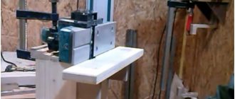
Making a stand
The stand will be made from an old Leningrad photographic enlarger, you can now get one at all sorts of flea markets, or if your relative was into photography:
Installed pantograph on the projection table:
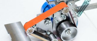
Illumination of the working area is required; as illumination, you can buy a ready-made module for microscopes, or make it yourself.
Of course I chose the second option, it’s transitional so to speak, I’ll order a good one
light. Everything was done on the knee in a matter of minutes from an SD tape:
Surprisingly, there is enough light, but it is not a panacea. In order to connect this whole thing to the action camera, I will use this adapter:
These adapter rings, if they are cheap, then come without an IR filter, and then we either order with this filter, or we farm, I collectively farmed from what I had, and I had one IR filter in my bins, don’t blame me, when I glued it my hand trembled and it went crookedly, but completely blocked the peephole:
It is worth considering that perhaps not all cameras will be compatible with this adapter shown above, for example, on my own, you will have to remove the front panel. In order to use it with the front panel, I bought extension rings for M12, like these:
One such ring will be enough for the front panel to fall into place (there is a confusion with the rings, they change the focal length very much, the microscope can only be used in the lower position of 200mm, everything higher will be out of focus). In general, I’ll say right away that there are special video modules that allow you to broadcast the image directly to the monitor, and you can also use video cameras for recording offenses; both of these camera representatives use the C-mount standard (28mm). An example of a camera sharpened for such observations:
I have a similar camera, it broadcasts in PAL. Now it’s difficult to say how many megapixels the sensor itself is, because documentation for it can no longer be found, but the picture via Video RCA shows a decent image for its age. We will check it too:
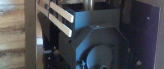
The analog camera will be connected through a DVR surveillance system, if anything it can be captured from it, but I still plan to work through EKEN. Next, you need to install the adapter ring that comes with the microscope lens. Here I was very lucky that the lens mount on the enlarger has the same diameter as the adapter ring, an interference fit was made, this is what happened:
Next, insert the lens there and center it with the clamping screws:
In the following pictures you can see what the installed cameras look like:
They fit very well, nothing interferes or touches anywhere, the only BUT
, the action camera is powered via microusb and connected via an HDMI adapter, the problem is that when the camera is active, power cannot be supplied to it due to the rather bulky HDMI adapter. To solve this problem, I ordered an angled cable for the camera:
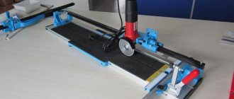
It doesn’t really bother me yet because there are 5 batteries per camera, but it’s necessary for convenience. I did not use the complete table, it is not convenient, it takes up a lot of space, I used a simple screw clamp to attach the pantograph stand to the desktop, this will save space and increase convenience; you can always move the stand with the microscope to the side. The photographs below show the maximum and minimum distance of the pantograph; while I was testing everything, I connected it directly to the TV for evaluation: For a CCTV camera
:
Maximum distance:
In general, I did not expect much from it, and immediately refused, very small things merge, despite the increase, the sensor is very weak for such things. For EKEN camera
:
Maximum distance:
The minimum distance is 200mm for both cameras, while narrower
you can work quite well, if it is too large, then it will be enough to adjust the pantograph to the middle distance and the work will be much easier.
Assembling the device
Quenching resistors with a nominal value of about 150 Ohms are placed in the breaks in the switching circuits of each of the lighting diodes.
To connect the supply wire, a mating part made in the form of a mini-connector is mounted on the ring.
The function of a moving mechanism that allows you to adjust the sharpness of the image can be performed by an old and unnecessary floppy disk reader.
You should take one shaft from the motor in the drive and then reinstall it on the moving part.
To make it more convenient to rotate such a shaft, a wheel from an old “mouse” is put on its end, located closer to the inside of the engine.
After the final assembly of the structure, a mechanism should be obtained that ensures the required smoothness and accuracy of movement of the optical part of the microscope. Its full stroke is approximately 17 millimeters, which is quite enough to sharpen the system under various soldering conditions.
At the next stage of assembling the microscope, a base (worktable) of suitable dimensions is cut out of plastic or wood, on which a metal rod selected in length and diameter is mounted. And only after that the bracket with the previously assembled optical mechanism is fixed on the stand.