Instruction card 33 - Oxygen cutting technology for metals
TO
category:
Gas welder's manual
Instruction card 33 - Oxygen cutting technology for metals
Next: Instruction card 34 - Rules for operating equipment for oxygen-flux cutting
Training and production assignments. I - separation manual oxygen cutting, II - surface oxygen cutting, III - machine oxygen cutting
Purpose of the tasks: to learn how to perform manual and machine cutting of low-carbon steels using acetylene and acetylene substitute gases as a combustible gas, to be able to choose the optimal cutting mode parameters.
Organizational guidelines. Prepare workplaces for oxygen cutting work, equipping them with equipment, fixtures and tools. Prepare low-carbon steel plates 20-30 mm thick, trimming corners, channels, I-beams, welded plates with seam and weld root defects.
I. Separation manual oxygen cutting
Plate cutting
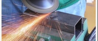
1. Place a low-carbon steel plate measuring 200 X 200 X 20 mm on supports so that the distance from the floor to the plate to be cut is at least 100-150 mm. 2. Heat the metal surface along the intended cutting line with the preheating flame of the cutter. 3. Using a metal brush, clean the heated surface from scale that has separated from the metal as a result of heating by the flame. 4. Mark the intended cutting line with chalk. 5. Set the required numbers of the outer and inner mouthpieces depending on the thickness of the metal being cut (20 mm). 6. Set the gas pressure on the acetylene and oxygen reducers depending on the selected mouthpieces and the thickness of the metal being cut. 7. Perform separation cutting. 7.1. Light and adjust the heating flame to normal. 7.2. Place the cutter mouthpiece at a distance of 3-mm from the metal being cut at an angle of 90° or with a slight inclination (5-10°) in the direction opposite to the cutting direction 7.3. Heat the surface of the plate end to a temperature close to the melting point; when cutting low-carbon steel, to a temperature of 1350–1360 °C. 7.4. After 5-10 s, open the cutting oxygen valve and begin the cutting process by moving the cutter along the cutting line. 7.5. After cutting the plate by 15-20 mm, set the inclination angle to 20-30 °C. 7.6. During the cutting process, move the cutter evenly at a constant speed; perform cutting at the optimal speed, as indicated by the flow of sparks flying out at an angle of 85-90° to the surface being cut; if the cutting speed is too low, the flow of sparks flies out in the direction opposite to the movement of the cutter, and if the cutting speed is too high, it will fly out at an angle of less than 85°. 7.7. At the end of cutting, close the cutting oxygen valve, then the flammable gas and heating oxygen valves.
Preparation of edges for welding
1. Repeat steps 1-6. 2. Prepare edges on metal 20 mm thick for V-shaped cutting. 2.1. Heat the surface of the end of the marked plate with a preheating flame of the cutter to the ignition temperature of the metal in oxygen (for low-carbon steel - 1350-1360 ° C). Maintain the angle of inclination of the cutter head to the product within 45°. 2.2. Apply a stream of cutting oxygen to the heated metal and, as soon as the metal is cut through to its full depth, move the cutter head along the cutting line. The angle (3 between the axis of the cutter head and the surface of the metal being cut at the beginning of the cutting process should be about 90°, during the cutting process - about 60-70°. 2.3. It should be borne in mind that the cut surfaces will not be the same. Surface b is always better, than surface A. The melting of the metal from above is explained by the fact that a greater amount of thermal energy of the heating flame is concentrated in this place, and the rounding of the lower edge is due to the action of liquid slag and an oxygen jet exiting towards surface A. In connection with the above, one must strive to ensure that Trimmings with surface a were thrown into waste.
Cutting holes on plates
1. Select a mild steel plate measuring 300 X 200 X 20 mm. 2. Clean the surface from scale and other contaminants. 3. Mark shapes such as triangle, square, ring with chalk. 4. Mark the centers of future holes to ensure the start of cutting, and in a ring-type figure, also mark a center for installing the trolley leg. 5. Drill holes with a drill with a diameter of 10-12 mm. 6. Place the plate on the cutting stands. Ensure free removal of cutting products. 7. Prepare the oxy-fuel cutting station for work. 8. Light the preheating flame of the cutter and cut out the shapes along the marking lines. 8.1. Place the torch flame above the edge of the hole, perpendicular and at a distance of 2-3 mm from the core. Heat the metal to its ignition temperature in oxygen. 8.2. Open the cutting oxygen valve and perform cutting. 8.3. Heat the edge of the hole located closer to the cutting direction to the required temperature. Direct a stream of cutting oxygen onto the heated surface and cut out a rectangular shape. 8.4. Place the support trolley with a compass on the cutter head, light the flame, and set the cutter to its original position to cut the ring along the outer contour. 8.5. Cut along the outer contour of the ring. Leave a section 40-50 mm long uncut. 8.6. Move the cutter to its original position above the hole. Cut out the inner contour of the ring around the entire perimeter. Upon completion of cutting, take measures to prevent the cutter head from skewing or falling due to the loss of a fulcrum by the compass and roller moving along the metal. 8.7. Remove the cart from the mouthpiece head and cut out the ring.
Cutting profile metal
1. Cut the corner. 1.1. Install a corner 40 X 40 mm (60X60 mm) so as to provide a distance under the corner of 100-150 mm for the free release of cutting products. 1.2. Set the required power of the heating flame. 1.3. Carry out cutting as shown in Fig. 4, a. First, cut through one shelf from bottom to top, then smoothly rotate the cutter, set it perpendicular to the second shelf and finish cutting. The cutting sequence can be changed. 2. Cut the I-beam. 2.1. You should start cutting from the top point of one of the shelves. Cut through the shelf to its full length and thickness. To do this, when the cutter approaches the beam post, reduce the cutting speed in order to cut through the post by a certain value I to point A. 2.2. Move the cutter to point A and position it perpendicular to the I-beam post. Heat the metal and cut through the stand to point B. 2.3. Place the cutter at the top of the second shelf and finish cutting.
Channel cutting
1. Place the cutter mouthpiece at an angle to the surface of the channel. Heat the edge and start cutting. 2. Carry out cutting in the same order, but place the cutter outside the channel contour.
Cutting square bars
1. Start cutting from a corner. Set the cutter head at an angle of approximately 45°. Heat the metal to ignition temperature. Move the cutter head to a vertical position. Start cutting. 2. At the end of the cut, tilt the cutter head 5-10° in the direction opposite to the cutting direction in order to cut the bottom corner first.
Cutting rolled round profiles
1. Heat the metal at the top point (zenith) of the circle to ignition temperature. Move the cutter head to position and release a stream of cutting oxygen onto the heated area of the metal. 2. Carry out separation cutting by moving the cutter head to positions 3-6. Maintain the distance of the mouthpiece from the metal surface constant. 3. Carry out cutting according to the diagram. 4. The productivity of the oxyfuel cutting process will increase if you cut several bars located one after another. The peculiarity of the cutting process is that at the transition points to each subsequent bar you need to tilt the cutter mouthpiece in the direction opposite to the cutting direction.
Pipe cutting
1. Mark the pipe using a flexible metal ruler and chalk. Encircle the pipe with a ruler, draw a marking line with chalk 2. Place the pipe on a roller stand. 3. Attach carriage 8 to the head of the mouthpiece. Cut grooves along the marking lines. Note the time it takes to heat the metal to its ignition temperature and the cutting time in each exercise (bring a groupmate with a stopwatch). After completing the exercises, compare the results and draw appropriate conclusions. 8.1. Start cutting the groove by heating the protruding metal formed by notching with a chisel. Maintain the speed at normal speed, as when cutting groove 2. 8.2. Start the line cutting process by heating the flat surface of the plate. Carry out cutting at high speed. 8.3. Start the cutting process along the line by heating and melting the end of a low-carbon filler wire with a diameter of mm on the metal surface, i.e., apply molten wire metal at the beginning of the cut and release a stream of cutting oxygen. Reduce the cutting speed compared to the speed of cutting groove 3. 9. Remove the metal surface to a depth of 8-10 mm with a rough and clean surface cut. 10. Cut out the defective area at the root of the weld on previously welded samples (metal thickness 10 mm). 10.1. Move 10-15 mm to the right from the defect. Cut a groove to the depth of the defect. Finish cutting approximately in the middle of the defective area. 10.2. Start cutting at a point 10-15 mm away from the defective area on the left, and finish cutting out the defect by moving the cutter flame from left to right.
Ill. Machine oxygen cutting
Cutting sheets at right angles
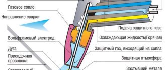
1. Place a clean 20mm thick carbon steel sheet on supports in a horizontal position. 2. Prepare for work the ASSh-70 machine, consisting of a column, hinged frame, copier, magnetic coil, cutters, or a portable machine “Mikron-2”, “MGP-2”. 2.1. Check the serviceability of the machine by external inspection and starting it at idle speed. 2.2. Install the copier on the machine console. 2.3. Set cutting mode parameters: oxygen and acetylene pressure, cutting speed, distance between the end of the nozzle and the metal surface, acetylene and oxygen consumption. 2.4. Light the preheating flame and adjust to normal. Launch a stream of cutting oxygen and make sure that the shape of the heating flame is not disrupted. 3. Cut out the part. 3.1. Bring the cutter to the starting point of the cut and position it so that the axis of the cutting channel of the mouthpiece is above the starting point of the cut. 3.2. Heat the metal until a pool of molten metal appears. 3.3. Turn on the cutting torch at a reduced speed and the cutting oxygen at a reduced pressure, then gradually increase the pressure of the cutting oxygen to the required one. In this case, the flame will gradually cut into the metal, the spray will be ejected by a stream of oxygen upward past the end of the mouthpiece (Fig. 10). By the time the normal pressure of cutting oxygen is established, the hole will be punched (the duration of burning the hole is about 0.5 minutes for a given metal thickness). After punching the hole, turn on the specified speed of the cutter (300-340 mm/min). 3.4. Upon completion of cutting the part, close the cutting oxygen valve and move the cutter to the starting point for cutting the next part. At the end of the lesson or when there is a break in work for more than a minute, extinguish the flame, close all gas valves, and disconnect the machine from the power supply.
IV. Oxygen cutting quality
1. Cutting quality is determined by cutting accuracy. The cutting accuracy depends on the skill of the cutter when cutting manually and increases when cutting on machines with manual electromagnetic, photoelectronic and program control. The magnitude of deviations from a given contour also depends on the length, thickness, condition of the sheet surface, the shape of the workpiece being cut, establishing the correct cutting sequence, etc. 2. The quality of separation cutting is characterized by the deviation of the cutting surface from perpendicularity and the width of the cut. Out-of-squareness can be reduced by precise cutting without the torch deviating from the vertical position. 3. The quality of the cut surface is assessed by the following parameters. 3.1. Surface roughness, i.e. the number of grooves per unit length and the depth of the grooves left by the cutting oxygen stream. 3.2. Deviation of grooves from straightness as a result of lag D from the axis of the mouthpiece of the cutting oxygen jet. 3.3. Melting the edges. 3.4. The presence or absence of burr.
GOST establishes three classes of surface quality for machine cutting: 1st class - highest, 2nd class - increased, 3rd class - ordinary. There are maximum tolerances for each class.
Types of gases for metal cutting
To begin with, let’s define that we call nitrogen and oxygen and air gas; air is also a gas.
When cutting with a laser (either CO2 or fiber), gas is supplied through the nozzle along with the laser in order to remove combustion products from the cutting zone or to help the laser process the material.
Nitrogen
If we are talking about nitrogen or oxygen, then there are many ways to store and supply gas to the machine, the most basic is a gas cylinder, we screw a reducer onto the cylinder to regulate the pressure and from the reducer we run a hose to the machine.
Air
A compressor is an AIR supply device. That is, only air. Air can be used to cut small thicknesses, on average up to 2-3mm. A filtration system is needed to ensure that the air that goes through the compressor to the machine is clean, without water or oil.
If the filtration system is bad, then small particles of water and oil fly out of the compressor along with the air, they settle on the protective glass of the laser head and the glass quickly fails. Also, the entire air path of the machine and head is polluted.
But that’s not all, in some machines air is also used to operate pneumatic systems, so it is worth distinguishing between the air supply to the cutting machine and for the operation of pneumatics.
Most often, the necessary cleaners are already installed inside the machine; nothing additional is needed.
Cutting steel with a gas cutter
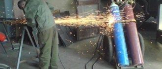
The handle of the gas cutting valve is slowly released down - a stream of oxygen is supplied, igniting the molten metal. If a violent reaction immediately begins to occur, then the steel has caught fire and you can continue to gradually increase the oxygen pressure until its stream cuts right through the material. When the reaction does not proceed, the metal is not heated enough to ignite in a stream of oxygen. It is necessary to add oxygen to the heating flame and allow it to heat the steel.
When the oxygen stream begins to cut, the cutter mouthpiece begins to slowly move along the cutting line. In this case, almost all processing products (molten slag, sparks) are blown away by a jet to the rear side of the cutting zone as shown in the video. If this flow comes back or slows down, then you need to reduce the speed of the cutter or stop it and heat the material even more (it is better to work very slowly than to try to cut too quickly). Cutting continues until the intended cut or separation of metal is completed.
Oxygen or nitrogen for cutting metal?
Oxygen cutting is the cheapest. Nitrogen cutting is much more expensive, but when processing almost all metals except ferrous metals, we use nitrogen if we want to preserve the properties of the metal.
You CANNOT cut stainless steel with oxygen . If we cut it with oxygen, the material will essentially burn, because combustion is nothing more than oxidation at high temperature, and oxygen is a combustion catalyst. Thus, we make rust from stainless steel, oxidize it, that is, we simply remove all its stainless properties.
And nitrogen is a non-flammable gas, it is inert, nothing burns in it, it performs another function - it protects the metal from oxidation, cools it and removes combustion products from the cut zone.
Ferrous metals are usually cut with oxygen.
Chernukha can also be cut with nitrogen, but this will be too expensive and unprofitable, and since it does not have stainless properties, there is no point in preserving them.
One more nuance - we use nitrogen to cut everything except titanium , which during laser cutting reacts with nitrogen, crumbles, and loses its structure and properties. To cut titanium you need argon .
Scope of application
Oxygen-arc cutting is most in demand during a complex of assembly and construction works, during which it is necessary to use the cutter in a repeated short-term mode, as well as on objects where the use of oxygen cutting is undesirable or completely unacceptable. In particular, this method is relevant for cutting metal under water. The technology is used for manual cutting of steel; it can be used for separating non-ferrous metals and alloyed alloys with small thickness, cast iron, and for batch cutting of similar products.
Manual oxygen-arc welding allows you to create a cut that is characterized by relatively low quality. Surfaces and edges have irregularities, deposits and roughness. Possessing high productivity and efficiency due to additional sources of thermal energy, the technology is often used during dismantling work, as well as work on grinding scrap metal for its subsequent processing.
Metalworking ordered from our company is carried out in the shortest possible time!
Why do you order oxy-fuel cutting from us:
- Creation of products from 1 hour
- Deferred payment to regular customers
- Payment upon delivery is possible
- Product quality complies with GOSTs, TUs and is confirmed by certificates
Gas pressure when cutting metal with a laser
So, the machine has two auxiliary gas connection sockets - an unregulated path for nitrogen or air and an oxygen path with a pressure regulator.
The first goes directly to the working head: that is, just as you set the pressure on the cylinder on the reducer, that’s how it works.
And the second - the oxygen path requires very precise pressure regulation, which is why there is a special regulator made by the Japanese company SMC. It allows you to set precise cutting pressure parameters directly from the program.
When we cut a material, it must first be punched. At the moment of this breakdown, the pressure should be 0.15-0.2 MPa, and during the cutting process, 0.5-0.6 MPa is enough and the machine must regulate this discrepancy in pressure.
If you pierce a material with oxygen at the same pressure as you use to cut it, then splashes of molten metal will fly, because... oxygen, as we found out above, is a combustion catalyst. There are no such problems with nitrogen; you can set the conditional 2 MPa and punch and cut at the same pressure.
Gas pressure regulator in a metal cutter
Returning to the pressure regulator - you cannot apply more than 1 MPa to it; in the best case, it will simply release excess pressure and you will have an excess consumption of oxygen; in the worst case, it will simply fail.
For cutting with nitrogen, the normal pressure is 1.6-1.8 MPa, and with oxygen - 0.5-0.6 MPa, i.e. gas consumption is almost three times less.
However, despite the fact that oxyfuel cutting is cheap, it is complex and requires experience in setting parameters.
A slight deviation in pressure, the wrong nozzle diameter - and you will have a bad cut.
But if you know how to work with oxygen, it turns out more efficiently and cheaper than nitrogen or air.
Speaking of air: what's the catch here?
CONTENTS Surface oxygen cutting of low-carbon steels
INTRODUCTION I. Technological part
1.1. Basic Cutting Techniques
1.2. Oxygen cutting equipment
1.3. Surface oxygen cutting
1.4. Accuracy and cutting quality
1.5. Safety precautions when performing horizontal work
II. Organizational and economic part
2.1. Workplace organization
2.2. Calculation of the volume of work and consumption of materials REFERENCES 1.2. Oxygen cutting equipment
For surface oxygen cutting, special cutters are used (Fig. 2). They differ from separation cutters in that their mouthpieces have a channel 2
larger diameter for a cutting oxygen jet and several channels
3
of small diameter for a heating flame;
the oxygen stream comes out of the mouthpiece at a lower speed than during separation cutting. The steel bar 4
serves to accelerate preheating at the beginning of the cut.
To quickly start a cutting oxygen jet, the cutter has a lever valve 5.
The support ring / on the mouthpiece is made of stainless heat-resistant steel.
With the help of such cutters, defective areas of welds are melted, the top of the seam is cleaned before back welding, the edges of seams are prepared before welding, and a number of other special works are performed. Fig.2.
Cutter for surface cutting and melting of defects When surface cutting, the nozzle is held at an angle of 15-20° to the surface (Fig. 3), as a result of which a shallow (up to 10
mm)
but fairly wide (up to 50
mm)
groove
Fig.
Fig. 3. Scheme of surface oxygen cutting and shape of melted grooves . Of Cylinder 3
contains 1.13
m 3
of oxygen under a pressure of 200
kgf/cm 2 .
4
surrounding the cylinder serves as a reservoir for fuel and contains 0.2
kg
of propane-butane.
Oxygen and propane-butane flow through hoses 5
and
2
into cutter
1
.
The entire device is attached to the carver's back with straps. The gas supply is sufficient to cut steel up to 19 mm
in 40
minutes, and
up to 50
mm
in 15
minutes.
Cutting can be carried out at external temperatures down to minus 20° C.
Fig. 4. Portable device for oxygen cutting using propane-butane 1.3.
Surface oxygen cutting Surface oxygen cutting is the process of removing a layer of metal with an oxygen jet.
Surface oxygen cutting differs from separation cutting in that the cutting oxygen jet is directed at an acute angle of 15-40° to the metal surface and moves at high speed along this surface (Fig. 5). Despite the external differences between surface and separation oxygen cutting, the essence of these methods is the same. In both cases, the preheating flame heats the metal to the ignition temperature, the metal is burned in a limited volume and the resulting slag is removed. Rice.
5. Scheme of surface oxygen cutting: 1 - nozzle, 2 - slag, 3 - groove.
In surface cutting, the heating source of the metal is not only the heating flame of the cutter, but also the molten slag, which, moving along the surface of the metal, heats up subsequent layers of metal. The slag produced by surface oxy-fuel cutting differs from the slag produced by separation oxy-fuel cutting due to its high content of unburnt iron.
Due to the reduction in heating time during surface oxygen cutting, the cutting speed increases and labor productivity increases.
Surface oxygen cutting is widely used in the metallurgical industry for removing surface defects in castings, in the welding industry for cutting out defective sections of seams and when performing repair work.
The process of surface oxygen cutting proceeds steadily only if the direction of movement of the cutter coincides with the direction of the oxygen jet. When the cutter moves evenly in the direction of the groove being formed, the preheating flame can be turned off.
There are two main methods of surface oxyfuel cutting: gouging and turning.
When gouging, the cutter, like a through cutter, removes a layer of metal of a certain width and length from the surface. The metal layer can be removed in one or several passes, depending on the depth of the layer being removed.
When turning, the cutter, like a turning tool, makes a translational movement along a round rotating workpiece. As a result of turning, a layer of metal of a certain depth is removed.
The advantage of the surface oxygen cutting process compared to other methods of removing surface layers of metal is its high productivity, which allows you to remove up to 5 kg of metal per minute with a manual cutter.
At the same time, during surface oxygen cutting, the metal layer adjacent to the surface being processed quickly heats up and cools down, as a result of which cracks may appear on the surface of high-carbon and alloy steels. The greater the size of the groove and the higher the content of carbon and other alloying elements in the steel, the greater the tendency to crack formation.
Heating of the metal to the ignition temperature is carried out by tilting the mouthpiece 70-80° to the metal surface. After the metal is heated, the mouthpiece is set at an angle of 15-40°, a stream of cutting oxygen is released and the cutter is moved at a given speed.
Table 1.3. Surface oxygen cutting modes
| Indicators | Mouthpiece number | ||
| 1 | 2 | 3 | |
| Cutting oxygen pressure, kgf/cm2 | 3-6 | 3-8 | 3,5-10 |
| Cutting speed, m/min | 1,5-8 | 1,5-1,0 | 1,5-10 |
| Oxygen consumption, m3/h | 18-40 | 20-55 | 30-75 |
| Acetylene consumption, m3/h | 0,9-1,0 | 0,9-1,0 | 0,9-1,0 |
| Groove dimensions, mm: width depth | 15-30 2-12 | 18-35 2-16 | 30-50 2-29 |
The depth and width of the groove may vary.
The depth of the groove increases as the angle of the nozzle increases, the pressure of cutting oxygen increases, and the speed of movement of the cutter along the groove decreases. The width of the groove is determined by the diameter of the channel of the cutting oxygen jet. Surface oxygen cutting modes are given in table. 1.3. 2.2.
Calculating the volume of work and consumption of materials Gas consumption during welding is also determined by the power of the torch tip and welding time. To calculate acetylene consumption per 1 m
weld, you need to divide the power of the tip by 60 and multiply the resulting result by the main welding time in minutes and by a factor of 1.05, which takes into account the additional consumption of acetylene for igniting and regulating the flame of the torch, tack welding, etc.
The filler wire consumption is calculated by the weight of the deposited metal. To determine the weight of the deposited metal, use the formula Q
=
CS 2 g/m
seam,
where Q
— weight of deposited metal per 1
m
of weld,
g; S
—thickness of the metal being welded,
mm; C
- coefficient (values of coefficient
C
are given in Table 2.2).
Table 2.2. C values
| Metal | Thickness, mm | Edge preparation | Coefficient C |
| Steel » | Up to 5 Over 5 | Without bevel 45° bevel » 35° » 30° | 12,0 10,0 8,0 7,0 |
| Copper » | Up to 4 Over 4 | Without bevel 45° bevel | 18,0 14,0 |
| Brass » | Up to 4 Over 4 | Without bevel 45° bevel | 16,0 13,0 |
| Aluminum » | Up to 4 Over 4 | Without bevel 45° bevel | 6,5 4,5 |
To obtain the total filler wire consumption to the obtained Q
you need to add 10-15% for losses from waste and spattering of the wire when it melts.
The welder and cutter must conserve oxygen, acetylene (calcium carbide) or other flammable gas, filler wire, and avoid their overuse, while ensuring high quality welding and cutting work.
To save welding materials, we can recommend the following.
1. The use of burners with economizers, which reduce gas consumption by turning off the burner during breaks in operation.
2. Use non-injector burners of equal pressure, which provide a constant composition of the mixture and do not require interruptions during the welding process to regulate the composition of the flame.
3. Widely use assembly and welding devices that allow welding without tack welds, which reduces the consumption of gases and wire.
4. Use special filler rods and wires that reduce welding defects (for example, LK62-05 wire for gas welding of brass, LK62-02 wire for gas surfacing of brass on ferrous metals, etc.).
5. Instead of powder fluxes, use paste fluxes applied in the form of coatings to the filler wire and rods, as well as to the edges of the metal being welded. Make wider use of self-fluxing filler wires (LK.BO wire when welding brass) and gaseous fluxes of the BM-1 type.
6. Use new designs of cutting nozzles with a parabolic shape of the cutting jet channel, increasing cutting speed and reducing oxygen consumption.
7. Carefully and correctly develop technology and cutting modes that ensure minimum specific gas consumption.
8. When air-arc cutting, use more resistant and slow-burning copper-plated electrodes in accordance with GOST 10720-64. 9. When plasma-arc cutting, use gases that provide the lowest consumption of tungsten electrodes, and also use high-power arc cutting, which increases the cutting speed and reduces the specific consumption of plasma-forming gases. Reduce auxiliary time for purging, adjusting gases and the duration of the pilot arc. Strive to reduce the cutting width, which reduces the specific consumption of electrodes and gases by increasing the cutting speed.
Air for metal cutting
If you are going to cut in air, you need to take care of a good filtration system, the cost of which can sometimes reach the cost of the compressor itself.
People think that I’m now going to grab God by the balls, not pay for gas, pay once for a compressor and that’s it – cheap and cheerful. But actually no, air cutting also costs money.
Disadvantages of Using Air to Cut Metal
It’s just a one-time and large investment. And the compressor also needs to be serviced - the oil needs to be changed. And it happens that the filters also fail, it works fine for three months, then suddenly it starts spitting. Condensation is flying from the receiver, that's all. And if you once clogged the duct, then installed air with normal filters, it still won’t help, because you will have to clean the duct itself, blow it with alcohol.
When working with air, you need to very thoroughly clean and dry the air path, because any moisture and oil that flies from the compressor will settle on the protective glasses and you will have to change them several times an hour.
For normal cutting with air, a pressure of 1.6-1.8 MPa is needed, but in order to achieve such an output pressure after all dryers and filtration systems, there must be 20-25 atmospheres before the filters. And such a compressor already costs normal money. Therefore, the cost of a compressor with a good dryer system will be quite expensive.
Think, maybe it’s more profitable for you to take a gasifier with nitrogen and just fill it once a month?
Let's summarize by air
Air is only relevant if you are cutting no more than 1.5 mm and if you are not chasing the color of the edge.
If you cut stainless steel with air, the end will not be white, but will be slightly yellow, since air contains 8-10 percent oxygen.
Air is not free. It's difficult and expensive. For this whole system to work properly, it is worth investing well in it. If you are cutting chernukha, then stainless steel, then one, then the other, then it is better to work with gases.
Security measures
Oxygen-arc cutting of metal belongs to the category of work with an increased fire hazard, which is performed by a cutter from among the electrical or electrical technological personnel. To ensure safety, the equipment is inspected at least once a year, and the work site is provided with primary fire extinguishing equipment. The performer must use a protective mask and special clothing during the technological operation.
see also
- Oxygen flux cutting
Gas equipment and workplace equipment at a metal cutter
- Gas can be supplied in 40 or 70 liter cylinder This is not very convenient, since they have to be changed frequently and additional time is spent on this.
- There is a matrix of cylinders - 25 cylinders tied with hoses. The cylinder matrix lasts longer, but it takes up more space and is more difficult to refill and transport.
- Maybe a gasifier is a large cylinder that contains gas in liquid form. This is why the gas from the gasifier is very pure. Moreover, it is more economical.
You should not chase gas purity three nines (99.999%), four nines (99.9999%). Ninety-nine hundredths (99.99%) is already enough. The rest is redundant, it is not financially feasible and will cost a fortune. OCH (very pure) or OSCh (extra pure) is enough, test it and decide what suits you best.
In the next article we will talk about the control system, software and show you the coolest functions of a metal cutter that greatly simplify the work process.
How to choose a better cutter?
Operating principle of a gas cutter.
We offer a block of useful information that will help you better navigate the specifications and technical characteristics of cutters in advance:
- Nipples are made of brass and aluminum. Brass options are more durable.
- If possible, choose models with aluminum rather than plastic handles. No matter how heat-resistant the plastic is, it will “float” in any case faster than aluminum.
- The handle should be quite massive: the diameter should be at least 40 mm.
- The valves should work well. This means turning without much effort.
- Lever-controlled devices are more convenient and economical to use, they save gas.
- Valve spindles must be made of stainless steel, and not brass, which is too short-lived. There are “combined” options; they occupy a middle position in terms of durability.
- The best materials for the cutter body are metals: brass, copper, stainless steel.
- We remember that acetylene cutters are more expensive. We monitor the material from which the parts that have direct contact with the flammable gas are made before mixing in the chamber. Attention! They should not be made of copper or its alloys, where the copper content is not less than 65%.
- If the design of the device is collapsible, this is better: it is easier to clean and repair.
- Only copper! Only copper outer mouthpiece!
- The correct internal mouthpiece for an acetylene-type cutting torch should also be made of copper. But in an oxygen cutter for metal it is made of brass. These are the nuances.
- Be sure to check with the seller the status of spare parts and consumables.
Service and repair of a metal laser machine
Many people can sell metal cutters, but not everyone has the same experience and knowledge as our managers and service employees.
Perhaps this article contained many terms that were unclear to you, do not be alarmed, we will clearly tell you about all the nuances and teach you how to operate the machine correctly. Our training lasts three days, during which time you will learn everything you need about the structure of the machine and its maintenance, we will teach you how to select settings for different types of materials of different thicknesses and show you how to work with cutting modes that simplify your work and help save time and materials .
We have successful experience working with various industries and therefore can teach you a lot, share our experience and give you unique advice on how to optimally set up your production.
Standards and dimensions
Welding using a welding torch with gas.
All standard measurements regarding gas cutters are specified in GOST 5191-79. Naturally, the weight and size of the devices are directly related to their power. Weight, for example, comes in only two sizes: the cutters of models P1 and P2 weigh 1.0 kg, and the high-power model P3 weighs 1.3 kg and not an gram more or less.
By the way, the type of combustible gas is also related to the power and size. If powerful P3 cutters operate only on a mixture of oxygen and propane, then smaller devices such as P1 and P2 can operate with any type of gas.
Insert gas cutters:
In addition to the classic models with different powers, there is a separate category - the so-called plug-in gas cutters with a special marking RV. According to GOST, they have a very strange name: tips for a gas torch for cutting metal. In general, they differ from traditional cutters: the mixing of the combustible mixture and oxygen is carried out at the tip itself.
These devices are much lighter in weight than cutters. PB1 weighs 0.6 kg, and PB2 and PB3 only 0.7 kg each. But don't let this apparent elegance fool you. Let's not forget that these are tips for the torch, complete with which they will weigh no less than conventional cutters. What is the advantage then?
The fact is that they can be purchased in addition to an existing burner and, thus, save some money. And the compactness of the entire set, packed in a special case. And one more important detail concerns the nature of flammable gas. The fact is that acetylene is much more expensive than propane.
But for metal welding, acetylene is much more desirable: a torch with it produces a flame with a temperature 400°C higher than the same one with a mixture of oxygen and propane.
Portable models: small ship – short voyage
Cutter device.
The market now offers many portable options for autogens - this is exactly how they are positioned. They are sold as an attachment for a compact collet gas cylinder. But in essence and the principle of operation, these are burners. Most of them provide a flame temperature no higher than 1300°C.
There are, of course, portable models of the “professional” range - collet cutters that produce a higher torch temperature - up to 2000 - 2500 ° C, which is generally close in performance to a classic oxygen-propane cutter. But physics is physics: even in these models there is no main component that cuts metal - an oxygen jet that oxidizes this very metal.
Where is a portable cutting torch good? When cutting easily fusible metals or alloys such as tin, brass, bronze, copper. But even these “children’s” options are not cut, but melted. Therefore, compact attachments - cutters are used more for soldering or welding small workpieces made of non-ferrous metals. These can be parts of household devices such as a refrigerator or air conditioner. Welding, not a cutter, in a word.
In any case, be careful when choosing such models; their proposed “portability” is not always justified in the end.
How it works
The device for implementing this technology has a very simple structure. This is a steel tube of suitable diameter through which oxygen is supplied. One end of the lance tube is connected through a valve and a flexible hose to an O2 source, and the other is applied to the surface to be treated. To activate the flame, the working end is heated to 1400 °C (an auxiliary heat source is used for this, for example a gas cutter), after which it begins to rapidly oxidize (burn), raising the temperature to 2000 °C and maintaining it without external heating. To ignite the flame, O2 is supplied at low pressure (about 1 atm), which, after the formation of a stable process, rises to operating parameters (5-6 atm).
As noted above, oxygen lance cutting of metals and concrete structures is often used in the metallurgical and construction industries. Using this method, the following operations are performed:
- drilling of metal and reinforced concrete products;
- scrap cutting;
- removal of casting profits;
- separation of thick slabs.
Since working with O2 carries a certain danger, such cutting must be performed using protective equipment: a shield, a mask and special equipment. Read more about the operating features of this gas and precautions in the article: Technical oxygen: production, operation and use in industry.