Date: April 8, 2014 During normal operation of pipelines, the direction of water flow is assumed to be in one direction.
To prevent the formation of backflow, check valves are used that have a one-way flow capacity and operate automatically.
Check valves are used when several pumps operate when combined into one network.
When the pressure in one line decreases, excess water pressure forms a reverse flow in it, which can cause damage to the pump and fittings.
The check valve automatically cuts off the emergency section from the reverse flow.
When choosing a check valve, its main technical characteristics are taken into account:
- Bore diameter DN (nominal diameter). A number of conditional passages are prescribed in GOST 28338-89;
- Pressure PN (nominal pressure) is the maximum excess pressure at which long-term and safe operation is guaranteed. A number of nominal pressures are prescribed in GOST 26349-84.
- In addition to domestic standards, international ISO, North American ANSI, and German DIN are used.
What is it and what is it for?
A check valve is one of the elements of protective pipeline fittings.
The main purpose is to prevent changes in the direction of water flow. It automatically closes the pipeline if the flow direction changes in the opposite direction.
Water check valve
Also performs the following functions
- When the water supply is turned off, it prevents its outflow through the riser
- Blocks hot water from entering the cold water supply system and vice versa
- Significantly reduces the likelihood of water hammer
- Increases the operating time of equipment (pumps, meters, etc.)
- Reduces the risk of broken connections in the plumbing system
How to make the right choice
For each hydraulic system, it is necessary to select a water check valve that is most suitable for operation under the specified conditions. It is necessary to take into account the nominal pressure in the system, installation dimensions and method of fastening.
In heating systems with metal pipes, it is advisable to install a rotary check valve, since constant circulation of water causes its contamination. Rotary check valves are insensitive to environmental contamination.
When using modern metal-plastic pipes, contamination is minimal, so it is possible to use a spring-loaded disc check valve.
Purified water flows through water supply systems; the diameters of the pipes are small. In this case, the best choice is a ball check valve with a coupling mount.
Where is it used?
A non-return valve is very useful in the water supply of a private home.
If for some reason the pump stops, it prevents water from flowing back into the well or borehole. In the event of a power outage or pump shutdown, there is no need to refill the system with water.
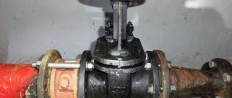
On water pipes.
The supply of hot and cold water in private and apartment buildings is carried out through different pipes. Sometimes different water pressure causes hot water to fill cold water pipes. The valve allows you to bring the pressure back to normal.
In front of the cold and hot water meter.
Helps protect against damage in the event of a water hammer.
At the inlet to the water heater.
The boiler is filled under pressure. When warming up and pressure increases, the displaced coolant will be directed back into the cold pipe. Prevents churn
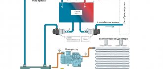
Scheme of water supply for a house with a storage tank
The presented scheme can be easily integrated into existing piping, both in water supply with one central pipeline and with several. Its compactness is due to the use of free space above the tank, in which the pumping station is suspended on brackets.
Figure 1 shows a water supply diagram for a private house with two central pipelines consisting of:
- 1 - tank 500 liters;
- 2 - pump;
- 3 — receiver (membrane tank);
- 4 - pressure switch;
- 5 — bronze five-point adapter;
- 6, 17 — pressure gauge;
- 7 — hose with reinforcing braid;
- 8 - check valve;
- 9 — float valve;
- 10 - American with external thread;
- 11 — American with internal thread;
- 12 - bronze transition from the container to the external thread;
- 13, 14 — MRN (male thread coupling);
- 15 — МРВ (internal thread coupling);
- 16 - bronze transition from external thread to internal thread;
- 18 — flow meter;
- 19 — mesh filter;
- 20 - 26 shut-off valves.
The suction discharge and distribution line is made of polypropylene pipeline and transitions with diameters of 32 mm (suction) and 20 mm.
Operating principle of a check valve
- The flow of water flowing through the pipes under pressure acts on the shut-off element and presses out the spring, which keeps the valve closed.
- After the spring has compressed, the valve opens and water flows freely through it in the desired direction.
- When the pressure in the water supply drops or when water moves in the opposite direction, the spring mechanism of the device moves the valve to the closed state.
- All the actions of the shut-off valve prevent the formation of backflow in the water supply system.
Operating principle of a check valve
Main settings
The check valve is characterized by quite a large number of different characteristics. The main ones can be called:
- Nominal diameter.
- Nominal pressure.
- Test pressure.
- Operating pressure.
- The pressure that occurs when the locking element opens.
- Bandwidth.
- Type of material used in manufacturing.
Some of the above parameters may be indicated by the manufacturer on the mechanism body. These must be taken into account when choosing the most suitable valve.
Design Features
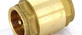
Housing material
The most common material used to make a check valve body is brass. This material is highly resistant to chemicals that may be present in water (mineral salts, oxygen, iron compounds, manganese, sulfur and others).
titanium, cast iron, steel, bronze mainly used in industrial systems
Plastic is used in polypropylene pipelines with water temperatures up to 90 degrees
Rubber or silicone sealing gasket.
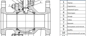
Check valve device
Shutter element
It comes in the shape of a ball, cone, or “plate”. Double-leaf check valves are also used in pumping stations and water supply systems. They have a shutter in the shape of two semicircular fragments. Most often made of brass
Return mechanism.
To return the shutter to the closed state, the device has a spring. Stainless steel is most often used to make the spring (an important element of the shutter). But there are also models where, under pressure, the shutter rotates on hinges.
Manufacturing materials
Check valves are made from a variety of materials, which must be selected based on the valve's operating conditions, the type of operating environment, and other requirements placed on them in specific industries.
The most popular materials for check valves are:
- Stainless steel;
- Various steel alloys;
- Brass;
- Plastics, mainly polypropylene.
What a check valve must be made of is largely determined by the type of fluid flowing through it, including its physical condition, level of corrosiveness, and required opening pressure and flow rate.
Types of check valve
Spring (lifting)
Its design is similar to a shut-off valve. With sufficient pressure, the valve rises up, opens the hole, allowing the flow to circulate. At low pressure it falls down onto the seat and the water path is blocked. All this happens automatically.
It is used only on horizontal pipes, with mandatory vertical axial installation.
Advantages of a spring valve. Repair is possible without dismantling, as it has a removable cover. Plus it can be used at high temperatures.
High tightness. Versatility, can be used in both private and industrial water supply systems.
One of the disadvantages of spring valves is sensitivity to dirt and mineral impurities contained in water, which can damage them. But this can be solved by installing a filter.
Ball valve
The locking element in this device is a metal ball. Sometimes the ball is covered with rubber for reliability.
If there is no pressure in the water supply, the ball, under its own weight, tightly blocks the passage hole and prevents the liquid from moving in the opposite direction. When water is supplied, the resulting pressure lifts the ball, opening the way for the water flow.
Ball check valve
Pros. Ball check valves can be installed in vertical and horizontal pipes
Simple design and absence of mechanical components increases service life.
However, it should be remembered that with an equal internal cross-section, the outer dimensions of a ball valve are larger than that of other types of valves.
Rotary or paddle
The valve received this name because of its design.
It is based on a metal disk (“plate”) and an axis with a spring. The axis of rotation is located above the through hole. When open, the disc is parallel to the movement of water; when closed, it is perpendicular. Under fluid pressure, the disc opens. When the pressure drops, the spring is activated, the disk turns and blocks the flow. rotates under fluid pressure. If the pressure drops, the spring is activated and the disk blocks the path of water
The disadvantage is that in valves of large diameter there is a strong impact when slamming, which can lead to rapid failure of the structure.
Rotary check valves are divided into two groups:
Simple - with a small diameter of up to 400 mm. Used in systems where shocks cannot greatly affect the operation of the hydraulic system and the valve itself
Impactless - valves with a special mechanism that ensures smooth closing of the disc. The downside is that they are more expensive.
Double check valve
This device has two locking segments, which are located on a rotating axis. The plates are located in the center of the passage hole.
Water moving in the right direction opens the doors. If the direction of flow changes, the plates, under the action of springs, close the passage of the liquid.
Butterfly valves come in a wide range of sizes so they can be installed on pipes of various diameters.
They are also recommended for installation in systems where high pressure is present.
Test pressure
To determine the main characteristics of the check valve, a test pressure indicator was also introduced. In technical documentation this indicator is designated as Rpr. The test pressure is characterized as follows:
- Water is supplied at temperatures ranging from 5 to 70 degrees Celsius.
- At this pressure, a hydraulic test is carried out. It allows you to determine strength and density.
All check valves must be tested. This is due to the fact that such fittings are critical elements of any pipeline.
Classification by installation method
Flanged valve
With this type of device, the return flange and the supply flange are welded to the valve body and a single structure is obtained.
This type of valve is mainly used in industrial systems for large diameter pipes.
Due to its large size, it can cause water hammer, since at the moment of closing, increased pressure is created in the system. To avoid this, systems use shock-free shutters with soft closing.
Advantages: ability to work in systems with water pollution. Application on main pipelines with large pipe diameters.
Wafer
These devices have virtually no mounting hardware. The valve itself is mounted between two flanges, at the ends of the connected pipes. A special seal is placed at the installation sites. After this, the flanges are tightened together with threaded connections (bolts or studs).
If installed correctly, the valve will be securely fixed. In terms of reliability, this type of connection is almost as good as a flange connection.
Coupled
The most common in household plumbing.
With this connection, the valve is connected to the pipe using a threaded coupling.
Pros: No need to use additional fasteners. Not suitable for large diameter pipes.
Components and operation
Design
General structural elements:
- collapsible metal case (galvanized), which has the best anti-corrosion properties and is resistant to active substances, including:
- spool chamber;
- coupling with internal thread for outlet/inlet;
Operating principle
The movable locking device moves freely inside the product. If the flow moves in the required direction, the ball moves away from the seat, opening the gap to the flow.
With reverse flow, the shut-off device is pressed against the seat, and flow becomes impossible, as shown in the photo.
Classification
Signs of classification.
1. Type of locking device:
- lifting - the lock moves up and down. After water is supplied from the pump, it opens slightly; in the absence of pressure, it closes due to spring pressure;
- rotary - locking doors that open under pressure or close with a spring when the pump is turned off;
- ball - a ball lock supported by a spring, which moves away from the flow, allowing water to pass through;
- disc - the lock slides along a pulley under a spring;
- double-leaf - shut-off valves fold under pressure or close when there is no flow.
For domestic purposes, lifting type products with a replaceable spring are usually used, due to the breakdown of which the device often fails.
2. Mounting type:
- coupling - due to two threaded transitions along the pipe. At home, thread from 15 to 18 mm (½” - 3”);
- flanged - due to a flange connection. In industry they are used for large pipes;
- wafer - by means of two flanges tightened with bolts. Used with large pipes;
- for welding - for long-term tightness.
3. Material:
- Brass - with good anti-corrosion properties, durable and unpretentious. Used on small pipes, often used in everyday life.
- Cast iron - for large pipes.
- Made of stainless steel - durable to any pipes, and also resistant to active substances, but expensive.
size 4:
- standard - for most pipes:
- 1 inch – the highest demand;
- ½ inch - less popular products due to low throughput;
- ¾ inch – for small diameter pipes;
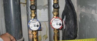
Do I need a check valve for a water meter?
If you turn on several taps at the same time in an apartment building, pressure drops will occur in the water supply system. To avoid this, it is enough to install a check valve on the water meter, which will equalize the pressure drops.
The internal space of the meter must be constantly filled with water. This requirement allows the hydraulic check valve to be fulfilled. This will allow the meter to not fail for a long time.
If the pressure in the cold water pipe is greater than in the hot one. The meter will also start counting cold water. This will result in an increase in your utility bill accordingly. The check valve prevents cold water from entering the hot water system.
Valves that reliably block the water flow and prevent movement in the opposite direction. They will help prevent the consequences of water hammer for the water meter. This significantly increases the service life of the device.
Nominal diameter
A check valve is installed on the pipeline. The nominal diameter is considered an important indicator and is designated DN. Among the features of this indicator we note:
- The indicator is measured in millimeters.
- Determines the standard size of pipeline fittings and is selected according to the internal diameter of the flow section.
- The indicator under consideration is used to unify the standard sizes of pipeline fittings.
The nominal diameter is taken into account in order to connect the shut-off element to the pipeline. All sizes are unified and indicated in GOST. Therefore, as a rule, there are no problems with selecting the most suitable valve.
Where to install
- If necessary, a check valve is installed where it is necessary to ensure flow movement in one direction.
- After the water meter, to protect against water hammer
- On hot and cold water pipes when used simultaneously. Due to the pressure difference, overflow through the mixer is possible
- At the water heater inlet to prevent heated water from escaping into the cold water supply system
- In front of the pump or pumping station to prevent the outflow of water in the event of a power outage or breakdown
- At the very inlet of the suction pipe
- In the anti-drip protection system of the dishwasher and washing machine
Where in the apartment should I install a check valve - video
How to install correctly
The easiest way to install a check valve is through a threaded coupling. Suitable for installation in the water supply system of an apartment or private house.
Work order (step by step instructions)
Select location, see above
Prepare fittings of the required diameter.
Wrap a sealant around the thread (linen, fum tape, thread)
Use a fitting to secure the check valve
Open the tap and check for leaks
If you are unsure or doubt your capabilities, call a plumber
It is important! There is an arrow on the valve body. The direction of the arrow must coincide with the direction of water flow in the pipeline
Even the most reliable shut-off valves fail over time. Therefore, you need to know how to remove the check valve yourself.
- First you need to turn off the water flow with taps
- if necessary, drain from the system
- Then unscrew the nuts.
- Dismantling flanges or fittings
- Remove the check valve.
- If possible, replace failed parts (for example, a spring)
- Reassemble in reverse order.
.
Attention! If the valve is installed near the water meter. You must act carefully so as not to damage the seal installed by the management company.
Installation of valves with a pumping station
When choosing a check valve, it is necessary to take into account its nominal pressure, flow capacity and bore diameter. All this data is contained in the technical passport. You can do the installation yourself, following the instructions for the pumping station. The manufacturer must indicate in it the recommended locations for installing all the necessary fittings.
Option for installing OK on a centrifugal pump:
Image gallery Photo from We select the part according to the size of the hose/adapter (for example, 1 inch), check the workmanship: there are no scratches, chips, or internal damage
The direction in which the water should flow is usually indicated by an arrow. If it is not there, then you can use the blowing method
Screw the check valve onto the adapter. To create a tight connection, use FUM tape or linen strand
To make the connection as strong and tight as possible, tighten the valve using a gas wrench
Step 1 - Selecting and Testing a Check Valve
Step 2 - Determine the correct installation direction
Step 3 - screwing the valve onto the threads of the adapter
Step 4 - tightening with a gas wrench
The main thing here is to find out the presence/absence of a check valve in the pumping station block. If it is already a standard element of the water supply installation, then there is no need to install this additional fittings. In this case, constipation will only reduce the throughput capabilities of the pipes, and there will be no benefit from it. It’s not worth spending money and time on installing an unnecessary element, which will also create even minor difficulties in the flow of water.
The standard installation locations for check valves are the lowest point of the suction pipeline and the entrance to the pressure line immediately after the pumping station
If the design of the water supply system assumes the possibility of emptying the pressure line or operating the pump in reverse mode, then the upper check valve cannot be installed after the water pressure unit. He simply will not allow such actions, blocking the flow of water to the water pumping unit.
The installation sequence of the “valve + valve” combination depends on the pump starting technology. There are models that are initially designed to be launched on a closed valve. In these cases, the check valve must be installed after the shut-off valve.
Manufacturers recommend installing a check valve in the “lower” position in all cases together with a coarse strainer. The water must first be purified from sand. The internal parts of the system will wear out faster from contact with abrasive particles.
It’s better to immediately take a reverse lock with a removable or non-removable mesh. It will protect the device from sand, and you won’t have to install an additional filter.
When choosing an installation point for a check valve, you must consider:
- direction of water flow;
- availability of fittings for subsequent repair and maintenance;
- restrictions on the strict horizontal or vertical installation of certain types of check valves;
- the presence of sand in the water, which can lead to clogging.
Spring check valves with a lifting shut-off element are least susceptible to contamination. The fastest and easiest way to install pipe fittings is with a wafer type connection. But more often, inexpensive analogues with flange or coupling mounting are chosen for water supply systems in private homes.
When using a submersible pump, a check valve is mounted at the end of the pipe lowered into the water intake, in front of the pumping device
When installing a check valve, it is important to install it correctly. The spool axis must be located strictly in a vertical position
And when installing a rotary product, the axis of rotation of the “flap” should always be above the center line of the water flow.
The arrow on its body allows you to control the direction of water flow and the correct location of the check valve. It is difficult not to notice it, and even more difficult to make a mistake with installing the locking device in the desired position.
Possible errors and problems during installation
The device may fail due to installation errors.
During the installation process, be sure to follow the instructions
It is advisable to inspect for problems once a month.
Possible problems:
No water flow
Incorrect installation. The arrow shows the direction of flow.
What to do: Disassemble and unfold the valve
During installation, the plug or the shutter retainer was not removed. This will result in the device not allowing liquid to pass through.
Solution: Dismantle, remove plug or retainer
The valve does not hold well
does not seal tightly.
A solid particle may enter and prevent the passage from being completely blocked.
What to do: First, try to wash off the trapped debris with a stream of water. You need to open and close the nearest shut-off valve several times. If this does not help, disassemble the check valve, rinse it well and reinstall it
The threaded coupling has burst.
This happens when there is a heavy load in the pipeline, a defective product, or too much sealing material is wound.
What to do: Can only be fixed by replacing the product
Tapping
After installing the check valve, knocking noises are heard. This can happen due to the larger valve diameter. Another option: installed too close to the pump.
Solution: in the first case, purchase a device with a smaller diameter. In the second, rearrange it to a more suitable place.
Operating pressure
In many ways, it is the pressure that determines the possibility of using a check valve. A similar indicator is designated Рр. Working pressure is characterized by the following features:
- Maximum water pressure at a certain temperature. It is worth considering that temperature affects the main elements of the valve, reducing strength and reliability as this indicator increases.
- Operating pressure affects the mechanism over a long period.
- Often a special graph is used to display the relationship between pressure and temperature. At certain temperature values, the operating pressure remains unchanged, but when a certain threshold is overcome, the indicator drops sharply.
This indicator is also indicated in GOST and can vary over a fairly wide range.
Advice and recommendations from experts
To avoid mistakes during installation, we recommend reading expert advice:
- The direction of the arrow on the valve body and the direction of fluid flow in the water supply must match.
- The device must be installed in places where there is easy access. This is necessary so that the check valve can be inspected or repaired in the future.
- Before installation, check the device for leaks.
- Valves made of steel and brass have a longer service life. Since they are more resistant to corrosion and pressure changes.
- It should be installed after the metering device.
So that the water check valve installed in the water supply system can function correctly for a long time. It is necessary to carry out installation according to the rules specified in the instructions
Nominal pressure
One of the most important parameters is the nominal pressure. It is designated PN. The features of this indicator include the following points:
- The nominal pressure is related to the maximum pressure of water at a temperature of 20 degrees Celsius.
- With this indicator, long-term operation of the check valve is allowed.
The device is classified in accordance with GOST. It is worth considering that the high nominal pressure provides a wide range of applications for the device. This indicator is indicated by the manufacturer and must be taken into account when choosing the most suitable design option.
Description of devices
The check valve looks pretty simple. Inside the structure there are the following main elements:
- a small spring that functions as a delay mechanism for the bolt mechanism;
- shutter with seal - can be made of durable plastic or steel;
- a metal body (usually dismountable for ease of maintenance), consisting of two threaded parts.
Today there are a large number of locking mechanisms. Taking into account the design, the device can be supplemented with the following auxiliary elements:
- stem;
- pin on hinges;
- ball bearings;
- springs;
- elastomers;
- disc levers.
To choose the right locking element, you need to take into account the design of the system and the main purpose of the installation.