Transformer is translated from Latin as “converter”, “converter”.
This is a static type electromagnetic device designed to convert alternating voltage or electric current. The basis of any transformer is a closed magnetic circuit, which is sometimes called a core. Windings are wound onto the core, of which there can be 2-3 or more, depending on the type of transformer. When an alternating voltage appears on the primary winding, a magnetic current is excited inside the core. It, in turn, causes an alternating current voltage with exactly the same frequency on the remaining windings. The windings differ from each other in the number of turns, which determines the coefficient of change in voltage. In other words, if the secondary winding has half as many turns, then an alternating voltage appears on it, two times less than on the primary winding. But the current power does not change. This makes it possible to work with high currents at relatively low voltage.
Types of transformers
Depending on the shape of the magnetic circuit, there are three types of transformers:
- Armored. It has a square shape with two side, one central and two transverse rods. In this case, only the central rod is effectively used. It is on this that the winding is put on. Therefore, the efficiency of this device is not very high. Forms two turns of magnetic field. This transformer is designed for heavy loads. This explains its very heavy weight.
- Rod. In some ways similar to the first type. The shape is half of an armored magnetic circuit. It consists of two lateral cores and two transverse ones. The magnetic field is single-turn, and, as a result, it has less power. The efficiency of such a transformer is 40%.
- Toroidal. It got its name due to its original shape. In mathematics there is such a thing as a toroidal surface. To put it simply, it is a voluminous circle or donut shape. Thanks to this shape of the magnetic core, toroidal transformers have the highest level of efficiency, approaching 100%. Therefore, such transformers are always smaller in size with the same power compared to other types. Due to the fact that the windings are evenly distributed over the entire area of the core, more efficient cooling of the turns occurs. Which, in turn, allows such devices to be loaded to the maximum without the risk of overheating.
Marking
Marking is the first stage, which is carried out if materials and tools are available. Careful research is important to determine the technical specifications.
It is acceptable to do it manually using special tables (but note that in this case you will have to calculate everything yourself using formulas).
You can also select markup using programs - there are some available for free on the Internet. But in this case, a novice radio amateur will not be able to understand the calculation algorithm and learn how to perform the frame independently, without the use of computerized equipment.
Plate materials
Transformer cores are made of either metal or ferrite. Ferrite, or ferromagnetic, is iron with a special crystal lattice structure. The use of ferrite increases the efficiency of the transformer. Therefore, most often the transformer core is made of ferrite. There are several ways to make a core:
- Made from stacked metal plates.
- Made from wound metal tape.
- In the form of a monolith cast from metal.
Any transformer can operate in both step-up and step-down modes. Therefore, all transformers are conditionally divided into two large groups. Boost: The output voltage is greater than the input. For example, it was 12 V, it became 220 V. Step-down: the output voltage is lower than the input. It was 220, but became 12 volts. But depending on which winding the primary voltage is supplied to, you can turn the step-down transformer into a step-up transformer, which will turn 10 A into 100 A.
How to speed up your workflow
Many radio amateurs have in their arsenal simple special units with which winding is made. In many cases, we are talking about simple structures in the form of a small table or table stand, on which several bars with a rotating longitudinal axis are installed. The length of the axis itself must exceed the length of the winding frame by 2 times. A handle is attached to one of the exits from the bars, allowing you to rotate the device.
Reel frames are placed on the axle , which are locked on both sides with limiting pins (they prevent the frame from moving along the axis).
DIY toroidal transformer
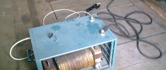
A toroidal transformer, or simply a torus, is most often made at home as the main part for a home welding machine and more. In fact, this is the most common type of transformer, first manufactured by Faraday in 1831.
Advantages and disadvantages of the torus
Thor has undoubted advantages compared to other types:
- Relatively small in size.
- Very strong output signal.
- The windings are short and, as a result, these devices are characterized by low resistance and very high efficiency.
- Thanks to their shape, they are easy to install and also easy to dismantle if necessary.
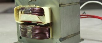
The simplest torus consists of two windings on its ring-shaped core. The primary winding is connected to the source of electric current, the secondary winding goes to the electricity consumer. By means of a magnetic circuit, the windings are combined and their induction is enhanced. When the power is turned on, an alternating magnetic flux appears in the primary winding. Connecting to the secondary winding, this flux generates electromagnetic force in it. The magnitude of this force depends on the number of wound turns. By changing the number of turns, you can convert any voltage.
Calculation of the power of a toroidal transformer
Making a welding toroidal transformer at home begins with calculating its power. The main parameter of the future torus is the current that will be supplied to the welding electrodes. Most often, electrodes with a diameter of 2–5 mm are sufficient for domestic needs. Accordingly, for such electrodes the current power should be in the range of 110–140 A.
The power of the future transformer is calculated using the following formula:
U - open circuit voltage
cos f - power factor equal to 0.8
n - efficiency equal to 0.7
Next, the calculated power value is compared with the cross-sectional area of the core using the appropriate table. For home welding transformers, this value is usually 20−70 kV. cm depending on the specific model.
After this, using the following table, the number of turns of the wire is selected in relation to the cross-sectional area of the core. The pattern is simple: the larger the cross-sectional area of the magnetic circuit, the fewer turns are wound on the coil. The direct number of turns is calculated using the following formula:
U is the current voltage on the primary winding.
I - secondary winding current, or welding current.
S is the cross-sectional area of the magnetic circuit.
The number of turns on the secondary winding is calculated using the following formula:
Toroidal core
Toroidal transformers have a rather complex core. It is best made from special transformer steel (an alloy of iron and silicon) in the form of a steel strip. The tape is pre-rolled into a dimensional roll. Such a roll, in fact, already has the shape of a torus.
Read also: How to check the suitability of a capacitor diode resistance
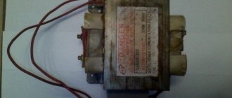
Where can I get a ready-made core? A good toroidal core can be found on an old laboratory autotransformer. In this case, it will be necessary to unwind the old windings and wind new ones onto a ready-made core. Rewinding a transformer with your own hands is no different from winding a new transformer.
Design
The first bipolar transformer was made by Faraday, and according to the data, it was a toroidal device. A toroidal autotransformer (brand Shtil, TM2, TTS4) is a device designed to convert alternating current from one voltage to another. They are used in various linear installations. This electromagnetic device can be single-phase or three-phase. Structurally consists of:
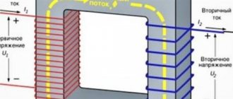
Photo - the principle of operation of the transformer
A device of this type is used in various audio and video installations, stabilizers, and lighting systems. The main difference between this design and other devices is the number of windings and the shape of the core. Physicists believe that the ring shape is the ideal design for an anchor. In this case, the winding of the toroidal converter is carried out evenly, as well as the heat distribution. Thanks to this arrangement of the coils, the converter cools quickly and even during intensive operation does not require the use of coolers.
Photo - finished TPN25
Video: purpose of toroidal transformers
Features of torus winding
The primary winding is made of copper wire in glass cloth or cotton insulation. Under no circumstances should rubber-insulated wires be used. For a current on the primary winding of 25 A, the wound wire must have a cross-section of 5-7 mm. On the secondary, it is necessary to use a wire of a much larger cross-section - 30-40 mm. This is necessary due to the fact that a much higher current will flow on the secondary winding - 120-150 A. In both cases, the wire insulation must be heat-resistant.
In order to properly rewind and assemble a homemade transformer, you need to understand some details of the process of its operation. It is necessary to correctly wind the wires. The primary winding is made using a wire of a smaller cross-section, and the number of turns themselves is much larger, this leads to the fact that the primary winding experiences very heavy loads and, as a result, can get very hot during operation. Therefore, the installation of the primary winding must be done especially carefully.
During the winding process, each wound layer must be insulated. To do this, use either a special varnished cloth or construction tape. The insulating material is pre-cut into strips 1-2 cm wide. The insulation is laid in such a way that the inner part of the winding is covered with a double layer, and the outer part, respectively, with one layer. After this, the entire insulating layer is coated with a thick layer of PVA glue. The glue in this case has a dual function. It strengthens the insulation, turning it into a single monolith, and also significantly reduces the humming sound of the transformer during operation.
Price overview
You can buy a toroidal transformer HBL-200 in any city in the Russian Federation and CIS countries. It is used for various audio equipment. Let's look at how much the converter costs.
Two compound roots “magnet” and “wire”, connected by the letter “o”, determine the purpose of this electrical device, created to reliably pass magnetic flux through a special conductor with minimal or, in some cases, certain losses.
The electrical industry widely uses the mutual dependence of electrical and magnetic energies, their transition from one state to another. Numerous transformers, chokes, contactors, relays, starters, electric motors, generators and other similar devices operate on this principle.
Their design includes a magnetic circuit that passes a magnetic flux excited by the passage of an electric current for further conversion of electrical energy. It is one of the components of the magnetic system of electrical devices.
The magnetic core of an electrical product (device) (Coil flux guide) is the magnetic system of an electrical product (device) or a combination of several of its parts in the form of a separate structural unit (GOST 18311-80).
What is the magnetic circuit made of?
Substances that are included in its design may have different magnetic properties. They are usually classified into 2 types:
To distinguish them, the term “magnetic permeability µ” is used, which determines the dependence of the created magnetic induction B (force) on the magnitude of the applied voltage H.
Read also: Simple DIY indoor TV antenna
The above graph shows that ferromagnets have strongly pronounced magnetic properties, while paramagnetic and diamagnetic materials have weak ones.
However, the induction of ferromagnets with a further increase in tension begins to decrease, having one clearly defined point of maximum value, characterizing the moment of saturation of the substance. It is used in calculations and operation of magnetic circuits.
After the cessation of the tension, some part of the magnetic properties remains in the substance and, if an opposite field is applied to it, then part of its energy will be spent on overcoming this part.
Therefore, in alternating electromagnetic field circuits, the induction lags behind the applied voltage. A similar dependence of the magnetization of ferromagnetic matter is characterized by a graph called hysteresis.
On it, the points Hk show the width of the loop, which characterizes the residual magnetism (coercive force). Based on their size, ferromagnets are divided into two categories:
1. soft, with narrow loop characteristics;
2. solid, having a high coercive force.
The first category includes soft iron alloys and permoloy. Cores for transformers, electric motors and alternating current generators are made from them because they create minimal energy consumption for magnetization reversal.
Hard ferromagnets made of carbon steels and special alloys are used in various designs of permanent magnets.
When choosing a material for a magnetic core, losses on:
eddy currents created by the action of EMF induced by magnetic flux;
aftereffect due to magnetic viscosity.
For magnetic core structures operating on alternating current, special grades of thin-walled sheet or coil steel are produced with varying degrees of alloying additives, which are produced by cold or hot rolling. Moreover, cold-rolled steel is more expensive, but has lower induction losses.
Plates or strips are created from steel sheets and rolls using mechanical processing methods. They are coated with a layer of varnish to protect and provide insulation. Double-sided coating is more reliable.
For relays, starters and contactors operated in DC circuits, magnetic cores are cast in solid blocks.
AC circuits
Among them, two types of magnetic cores are common:
The first type is made of two rods, on each of which two coils with high or low voltage windings are mounted separately. If you place one HV and LV winding on the rod, then large energy dissipation flows arise and the reactance component increases.
The magnetic flux passing through the rods is closed by the upper and lower yokes.
The armored type has a rod with windings and yokes, from which the magnetic flux bifurcates into two halves. Therefore, its area is twice the cross-section of the yoke. Such designs are more often found in low-power transformers, where large thermal loads on the structure are not created.
Power transformers require a large cooling surface for the windings caused by the transformation of increased loads. A rod diagram is better suited to them.
For them, you can use three single-phase magnetic cores, spaced by one third of the circumference, or assemble windings on common iron in their own cells.
If we consider a common magnetic circuit of three identical structures, spaced apart by 120 degrees, as shown in the upper left part of the picture, then inside the central rod the total magnetic flux will be balanced and equal to zero.
However, in practice, a simplified design located in one plane is more often used, when three different windings are placed on a separate rod. With this method, the magnetic flux from the outer coils passes through the large and small rings, and from the middle one through the two adjacent ones. Due to the formation of an uneven distribution of distances, a certain imbalance of magnetic resistances is created.
It imposes separate restrictions for design calculations and some operating modes, especially idle speed. But in general, such a magnetic circuit diagram is widely used in practice.
The magnetic circuits shown in the upper pictures are made of plates, and coils are put on the assembled rods. This technology is used in automated enterprises with a large machine park.
In small industries, manual assembly technology can be used using strip blanks, when a coil with a wound wire is initially made, and then a magnetic circuit from a transformer iron strip is mounted around it in successive turns.
Similar twisted magnetic cores are also created according to the rod and armor type.
For tape technology, the permissible material thickness is 0.2 or 0.35 mm, and for assembly with plates it can be chosen as 0.35 or 0.5 or even more. This is explained by the need to tightly wind the tape between layers, which is difficult to do manually when working with thick materials.
If, when winding the tape onto a reel, its length is not enough, then it is permissible to join the continuation to it and securely press it with a new layer. In a similar way, plates of rods and yokes are assembled in plate magnetic circuits. In all these cases, the joints must be made with minimal dimensions, because they affect the overall magnetic resistance and energy losses in general.
For precise work, they try to avoid creating such joints, and when it is impossible to eliminate them, they use grinding of the edges, achieving a tight fit of the metal.
When assembling a structure manually, it can be quite difficult to accurately orient the plates to each other. Therefore, holes were made in them and pins were inserted, which ensured good centering. But this method slightly reduces the area of the magnetic circuit, distorts the passage of power lines and magnetic resistance in general.
Large automated enterprises engaged in the specialized production of magnetic cores for precision transformers, relays, and starters have abandoned punch holes inside the plates and use other assembly technologies.
Laminated and butt structures
Magnetic cores created on the basis of plates can be assembled by separately preparing rods with yokes and subsequent installation of coils with windings, as shown in the picture.
On the right is a simplified butt assembly diagram. It may develop a serious drawback - a “steel fire”, which is characterized by the occurrence of eddy currents in the core to a critical value, as shown in the picture below on the left with a wavy red line. This creates an emergency situation.
This defect is eliminated with an insulating layer, which significantly affects the increase in the magnetizing flux. And this is already an extra loss of energy.
In some cases, it is necessary to increase this gap to increase the reactance. This technique is used in inductors and chokes.
For the reasons listed above, the butt assembly pattern is used in non-critical structures. For precise operation of the magnetic circuit, a laminated assembly of plates is used.
Its principle is based on a clear distribution of layers and the creation of equal gaps in the rod and yoke in such a way that during assembly, all created cavities are filled with minimal joints. In this case, the plates of the rod and yoke are intertwined with each other, forming a strong and rigid structure.
The previous top picture shows the laminated method of joining rectangular plates. However, oblique structures, usually created at 45 degrees, have lower losses of magnetic energy. They are used in powerful magnetic cores of power transformers.
The picture shows the assembly of several oblique plates with partial de-lamping of the overall structure.
Even with this method, it is necessary to monitor the quality of fit of the joining surfaces and the absence of unacceptable gaps in them.
Read also: Two switches for two light bulbs connection diagram
The method of using oblique plates ensures minimal losses of magnetic flux in the corners of the magnetic circuit, but it significantly complicates the manufacturing process and assembly technology. Due to the increased labor intensity of the work, it is used very rarely.
The laminated assembly method is more reliable. The design is durable, it requires fewer parts, and assembly is carried out according to a pre-prepared method.
With this method, a common structure is created from plates. After complete assembly of the magnetic circuit, it becomes necessary to install a winding on it.
To do this, you have to disassemble the already assembled upper yoke by removing all its plates one by one. To eliminate such an unnecessary operation, a technology has been developed for assembling the magnetic core directly inside the prepared coils with windings.
Simplified models of laminated structures
On low-power transformers, precise magnetic parameters are often not required. For them, blanks are created using stamping methods according to prepared templates, followed by coating with insulating varnish, most often on one side.
The left assembly of the magnetic circuit is created by inserting blanks into the coils from above and below, and the right one allows you to bend and insert the central rod into the inner hole of the winding. With these methods, a small air gap is formed between the joined plates.
After assembling the set, the plates are tightly compressed with fasteners. To reduce eddy currents with magnetic losses, a layer of insulation is applied to them.
Features of magnetic circuits of relays and starters
The principles of creating a path for the passage of magnetic flux remain the same. Only the magnetic circuit is divided into two parts:
2. permanently fixed.
When a magnetic flux appears, the movable armature, together with the contacts attached to it, is attracted according to the principle of an electromagnet, and when it disappears, it returns to its original state under the action of mechanical springs.
Alternating current constantly changes in magnitude and amplitude. These changes are transmitted to the magnetic flux and the moving part of the armature, which can hum and vibrate. To eliminate this phenomenon, the magnetic circuit is split by inserting a short-circuited turn.
A bifurcation of the magnetic flux and a phase shift of one part of it are formed in it. Then, when passing through the zero point of one branch, a force acts in the second, preventing vibrations, and vice versa.
Magnetic cores for DC devices
In these circuits there is no need to deal with the harmful effects of eddy currents, which occur during harmonious sinusoidal oscillations. For magnetic cores, sets of thin plates are not used, but are made in rectangular or rounded parts using the method of solid castings.
In this case, the core on which the coil is mounted is made round, and the body and yoke are made rectangular.
In order to reduce the initial traction force, the air gap between the separated parts of the magnetic circuit is small.
Magnetic cores of electrical machines
The presence of a movable rotor that rotates in the stator field imposes special features on the design of electric motors and generators. Inside them, it is necessary to arrange the windings through which electric current flows in such a way as to ensure minimum dimensions.
For this purpose, cavities for laying wires are made directly in the magnetic cores. To do this, immediately when stamping the plates, grooves are created in them, which, after assembly, represent ready-made lines for the windings.
Thus, the magnetic core is an integral part of many electrical devices and serves to transmit magnetic flux.
Most electronic devices require a certain type of power to operate, different from that supplied from an industrial network. One type of such device is a toroidal transformer. The device has found wide application in various fields of energy, electronics and radio engineering. Transformers are most often used in electrical networks and in power supplies for all kinds of electronic equipment.