The article is worth covering the topic of how a thyristor voltage regulator performs its work, the circuit of which can be viewed in more detail on the Internet.
In everyday life, in most cases, there may be a special need to regulate the total power of household appliances, for example, electric stoves, soldering iron, boiler, as well as heating elements, in transport - engine speed and other things. In this case, a simple and amateur radio design will come to our aid - this is a special power regulator on a thyristor.
Creating such a device will not be difficult; it can become the first home-made device that will perform the function of adjusting the temperature of the tip in the soldering iron of any novice radio amateur. It should also be noted that ready-made soldering irons on a station with general temperature control and other special functions cost much more than the simplest models of soldering irons. The minimum number of parts in the design will help you assemble a simple thyristor power regulator with wall-mounted installation.
It should be noted that the mounted type of installation is an option for assembling radio-electronic components without using a special printed circuit board, and with high-quality skills, it helps to quickly assemble electronic devices with average production complexity.
You can also order an electronic type of constructor for a thyristor-type regulator, and those who want to completely understand everything on their own should study some of the circuits and the principle of operation of the device.
By the way, such a device is a total power regulator . Such a device can be used to control total power or control speed. But first you need to fully understand the general principle of operation of such a device, because this will help you understand what load you should expect when using such a regulator.
How does a thyristor do its job?
A thyristor is a controlled semiconductor device that is capable of quickly conducting current in one direction. The word controlled means a thyristor for a reason, since with its help, unlike a diode, which also conducts the total current to only one pole, you can select a separate moment when the thyristor begins the process of conducting current.
The thyristor has three current outputs at once:
- Cathode.
- Anode.
- Controlled electrode.
To allow current to flow through such a thyristor, the following conditions must be met: the part must be located on the circuit itself, which will be under general voltage, and the required short-term pulse must be applied to the control part of the electrode. Unlike a transistor, controlling such a thyristor will not require the user to hold the control signal.
But all the difficulties of using such a device will not end there: the thyristor can be easily closed by interrupting the flow of current into it through the circuit, or by creating a reverse anode-cathode voltage. This will mean that the use of a thyristor in DC circuits is considered quite specific and in most cases completely unreasonable, and in AC circuits, for example, in a device such as a thyristor regulator, the circuit is created in such a way that the condition for closing the device is fully ensured . Any given half-wave will completely cover the corresponding section of the thyristor.
is most likely difficult for you to understand the diagram of its structure . But, there is no need to be upset - the process of functioning of such a device will be described in more detail below.
AC Models
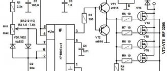
The AC regulator differs in that thyristors are used only of the triode type. In turn, transistors are standardly used in the field-field type. Capacitors in the circuit are used only for stabilization. You can find high-frequency filters in devices of this type, but rarely. Problems with high temperatures in models are solved using a pulse converter. It is installed in the system behind the modulator. Low-frequency filters are used in regulators with a power of up to 5 V. Control of the cathode in the device is carried out by suppressing the input voltage.
Stabilization of the current in the network occurs smoothly. In order to cope with high loads, reverse zener diodes are used in some cases. They are connected by transistors using a choke. In this case, the current regulator must be able to withstand a maximum load of 7 A. In this case, the level of maximum resistance in the system must not exceed 9 Ohms. In this case, you can hope for a quick conversion process.
Area of use of thyristor devices
For what purposes can a device such as a thyristor power regulator be used? Such a device allows you to more effectively regulate the power of heating devices, that is, load the active places. When working with a highly inductive load, thyristors may simply not close, which can lead to such equipment failing to operate normally.
Is it possible to independently regulate the speed of the device’s engine?
Many of the users who have seen or even actually used drills, angle grinders, which are otherwise called grinders, and other power tools. They could easily see that the number of revolutions in such products depends mainly on the overall depth of pressing the trigger button in the device . Such an element will be located in the thyristor power regulator (the general diagram of such a device is indicated on the Internet), with the help of which the total number of revolutions changes.
It is worth paying attention to the fact that the regulator cannot independently change its speed in asynchronous motors. Thus, the voltage will be fully regulated on the commutator motor, which is equipped with a special alkaline unit.
Introduction.
Many years ago, I made a similar regulator when I had to earn extra money repairing radios at a customer’s home. The regulator turned out to be so convenient that over time I made another copy, since the first sample was constantly installed as an exhaust fan speed regulator. https://oldoctober.com/
By the way, this fan is from the Know How series, as it is equipped with an air shut-off valve of my own design. Description of the design >>> The material can be useful for residents living on the top floors of high-rise buildings and who have a good sense of smell.
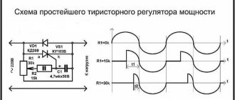
The power of the connected load depends on the thyristor used and its cooling conditions. If a large thyristor or triac of the KU208G type is used, then you can safely connect a load of 200... 300 Watts. When using a small thyristor, type B169D, the power will be limited to 100 Watts.
How does such a device work?
The characteristics described below will correspond to most circuits.
- A thyristor total power regulator, the principle and operating features of which will be based on the phase control of the voltage value, also changes the total power in the devices. This feature lies in the fact that under normal production conditions the load can be affected by approximate voltage indicators of the household network, which will change in accordance with the sinusoidal law. Above, when describing the principle of operation of a thyristor, it was said that any thyristor includes operation in only one direction, that is, it controls its half-wave from sinusoids. What could this mean?
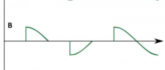
- If, using a device such as a thyristor, a load is connected over time at a strictly defined time, then the effective voltage indicator will be quite low, since half of the voltage (the effective value, which reproduces the load) will be much less than the light voltage. This phenomenon can be seen on motion graphs.
In this case, there is a certain area that will be under special stress. When the effect of the positive half-wave ends and a new period of movement with a negative half-wave begins, one of these thyristors will begin to close, and at the same time a new thyristor will open.
Instead of the words positive and negative wave, you should use the first and second (half-wave).
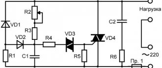
While the first half-wave begins to influence the circuit, a special charging of the capacitance C1 and also C2 occurs . The speed of their full charging will be limited by potentiometer R 5. Such an element will be completely variable, and with its help the output voltage will be set. At the moment when the voltage necessary to open diristor VS 3 appears on the surface of capacitor C1, the entire dinistor will open, and a current will begin to pass through it, with the help of which thyristor VS 1 will open.
During the breakdown of the dinistra, a point is formed on the general chart. After the voltage value passes the zero mark, and the circuit is under the influence of the second half-wave, the thyristor VS 1 will close, and the process will be repeated, only for the second dinistor, thyristor, and also the capacitor. Resistors R 3 and R 3 are needed to limit the total control current, and R 1 and R 2 are needed for the process of thermal stabilization of the entire circuit.
The principle of operation of the second circuit will be exactly the same, but it will control only one of the half-waves of alternating current. After the user understands the principle of operation of the device and its general structure, he will be able to understand how to assemble or, if necessary, repair the thyristor power regulator himself.
Replacing a triac in a dimmer
Hollow rivets can be removed using a 90° drill bit or side cutters. But in order not to damage the radiator, this must be done from the side where the triac is located.
The radiators, made of very soft aluminum, were slightly deformed when riveted. Therefore, I had to sand the contact surfaces with sandpaper.
- Screw M2.5x8.
- Spring washer (grower) M2.5.
- Washer M2.5 – fiberglass.
- Triac case.
- Gasket – fluoroplastic 0.1mm.
- Nut M2.5.
- Washer M2.5.
- Tube (cambric) Ø2.5x1.5mm.
- Washer M2.5.
- Radiator.
Since I used a triac that does not have galvanic isolation between the electrodes and the contact pad, I used the old proven isolation method. The drawing shows how it is implemented.
And these are the same parts of the galvanic isolation of the triac in its natural form.
To prevent the radiator wall from pressing through at the location where the triac is attached, a washer was placed under the screw head. And most of the head of the screw itself was ground off so that it would not cling to the handle of the potentiometer and power regulator.
This is what a triac isolated from the radiator looks like. To improve heat dissipation, thermal conductive paste KPT-8 was used.
What's under the dimmer housing?
Back in action.
DIY thyristor voltage regulator
This cannot be said that this circuit will not provide galvanic isolation from the power source, so there is a certain danger of electric shock. This will mean that you do not need to touch the regulator elements with your hands.
You should design the design of your device in such a way that, if possible, you can hide it in an adjustable device , and also find more free space inside the case. If the adjustable device is located at a stationary level, then it makes some sense to connect it through a switch with a special light brightness control. Such a solution can partially protect a person from electric shock, and will also relieve him of the need to find a suitable housing for the device, has an attractive external structure, and is also created using industrial technologies.
Construction and details.
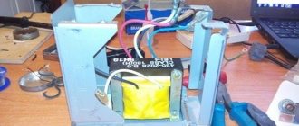
The regulator is assembled in the power supply housing of the once popular “Electronics B3-36” calculator.
The triac and potentiometer are placed on a steel angle made of steel 0.5 mm thick. The corner is screwed to the body with two M2.5 screws using insulating washers.
Resistors R2, R3 and neon lamp HL1 are dressed in an insulating tube (cambric) and mounted using a hinged mounting method on other electrical elements of the structure.
To increase the reliability of fastening the plug pins, I had to solder several turns of thick copper wire onto them.
This is what the power regulators I've been using for years look like.
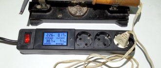
| to see this player. |
And this is a 4-second video that allows you to make sure that it all works. The load is a 100 Watt incandescent lamp.
Methods for regulating phase voltage in the network
- There are several ways to regulate alternating voltage in thyristors: you can skip or disable the output on the regulator as many as four half-cycles (or periods) of alternating voltage. It can be turned on not at the beginning of the half-cycle of the mains voltage, but with a certain delay. During this time, the voltage at the output of the regulator will be equal to zero, and the total power will not be transferred to the output of the device. During the second part of the half-cycle, the thyristor will begin to conduct current and a special input voltage will appear at the output of the regulator.
- The delay time in most cases is called the opening angle of the thyristor, since during the zero angle value almost all the voltage from the input will go to the output, only the drop in the open area of the thyristor will begin to be lost. As the total thyristor angle increases, the voltage regulator will significantly reduce the output voltage parameter.
- The regulating characteristic of such a device during its operation, during active load, is carried out especially intensively. At an angle of 90 degrees (electrical), the output from the connector will be half the input voltage, and at a total angle of 180 electrical degrees, the output will be zero.
Based on the principles and features of phase voltage regulation, it is possible to construct certain regulation, stabilization, and, in some cases, soft start schemes. To achieve a smoother start, the voltage should be increased over time from zero to the maximum value. Thus, during the opening of the thyristor, the maximum value should change to zero.
Purpose
Voltage booster transformers (linear regulators) are used to regulate voltage in individual lines or in a group of lines. They are used, for example, to improve the operation of networks that use transformers without load regulation. Linear regulators allow you to create an additional EMF in the network, which adds up to the network voltage vector and changes it. In Fig. Figure 1 shows a schematic representation of a boost transformer (linear regulator).
Figure 1 – Schematic representation of a linear regulator
Installing a voltage booster transformer allows you to equalize the voltage in the electrical network; eliminate voltage asymmetry in a certain section of the circuit; reduce the dangerous consequences of burning out the neutral conductor
Thyristor circuits
You can regulate the total power of the soldering iron quite simply if you use analog or digital soldering stations . The latter are quite expensive to use, and it is quite difficult to assemble them without much experience. While analog devices (considered to be essentially total power regulators) are not difficult to create yourself.
A fairly simple circuit of the device that will help regulate the power indicator on the soldering iron.
- VD - KD209 (or similar in its general characteristics).
- R 1 - resistance with a special rating of 15 kOhm.
- R2 is a resistor that has a special AC current rating of about 30 kOhm.
- Rn is the total load (in this case a special pendulum will be used instead).
Such a regulation device can control not only the positive half-cycle; for this reason, the power of the soldering iron will be several times less than the nominal one. Such a thyristor is controlled using a special circuit, which carries two resistances, as well as a capacitance. The charging time of the condensate (it will be regulated by a special resistance R2) affects the duration of opening of such a thyristor.
Manufacturing Features
There are several ways to make a control device. The easiest way is to purchase a kit containing a ready-made printed circuit board and radio elements necessary for DIY assembly. In addition to them, the kit contains an electrical and circuit diagram describing the sequence of actions. Such kits are called KIT and are intended for the most inexperienced radio amateurs.
Another way involves purchasing radio components yourself and manufacturing a printed circuit board if necessary. Using the second method, you can save money, but it takes more time.
There are many schemes of varying levels of complexity for self-production. But to make a voltage regulator, in addition to the circuit, you will need to prepare the following tools, devices and materials:
- soldering iron;
- multimeter;
- solder;
- tweezers;
- wire cutters;
- flux;
- technical alcohol;
- connecting copper wires.
If you plan to assemble a device consisting of 6 or more elements, then it would be advisable to make a printed circuit board. To do this, you need to have foil PCB, ferric chloride and a laser printer.
The technique of making a printed circuit board at home is called laser ironing (LUT). Its essence is to print a printed circuit board on a glossy sheet of paper, and transfer the image to the PCB using ironing. The board is then immersed in a ferric chloride solution. In it, open sections of copper dissolve, and closed ones with a translated image form the necessary connections.
Read also: What is babbit b83
When making the device yourself, it is important to be careful and remember about electrical safety, especially when working with a 220 V AC network. Usually, a correctly assembled regulator from serviceable radio components does not need adjustment and immediately starts working.
Analogues of KU202N
Like any other devices, the domestic thyristor KU202 has a foreign analogue , which, according to its parameters, belongs to the same category of components. Foreign manufacturers have long abandoned the production of this form factor in terms of power of thyristors in a metal case. Only elements in the TO220 transistor package will be available on the market. Therefore, in any case, you will have to make design changes to the board and the mounting location in particular.
Foreign analogues of the KU202N thyristor include the following devices:
The parameters differ slightly from the component described above, and the average current is 7.5 A. You can also use the newer Russian element T112-10 in the circuits. It also has a metal body with a threaded outlet, but its dimensions will be somewhat smaller.
Specifications
Let's consider the technical parameters of the KU 202e series thyristor. This series presents domestic low-power devices, the main use of which is limited to household appliances: it is used to operate electric furnaces, heaters, etc.
The drawing below shows the pinout and main parts of the thyristor.
Photo – ku 202
- Set reverse on-state voltage (max) 100 V
- Closed voltage 100 V
- Pulse in open position – 30 A
- Repeated pulse in open position 10 A
- Average voltage =0.2 V
- Set current in open position
Photo – thyristor Ku202n
The price of a thyristor depends on its brand and characteristics. We recommend buying domestic devices - they are more durable and affordable. In spontaneous markets you can buy a high-quality, powerful converter for up to a hundred rubles.
Thyristor KU202N belongs to the group of triode devices with a p - n - p - n structure. The junctions are created by planar diffusion of silicon. The thyristor is designed to switch high voltages using small levels through an additional output. Depending on the switching circuit, it can open or close, providing the required operating modes of the device. It is used in blocking systems, protection systems, servo drives, remotely controlled switching systems, chargers as a switch or charge current regulator.
You can buy the KU 202N thyristor in many other places, because it is a fairly common component. Moreover, its price is much lower than imported analogues. It can also be found in many Soviet devices, from power supplies to switching devices.
Chip contacts
Manufactured in a universal transistor package, allowing it to be placed on a board or heat sink. The most common model LM317 is found in the TO-220 case with the letter “T” at the end of the marking. The letter "t" indicates the housing type.
The pinout of the LM317 stabilizer is made using three contacts. If you look at the device from the front, the first pin on the left (Adj) is the adjustable pin, the middle pin (Vout) is the output, and the last pin on the right (Vin) is the input.
- Vin is a pin; it receives an input voltage that needs to be adjusted. For example, it may be supplied with 12V, which the device will step down to 10V at Vout.
- Vout is the pin to which the voltage is output. The surface of the heatsink is connected to this pin of the microcircuit.
- Adjustable (Adj) is a pin that allows you to adjust the output voltage through a trimmer resistor.
Found in various types of housings.
Contact numbers of different types of microcircuit housings.
Is it possible to regulate engine speed?
I think many of the readers have seen or used drills, angle grinders, which are popularly called “grinders,” and other power tools. You may have noticed that the number of revolutions depends on the depth of pressing the trigger button of the device. It is in this element that a thyristor power regulator is built in (the diagram of which is shown below), with the help of which the number of revolutions is changed.
Note! The thyristor regulator cannot change the speed of asynchronous motors. Thus, the voltage is regulated on commutator motors equipped with a brush assembly.