GOST 14098-2014
INTERSTATE STANDARD
WELDED CONNECTIONS OF REINFORCEMENTS AND EMBODIED PRODUCTS OF REINFORCED CONCRETE STRUCTURES
Types, designs and sizes
Welded joints of reinforcement and inserts for reinforced concrete structures. Types, constructions and dimensions
MKS 91.080.40
Date of introduction 2015-07-01
Preface
The goals, basic principles and basic procedure for work on interstate standardization are established by GOST 1.0-92 “Interstate standardization system. Basic provisions" and GOST 1.2-2009 "Interstate standardization system. Interstate standards, rules and recommendations for interstate standardization. The procedure for development and adoption, application, updating and information research center "Construction"
2 INTRODUCED by the Technical Committee for Standardization TC 465 “Construction”
3 ADOPTED by the Interstate Council for Standardization, Metrology and Certification (Minutes dated September 30, 2014 70-P)
The following voted for the adoption of the standard:
| Short name of the country according to MK (ISO 3166) 004-97 | Country code according to MK (ISO 3166) 004-97 | Abbreviated name of the national standardization body |
| Azerbaijan | AZ | Azstandard |
| Armenia | A.M. | Ministry of Economy of the Republic of Armenia |
| Belarus | BY | State Standard of the Republic of Belarus |
| Kyrgyzstan | KG | Kyrgyzstandard |
| Russia | RU | Rosstandart |
(Amendment. IUS No. 1-2022).
4 By Order of the Federal Agency for Technical Regulation and Metrology dated October 22, 2014 N 1374-st, the interstate standard GOST 14098-2014 was put into effect as a national standard of the Russian Federation on July 1, 2015.
5 INSTEAD GOST 14098-91
Information about changes to this standard is published in the annual information index “National Standards”, and the text of changes and amendments is published in the monthly information index “National Standards”. In case of revision (replacement) or cancellation of this standard, the corresponding notice will be published in the monthly information index “National Standards”. Relevant information, notifications and texts are also posted in the public information system - on the official website of the Federal Agency for Technical Regulation and Metrology on the Internet
AMENDED Change No. 1, approved and put into effect by order of the Federal Agency for Technical Regulation and Metrology dated 04/18/2019 N 142-st from 09/01/2019
Change No. 1 was made by the database manufacturer according to the text of IMS No. 6, 2022
INTRODUCED: amendment published in IUS No. 9, 2022; amendment published in IUS No. 1, 2022, effective from 08/23/2021
Amendments made by the database manufacturer
1 area of use
This standard applies to welded connections of rod and wire reinforcement, welded connections of rod reinforcement with sheet and shaped rolled products, performed in the manufacture of reinforcement and embedded products of reinforced concrete structures, as well as during the installation of prefabricated and construction of monolithic reinforced concrete structures.
The standard establishes the types, design and dimensions of the specified joints made by resistance and arc welding.
The standard does not apply to welded connections of embedded products that do not have anchor bars made of reinforcing steel.
Types of reinforcement connections
The connection of reinforcing bars is carried out in one of three ways:
- Mechanical;
- Overlapping, using special connecting elements;
- Using welding work.
Each of the above methods has its own advantages, disadvantages and features. It is worth noting them briefly.
The mechanical welding method involves the use of a hydraulic press and threaded and connecting couplings.
The manufacturing technology is as follows:
- The rods are “dressed” into threaded couplings.
- A hydraulic press allows you to compress the coupling around the rod, thereby securing it securely.
- Next, the structure is assembled using couplings. They can also be replaced with pipes with thick walls.
The advantage of mechanical assembly of fittings is the speed of work.
Some classes of reinforcement require a different joining method, such as lap jointing. It is worth noting that when working with overlapping reinforcing bars, a significant percentage of this material is lost.
There is also a significant advantage in this method of work - fasteners are needed, but additional tools and devices are not required.
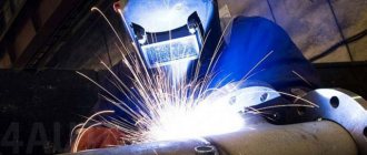
Finally, the third type of joining of reinforcement elements is by welding. The method is quite common and requires full professionalism.
For welding work you need:
- Welding machine;
- Electrode holder;
- Welding masks (shields), as well as protective glasses for them;
- Slag removal hammer;
- Chisel, regular hammer, plumb line, metal ruler.
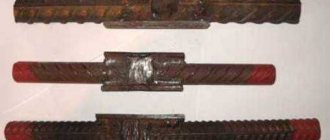
The joining of reinforcing elements is also carried out in various ways:
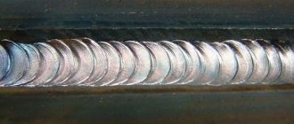
- long seams;
- multilayer seams;
- pointwise.
2 Normative references
This standard uses normative references to the following standards:
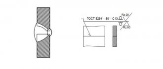
GOST 5264-80 Manual arc welding. Welded connections. Main types, structural elements and dimensions
GOST 6727-80 Cold-drawn low-carbon steel wire for reinforcement of reinforced concrete structures. Specifications
GOST 8713-79 Submerged arc welding. Welded connections. Main types, structural elements and dimensions
GOST 10922-2012* Reinforcement and embedded products, their welded, knitted and mechanical connections for reinforced concrete structures. General technical conditions
________________
* On the territory of the Russian Federation, GOST R 57997-2017 “Welded reinforcement and embedded products, welded connections of reinforcement and embedded products of reinforced concrete structures” is in force. General technical conditions".
GOST 14771-76 Arc welding in shielding gas. Welded connections. Main types, structural elements and dimensions
GOST 27772-88 Rolled products for building structures. General technical requirements
GOST 34028-2016 Reinforcing bars for reinforced concrete structures. Specifications
Note - When using this standard, it is advisable to check the validity of the reference standards in the public information system - on the official website of the Federal Agency for Technical Regulation and Metrology on the Internet or using the annual information index "National Standards", which was published as of January 1 of the current year, and on issues of the monthly information index “National Standards” for the current year. If the reference standard is replaced (changed), then when using this standard you should be guided by the replacing (changed) standard. If the reference standard is canceled without replacement, then the provision in which a reference is made to it is applied in the part that does not affect this reference.
(Changed edition, Amendment No. 1), (Amendment. IUS No. 9-2019).
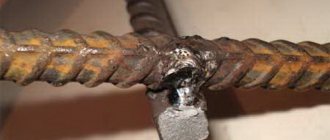
Bath welding
Bath joining is used if the cross-section of the reinforcing bars is large enough and reaches up to 10 cm.
Using bath joints, flanges are attached to metal pipes, multi-row reinforcement hollow “pillars” of any structures are connected, and other reinforcement frames are also manufactured.
Advantages
Products made using the bath method are especially durable and reliable.
The advantages of this manufacturing technology:
- During the work, conventional welding equipment is used.
- There is no need to rotate the structure. Work can be carried out at different angles, which is very convenient.
- Gamma rays can be used to check the quality of welds.
Welding Features
The features of this method include the following:
- The joining of rods, as well as structural elements, must be performed as accurately as possible. The minimum deviation value should not exceed 0.05 diameter. To do this, the structures are assembled in jigs, which allow the product to be fixed and thereby avoid deviations in the connection of the fittings.
- Bath welding makes it possible to join rods both vertically and horizontally.
Thus, there are several methods for connecting reinforcing rods. Welding joining is the most reliable option. In turn, this process can also be carried out in various ways, which makes it possible to choose the most suitable one. It will ensure high-quality welding of the product.
5 Technical requirements
5.1 When choosing rational types of welded joints and welding methods, you should be guided by Appendix A.
5.2 For the design of welded joints not provided for by this standard, working drawings should be developed with a technological description of welding conditions and a departmental regulatory document or enterprise standard that takes into account the requirements of current standards and approved in the prescribed manner.
5.3 In the manufacture of reinforced concrete structures, it is allowed to replace the types of connections and methods of their welding with equivalent ones in terms of performance in accordance with Appendix A.
5.4 The chemical composition and carbon equivalent value of reinforcing steels of classes A240, A400S, A500S, A600S, Ap600S, A800S, A1000S welded according to this standard must comply with the requirements of GOST 34028.
(Changed edition, Amendment No. 1).
5.4.1 (Deleted, Amendment No. 1).
5.5 Cold-deformed reinforcement must meet the requirements:
— class B500С — current regulatory documents*;
__________________
* GOST R 52544 is in force in the Russian Federation.
— class Vr-1 — GOST 6727.
5.6 Reinforcement of unmeasured length of classes Ap600S, A800S and At1000S, as well as waste of this reinforcement, can be used in welded reinforcement products and embedded parts of reinforced concrete structures. In this case, the reinforcement is used as A400C class reinforcement without recalculating the cross-section.
Reinforcement of class A600C is allowed for use as anchors for embedded parts as reinforcement of class A500C without recalculating the cross-section.
(Changed edition, Amendment No. 1).
5.7 The designs of cross-shaped reinforcement connections, their dimensions before and after welding must correspond to those shown in Figure 1 and Tables 2-3.
Figure 1 - Cross-shaped connection made by resistance spot welding
5.8 The ratio of the diameters of the rods should be taken for connections of type K1 - from 0.25 to 1.00, type K3 - from 0.50 to 1.00.
5.9 For connections of type K1, the amount of settlement (see Figure 1) is determined by the formula
;
where: - total thickness of the rods after welding at the intersection, mm;
— total size of dents, mm.
The relative precipitation values for type K1 compounds must correspond to those given in Table 2.
5.10 The designs of reinforcement butt joints, their dimensions before and after welding must correspond to those given in Table 4-10.
5.11 The designs of lap joints of reinforcement, their dimensions before and after welding must correspond to those given in Tables 11-13.
5.12 Designs of T-joints of reinforcement with flat elements of embedded products, their dimensions before and after welding must correspond to those given in Tables 14-17.
5.13 The main types, structural elements and dimensions of welded joints made of sheet and shaped metal products used to connect flat elements of embedded parts during the installation of reinforced concrete structures must meet the requirements of GOST 5264, GOST 8713 and GOST 14771.
5.14. For the connections given in Tables 7-8, sheet steel of class C235-C255 according to GOST 27772 should be used as the material for the brackets.
Table 2 - Designs of cross-shaped connections of K1-Kt reinforcement
| Designation of connection type, welding method | Reinforcement connection | Reinforcement class | , mm | The value ensuring strength is not less than that required by GOST 10922 for connections with a diameter ratio | The minimum value providing non-standardized | |||||
| before welding | after welding | 1,00 | 0,50 | 0,33 | 0,25 | strength | ||||
| K1-Kt | VR-1 (B500) | 3-12 | 0,35-0,50 | 0,28-0,45 | 0,24-0,40 | 0,22-0,35 | 0,17 | 30°-90° | ||
| В500С | 4-12 | |||||||||
| A240 | 5,5-40 | 0,25-0,50 | 0,21-0,45 | 0,18-0,40 | 0,16-0,35 | 0,12 | ||||
| А400С | 6-40 | 0,40-0,80 | 0,35-0,70 | 0,30-0,62 | 0,28-0,55 | 0,20 | ||||
| А500С | 6-40 | 0,40-0,60 | 0,35-0,50 | 0,30-0,46 | 0,28-0,42 | |||||
| А600С | 10-40 | |||||||||
| Note - Values that do not coincide with those given should be rounded to the nearest value specified in this table. | ||||||||||
Table 3 - Designs of cross-shaped connections of K3-Rp and K3-Mp reinforcement
| Designation of connection type, | Reinforcement connection | Reinforcement class | ; , mm | , mm | , mm | |
| welding method | before welding | after welding | ||||
| K3-Rp, K3-Mp | A240 | 10-40 | 0.5, but not less than 8 | 0.35, but not less than 6 | ||
| A400 | 10-28 | |||||
| А500С | 10-40 | |||||
| А600С | ||||||
| Notes 1 The value of temporary shear resistance in connections K3-Rp and K3-Mp is not standardized. If it is necessary to make connections with standardized strength, the dimensions are specified experimentally based on the results of shear tests (GOST 10922) and are drawn up in accordance with 5.2. In this case, it is not allowed to make connections of the K3-Rp and K3-Mp types with standardized strength on the construction site. 2 When mechanized welding of joints of the K3-Mp type, it is allowed to use reinforcement with a diameter of () 6 and 8 mm, as well as reducing the ratio of the diameters of the welded rods to 0.33. The use of these provisions is permitted under increased requirements for the acceptance of welded joints and mandatory compliance with the requirements of 5.2. | ||||||
Table 4 — Design of butt joint of S1-Ko reinforcement
| Type designation | Reinforcement connection | Reinforcement class | , mm | , mm | 10 | |
| connection, welding method | before welding | after welding | ||||
| S1-Ko | A240 | 10-40 | 0,85-1,0 | 90° | ||
| А400С | ||||||
| Ap600S, A800S | 10-32 | |||||
| А1000С | 10-22 | |||||
| А500С | 10-40 | |||||
| А600С | ||||||
| В500С | 10-12 | |||||
Table 5 - Designs of butt joints of S5-Mf and S7-Rv reinforcement
| Designation of connection type, | Reinforcement connection | Reinforcement class | , mm | , mm | , mm | 10 | , mm | , mm | , mm | |||
| welding method | before welding | after welding | ||||||||||
| S5-Mf, S7-Rv | А240, А400С | 20-40 | 0,5-1,0 | 12-20 12-16 | 5-12 | 90° | 10°-15° | |||||
| Notes 1 Dimensions in the denominator refer to the C7-Rv connection. 2 At ratio 1, linear dimensions refer to a rod with a larger diameter. | ||||||||||||
Table 6 — Designs of butt joints of S8-Mf and S10-Rv reinforcement
| Designation of connection type, | Reinforcement connection | Reinforcement class | , mm | , mm | , mm | , mm | 10 | , mm | , mm | , mm | |||||
| welding method | before welding | after welding | |||||||||||||
| S8-Mf, S10-Rv | А240, А400С | 20-40 | 0,5-1,0 | 5-15 3-10 | 8-20 | 90° | 40°-50° | 10°-15° | 20°-25° | ||||||
| Notes 1 When single-electrode welding, cutting rods with a bevel of the lower rod should not be carried out. 2 Cutting with a reverse bevel of the lower rod should be used when welding rods with a diameter of 32 mm. 3 Dimensions in the denominator refer to the C10-Rv connection. 4 With a ratio of 1, the linear dimensions refer to a rod with a larger diameter. | |||||||||||||||
Table 7 — Designs of butt joints of S14-Mp and S15-Rs reinforcement
| Designation of connection type, | Reinforcement connection | Reinforcement class | , mm | , mm | , mm | , mm | , mm | , mm | |||
| welding method | before welding | after welding | |||||||||
| S14-Mp, S15-Rs | A240 | 20-40 | 0,5-1,0 | 10-20 | 8°-10° | (0,35-0,40) | |||||
| A400 | |||||||||||
| At500 | 20-32 | ||||||||||
| А500С | 20-40 | ||||||||||
| А600С | |||||||||||
| Note - For 20-25 mm 6 mm, for 28-40 mm 8 mm. | |||||||||||
Table 8 — Designs of butt joints of S17-Mp and S19-Rm reinforcement
| Designation of connection type, | Reinforcement connection | Reinforcement class | , mm | , mm | 10 | , mm | , mm | , mm | , mm | , mm | |||
| welding method | before welding | after welding | |||||||||||
| S17-Mp, S19-Rm | A240 | 20-40 | 0,5-1,0 | 6-8 | 90° | 30°-40° | (0,35-0,40) | ||||||
| А400С | |||||||||||||
| А500С | |||||||||||||
| А600С | |||||||||||||
| Note - For 20-25 mm 6 mm, for 28-40 mm 8 mm. | |||||||||||||
Table 9 — Designs of butt joints of S21-Rn and S21-Mn reinforcement
| Designation of connection type, | Reinforcement connection | Reinforcement class | , mm | , mm | , mm | , mm | , mm | |
| welding method | before welding | after welding | ||||||
| S21-Rn, S21-Mn | A240 | 10-40 | , but >10 | , but >8 | , but >4 | |||
| A400 | ||||||||
| A600 | 10-32 | |||||||
| A800 | ||||||||
| A1000 | 10-22 | |||||||
| А500С | 10-40 | |||||||
| А600С | ||||||||
| В500С | 10-12 | |||||||
| Notes 1 Connections of reinforcement of classes Ap600C, A800C, A1000C should be made with offset linings, applying seams in a checkerboard pattern. 2 Double-sided seams of length 4 are allowed for connections of reinforcement of classes A240, A400C. 3 For reinforcement with a diameter of 25-40 mm, it is allowed, instead of reinforcement linings, to use reinforced brackets of the type shown in tables 7 and 8, for classes A400C and A500C - at least 6 in length, for class A600C - at least 8 in length. Internal size of brackets - there must be at least 2 pads, while the minimum cross-sectional area of the bracket is determined by the formula , where is the minimum cross-sectional area of the bracket-plate; - nominal cross-sectional area of the connected reinforcement; and is the temporary resistance of the reinforcement and brackets normalized by the standards, respectively. | ||||||||
Table 10 — Designs of butt joints of S23-Re and S23-Me reinforcement
| Designation of connection type, | Reinforcement connection | Reinforcement class | , mm | , mm | , mm | , mm | |
| welding method | before welding | after welding | |||||
| S23-Re, S23-Me | A240 | 10-25 | , but 8 | , but 4 | |||
| A400 | |||||||
| А500С | 10-25 | ||||||
| А600С | |||||||
| В500С | 10-12 | ||||||
| Notes 1 It is allowed to use connections of rods with any combination of their diameters within the limits specified in this table, while the dimensions , and in the connection of rods are taken according to the smaller diameter. 2 Double-sided seams of length 4 are allowed for connections of class A240 reinforcement. | |||||||
Table 11 — Designs of lap joints of N1-Rsh and N1-Msh reinforcement
| Designation of connection type, | Connection of reinforcement to plate | Reinforcement class | , mm | , mm | , mm | , mm | , mm | |
| welding method | before welding | after welding | ||||||
| N1-Rsh, N1-Msh | A240 | 10-32 | , but 4 | , but 8 | , but 4 | |||
| А400С | ||||||||
| Ap600S | 10-32 | , | ||||||
| А800С | but 5 | |||||||
| А1000С | 10-22 | |||||||
| А500С | 10-32 | |||||||
| А600С | ||||||||
| В500С | 10-12 | |||||||
Table 12 — Design of lap joint of N2-Kr reinforcement
| Designation of connection type, | Connection of reinforcement to plate | Reinforcement class | , mm | , mm | , mm | , mm | , mm | , mm | , mm | 3 | |
| welding method | before welding | after welding | |||||||||
| N2-Kr | A240 | 6-16 | (0,10-0,15) | , but not less than 4 | 90° | ||||||
| А400С | |||||||||||
| А500С | |||||||||||
| А600С | |||||||||||
| В500С | 6-12 | ||||||||||
Table 13 — Design of lap joint of N3-Kr reinforcement
| Designation of connection type, | Connection of reinforcement to plate | Reinforcement class | , mm | , mm | , mm | , mm | , mm | , mm | , mm | 3 | |
| welding method | before welding | after welding | |||||||||
| N3-Kr | A240 | 12-16 | (0,10-0,15) | , but not less than 4 | 90° | ||||||
| A400 | |||||||||||
| А500С | |||||||||||
| А600С | |||||||||||
| В500С | 12 | ||||||||||
Table 14 — Design of T-connection of T1-Mf fittings
| Designation of connection type, | Connection of reinforcement to plate | Reinforcement class | , mm | , mm | , mm | , mm | ||
| welding method | before welding | after welding | ||||||
| T1-Mf | A240 | 8-40 | 4 | (1,8-2,5) | 0,1 | 15° | 0,50 | 85°-90° |
| А400С, А500С | 8-25 | 6 | 0,65 | |||||
| 28-40 | 0,75 | |||||||
| В500С | 8-12 | 4 | 0,65 | |||||
Table 15 — Design of T-connection of T2-Rf fittings
| Designation of connection type, | Connection of reinforcement to plate | Reinforcement class | , mm | , mm | , mm | , mm | ||
| welding method | before welding | after welding | ||||||
| T2-Rf | A240 | 8-40 | 4 | (1,8-2,5) | 0,3 | 15° | 0,50 | 85°-90° |
| А400С, А500С | 8-25 | 6 | 0,65 | |||||
| В500С | 8-12 | 4 | ||||||
Table 16 — Design of T-joint of T11-Mz reinforcement
| Designation of connection type, | Connection of reinforcement to plate | Reinforcement class | , mm | , mm | , mm | , mm | , mm | , mm | , mm | ||
| welding method | before welding | after welding | |||||||||
| T11-Mz | А240, А400С, А500С, А600С | 12 | 8 | 0,5 | 0-1 | 4-5 | 22-26 | ||||
| 14 | 26-30 | ||||||||||
| 16 | 28-32 | ||||||||||
| 18 | 10 | 0-2 | 5-6 | 30-35 | |||||||
| 20 | 35-42 | ||||||||||
| 22 | 12 | 38-44 | |||||||||
| 25 | 46-48 | ||||||||||
| Notes 1 For fittings of classes A400C, A500C and A600C, the value is 0.55. 2 When using embedded parts with anchors made of A600C steel, you should follow the instructions of 5.6. | |||||||||||
Table 17 — Design of T-connection of T12-Rz reinforcement
| Designation of connection type, method | Connection of reinforcement to plate | Reinforcement class | , mm | , mm | , mm | , mm, at | , mm | at 12±1, mm | ||||
| welding | before welding | after welding | 6-7 | 8-26 | ||||||||
| T12-Rz | A240 | 8-40 | 6 | 1-2 | 2-3 | 50° | 0,50 | 2 | 4 | |||
| А400С | 0,75 | |||||||||||
| А500С | 10-40 | 8 | ||||||||||
| А600С | ||||||||||||
| В500С | 8-12 | 6 | ||||||||||
| Notes 1 At 12 mm, it is allowed to make connections without a weld. 2 When using embedded parts with anchors made of steel class A600C, you should follow the instructions of 5.6. | ||||||||||||
Tables 2-17 (Changed edition, Amendment No. 1).
Advantages of connecting reinforcement by welding
There are many advantages that allow you to choose welding joints as the most effective, reliable way to connect reinforcing bars.
For example, the ability to connect elements with different seams, as mentioned above. If you weld with extended seams, you can connect the rods with short or long overlaps, and also make one-sided or double-sided seams.
Multi-layer seams speak for themselves. First, the welding seam is applied to one side of the groove, then the mirror is applied to the other side.
Point joining is needed if a reinforced concrete product uses a structure with cross junctions. Not all brands of steel rods are suitable for spot welding. This is explained by the fact that the joints can quickly collapse due to the rapid spot hardening of the metal, which makes it very brittle.
Advantages of welding compared to other joining methods:
- Welding seams are the strongest.
- The impact strength of the product becomes much higher.
- A product created by welding is less susceptible to deformation, which means that the original shape of the product is better preserved.
- Reinforcing frames or meshes practically do not react to external environmental influences: sun rays, frost, etc.
Molds
To connect two strands of reinforcement, use a bracket-plate designed specifically for welding.
Copper baths or parts containing this metal are considered the most durable linings. The collapsible overlay is made from different grades of copper using casting, stamps and mechanical operations for processing blanks.
It is not recommended to use bronze or brass for making bathtubs. To ensure welding with small gaps, it is recommended to use a non-separable method for producing copper grooves. Such products can be used for welding more than 100 joints.