Typical installation mistakes
Most often, when installing electrical wiring, and in particular connecting a machine, the following mistakes are made:
- The power wire is inserted from below. Despite the fact that this electrical installation option is not prohibited by the PUE rules, we still do not recommend connecting the circuit breaker from below, especially since even on the front panel of the case there is a diagram in which the installation location of the fixed contact is at the top (as shown in the photo below) .
- The contacts are clamped too tightly with the fixing screw. This should not be allowed, because as a result, you can not only damage the cable core, but also deform the body of the product.
- The conductors are not connected correctly. A prerequisite is that the phase must be connected under the phase, zero under zero (if a two-pole switch is used). We immediately recommend that you familiarize yourself with the material: color coding of wires.
- Instead of one two-pole circuit breaker, two single-pole circuit breakers are used. This is strictly prohibited, because... phase and zero must be disconnected at the same time.
- When fixing the core, insulation gets into the seat. Be sure to strip the wire as much as required by the model data sheet. If you press down on the insulation with a screw, the contact of the conductor will weaken, as a result of which the core will heat up and further adverse consequences will occur. For this task, we recommend using a special tool for removing insulation.
- The choice of circuit breaker is incorrect; in particular, the product is not able to withstand the incoming loads. In this case, first you need to correctly calculate the cable cross-section and, according to the calculated characteristics, select the appropriate model.
- When calculating a suitable circuit breaker, the value is rounded up. For example, you calculated that the current load on the product is 19 Amperes. According to the simplest logic, novice electricians go to the store and purchase a device of the closest value for connection - 20 Amperes. This is a huge mistake, because... the calculated value is nominal, and it turns out that the protection will operate when the wiring is slightly overloaded. It is better to purchase a switch with a rating of 16 Amps, so the electrical wiring will last longer.
Another important point on which there is a lot of discussion is whether it is possible to connect the machine in front of the electricity meter or is this done only after it? The answer is that it is possible, and even necessary, the main thing is to buy a special box, which is sealed by energy sales representatives. Installing an input machine in front of the electric meter will allow you to safely replace the electricity control device both in a private house and in an apartment.
Here, in fact, are the rules for installing and connecting an electrical machine with your own hands. Now let's move on to the main topic of the article.
Design and purpose of the machine
Despite the name - “automatic”, this type of switch operates only in one direction - it opens the electrical circuit (if the nominal value is exceeded or there is an overload associated with the simultaneous activation of several powerful electrical appliances). There is only one way to turn on, that is, close the circuit - manually.
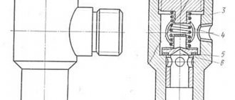
Unlike a simple single-key switch, an automatic device has a more complex structure. Schematically, the classic version (without an electronic unit) looks like this.
The terminals are located at the top and bottom, with the top one connected to a fixed contact, and the bottom one closely connected to a metal plate that acts as a thermal release. When the temperature of the material increases, the plate becomes deformed (+)
There are several ways to start the tripping process:
- manual control - on/off using a small lever;
- exposure to short circuit currents;
- excessive load – exceeding the rated current parameters.
To prevent the powerful thermal effect from burning the switch, an arc chamber (a set of insulated copper plates) is provided, which cools and breaks the electric arc.
Wiring
Ideally, if the machines are located next to each other on a DIN rail, then these distances can be measured simply by attaching a conductor so that the transition part from one machine to another forms a loop. This will allow the wire to exit the housing vertically.
The stripped area should be twice as long as the end of the wire, because we will have to make a small loop out of it, which will be used to connect the machine. You will need to put heat-shrink tubing on this loop or tightly wrap it with electrical tape at the place where the insulation ends. This will give our wire rigidity.
Then the loop must be inserted into the contact hole of the machine and tightened tightly. The cleaned areas should correspond to the number of circuit breakers. But we will be sure that the phase is separated correctly - the same for the apartment.
Standards for connecting the machine in the panel according to the PUE
Government authorities have requirements for shields and their installation that are specified in the PUE and must comply with GOST 51778-2001:
- the installed shield must comply with the documentation, which clearly reflects the number of machines and their power, as well as the class and degree of protection;
- the voltage symbol should be installed on the lid - 380V or 220V;
- the phase must be connected to a fixed contact;
- material of manufacture – metal or plastic coated with non-flammable paint;
- make markings on the wires indicating the devices that are connected;
- install jumpers from bus drives between the machines;
- There must be grounding of the box body. The case must have ears so that the electrical inspector can install the necessary seals.
Security measures
Wiring the electrical panel must be done only by disconnecting it from the power supply. Installation is carried out according to the drawn up diagram; deviation from it, with a high degree of probability, will cause a short circuit.
It is imperative to observe the polarity of the wires; cable marking greatly simplifies this task:
- The black wire corresponds to the phase;
- blue – zero;
- yellow-green – grounding.
Without RCDs it is impossible to provide the required level of protection, so installing them is mandatory.
By adhering to the safety measures listed above and knowing how to connect the circuit breaker in the panel, you will be able to carry out any electrical wiring upgrade in your home.
We assemble the shield in the apartment and house ourselves
An electrical panel in a private house, country house, or apartment performs a dual function: it provides input and distribution of electricity and creates safe operating conditions. If you want to understand a difficult issue, you can assemble the electrical panel yourself. The input machine and the meter must be installed by representatives of the electricity supply organization, but then, after the meter, you can assemble the circuit yourself (although they do not like to lose money). True, before putting the house into operation, you will need to invite them so that they are present during the start-up, check everything and measure the ground loop. All of these are paid services, but they cost much less than a complete panel assembly. If you do everything correctly and according to the standards, it will turn out even better on your own: after all, you are doing it for yourself.
Purpose of boxes for machines
Plastic and metal boxes perform the same function as distribution boards - they organize the operation of electrical equipment and serve for the electrical installation of protective devices. In the specialized literature you can find other names: box, box, shield, panel.
The main “filling” for filling the box is made up of electric machines, however, other protective devices - RCDs and difautomatic devices - can be located next to them.
There are no products for sale with pre-installed equipment. Low-voltage boxes are sold empty, and automatic protection devices are selected taking into account the characteristics of the network and installed according to the selected scheme
Large boxes contain indicators, switches, timers, differential relays. But to equip the network of a private house or one apartment, installation of additional equipment is not necessary.
If, in addition to protective equipment, an electricity meter is installed inside the box, then the panel goes from the distribution category to the metering and distribution category
Boxes are installed in apartments, on floor areas, as well as on the street, if it is necessary to connect a private home to the power supply line. They are varied in design, assembly and functions.
Instructions for connecting a two-pole circuit breaker
Now let’s try to figure out how to connect a two-pole circuit breaker to a 220 V household electrical circuit. This means that there will be 2 wires at the input - phase and zero.
The wire required for connection has 3 cores with a cross-section of 2.5 mm (VVGngP 3*2.5), therefore, the maximum permissible continuous current is 25 A.
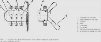
Working elements of the device
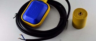
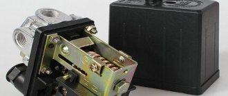
We have chosen a two-pole automatic protection device, which looks like this:
We will need four contacts, two of which are at the top (incoming), two at the bottom (outgoing). Fastening will occur using mounting screws that secure the pressure plates
There is a hint on the surface of the case - a connection diagram for the machine.
Based on the markings, we determined that the machine corresponds to the wire cross-section - C40. This means that a current of 40 A is the maximum response current of the device
The device is mounted on a metal plate – DIN rail.
If you look from the back, you can see a latch with which the machine is fixed to the DIN rail in one movement
Now that we've figured out the components, let's move on to the instructions.
Step-by-step photo instructions for connection
We turn off the voltage in the network and check its absence using a multimeter. We prepare wires that have double insulation. Three wires of different colors are hidden under the layer of external protection. The color correspondence is as follows: black – phase, blue – zero, yellow – ground.
We only need 2 wires - phase and neutral, the third (ground) will go separately. Remove the insulation 1 cm and insert the bare ends of the wires into the terminals
The phase should be on the left, zero should be on the right
Please ensure that some of the insulation does not come into contact - when heated, the cable may melt and cause damage to the device.
Carefully tighten the screws and proceed to grounding
To secure the grounding, we use a feed-through contact, which is fixed on the DIN rail in the same way as the circuit breaker itself. Insert the third wire and clamp it
The next step is to connect the outgoing wires, which are attached to the lower terminals.
In the same way, remove the insulation, insert the ends into the terminals and clamp them carefully so as not to damage the device body. Next we fix the ground wire
The connection is complete. All that remains is to apply voltage, move the control lever to the active position and check the operation.
What to do first
You bought a certain number of wires from the network of a new house, completed the wiring, its ends are connected to a control panel that has not yet been built into the wall, and there are automatic machines nearby. Remember: it is better to install one automatic packetizer or RCD at the entrance to the electric meter. There is no such thing as too much protection. Next, make a plan for connecting the wires to the arranged packages.
It is advisable to relieve the network by dividing it into zones - with heavy loads and normal ones: kitchen, living room-bedroom, corridor-toilet, veranda-basement. You will get confused with packets; the instructions for them describe currents, loads, and wiring cross-sections. Methods of contact with terminals and so on.
Reinforcing shears (bolt cutters): types, characteristics, main differencesHow a voltage control relay works: the principle of operation of the protection and the nuances of connecting a control relay for a house or apartment
What is a pulse relay: principle of operation, types, description of devices and connection diagrams. 155 photos of pulse-type relays and video installation instructions
Step-by-step instructions on how to connect a single-core wire
After you have purchased the RCD and all the necessary devices for installation, you can begin to work. It must be remembered that all stages of installation must be carried out sequentially and all safety measures must be taken.
Practical advice
Experienced electricians recommend installation in the following sequence:
- de-energize the shield. Check the presence of current using the indicator;
- care must be taken to ensure that no one unexpectedly turns on the electricity;
- the equipment must be firmly snapped onto the DIN rail;
- Electricians recommend connecting the device according to this principle - all incoming wires are at the top, and outgoing wires are at the bottom. This generally accepted scheme will help avoid confusion when replacing equipment;
- there should be no kinks in the wiring when connecting;
- disconnect excess parts of the cable with wire cutters;
- Carefully remove the insulation from the cable by 10 mm;
- Install the cable into the required terminals and secure it. It is necessary to monitor the clamping force - tightly twisted terminals will quickly lead to breakage of the switch;
- turn on the power supply;
- check the voltage access to the switch using an indicator.
Common Mistakes
Sometimes it happens that the power switch does not perform its functions, so you have to reinstall it again. To avoid malfunctions, you need to avoid the following installation errors:
- the insulation from the wire has come into contact. If the insulation is not removed before installation, this increases the risk of a short circuit that leads to a fire;
- connecting several wires with different cross-sections to one terminal. In this case, only a large cross-section core is tightened well, and thin wires have poor contact, which leads to melting of the housing and a fire. This happens when connecting various devices to the switch. To avoid this, you need to use jumpers between cables and devices. They are made from wires of the same cross-section;
- Do not connect copper and aluminum wires together. The device will become unusable due to the oxidation process when two metals are combined;
- You should not connect a straight wire to the terminal, but you need to bend it with a hook, which will increase the contact area and increase the performance of the device; such a cable is also more difficult to pull out of the device.
Connection errors and how to prevent them
When installing switchgear, beginners, and often experienced electricians, often make mistakes, which can subsequently lead to a fire or at least a power outage. The most common of them:
Stripper
- insulation getting under the terminal. In this case, it turns out that the contact is weakly clamped. At the junction, the contact resistance increases and the contact begins to overheat;
- stripping wires with side cutters or pliers. This is incorrect, because with this method of removing insulation, a small transverse cut is formed on the conductor, and the core may break off at the point of damage. To clean, you need to use a specialized tool - a stripper or at least a knife. Use a knife to remove the insulation as if you were stripping a pencil. With this method, no cuts are formed;
- installation with stranded wire. When the terminal is tightened, the wires move apart. The connection is loose, and since some of the wires do not come into contact, the cross-section of the wire at the attachment point is reduced. The cores of a multi-core wire must be terminated with special lugs, which are produced for each section. The ends are crimped with pliers or a special tool - a crimper;
- maintenance of multi-core wires. There is often an opinion that instead of mounting lugs, you can tin and solder the cores of a stranded wire. Solder is softer than copper and tends to melt under pressure. As a result, after some time the contact deteriorates;
- installation of wires of different sections under one terminal. Since the terminals are rigid, only a wire with a large cross-section can be reliably connected. A thinner one will not pinch. To connect several machines, a special comb bus is used. If there is no such bus, then take a piece of wire of the required cross-section. A jumper of the required shape is formed and only then the insulation is removed at the clamping points.
You might be interested in this Description of the push-button control station
Crimper
Note! Less critical are errors in the order in which protection devices are connected. It is considered correct to connect inputs into automatic machines or RCDs equally throughout the entire structure. The input should be placed at the top. In this case, the safety of servicing the switchboard is significantly increased.
The wrong choice of automation or poor-quality installation of distribution equipment not only reduces safety, but can also cause questions from regulatory organizations. It is better to entrust the work to professional electricians.
Drawing up an electrical panel diagram
An important step in installing an electrical panel is creating its diagram. There are several explanations for this. Let's say, if you plan to repair or modernize the wiring in your apartment in the future, using the diagram you can quickly establish what each machine and part in the panel is responsible for. You will also need the diagram when accepting work as an electrician. In addition, connecting wires with such a diagram on hand is much easier. You can either draw it manually or in specialized programs, and then print it.
The electrical circuit is created in several stages. The first step is to find out what kind of electrical system is in the house, then divide all points of electricity consumption into several categories. After this, based on the existing data, a shield diagram is created
It is extremely important that the diagram used symbols, which are described in detail in GOST 21.614 “Conventional graphic images of electrical equipment and wiring in the original”
So, as mentioned above, all work begins with determining the power supply and grounding system in the apartment, since the connection of the panel will depend on this. You can find out by looking at the sign on the floor or by going to the housing office. Often, three systems TN-C, TN-S, TN-C-S are installed in residential buildings.
It is worth immediately noting that the first system was created according to old GOST standards and was used in houses that were built before 1998. The TN-C system is represented by two-core copper or aluminum wiring. A three-phase cable (L) with one conductor PEN, in which ground and neutral were combined, went to the floor distribution board. The last two systems are used in modern homes. A three-core copper wire is laid in the apartment, and a cable with three phases (L), neutral (N) and PE ground (S) is connected to the switchboard.
Connecting reliable automation
In apartments, that is, where the electrical wiring is made according to a single-phase circuit, install one- or two-pole network releases. Consult an electrician which is better, because they come with different numbers of wires in a house or apartment
UPS for home: types, design and operating featuresWhat is an intermediate relay: design, principle of operation, device and application ideas (115 photos)
Homemade 12 volt power supply: selection of components and simple circuits for creating with your own hands. 130 photos of homemade universal blocks
At least superficially familiarize yourself with the insides of the packages. The main components in them are the automation control unit and the chamber in which the electric arc is extinguished. She appears at a couple of poles. When they are disengaged, an arc with a high temperature occurs, something like mini-welding.
The machine can be manually turned off if there is urgent work on the internal network. Or the contacts in it are burnt and you need to reconnect them to a free place. In automatic packaging machines there are an even number of pairs of contacts - from one to four.
If there are no free contacts, purchase a new automatic packetizer. It is advisable to have some in stock at home, they are inexpensive, but you won’t run to the store at night. Buy with operation indicators: red/green light.
How to connect the phase and neutral wires
Simultaneous disconnection of phase and neutral is justified especially in situations where three-phase voltage is introduced into a house or non-residential building. In such situations, there is a greater risk that one of the phases may short circuit to zero. This is a short circuit mode to which the machine protecting this phase must respond. But in those fractions of a second while it is triggered, an overvoltage will occur in the other two phases. That is, instead of the required 220 V, there may be all 380 V - the voltage difference between the two phases with a conventional three-phase connection.
Not a single household appliance is designed for such voltage, and the more powerful it is, the more current it passes, and the greater the likelihood of it burning out due to overvoltage. Where the fuse of a low-power device immediately blows, powerful equipment will still “tolerate” a heavy load for some time, and during this time the switching power supply or transformer may fail. Therefore, it is preferable to protect equipment such as boilers, dishwashers and washing machines with two-pole circuit breakers that cut two circuits at once.
Keep in mind that phase imbalance is also harmful to the source that powers the building. A generator, a transformer booth, a substation - all this will deteriorate very soon. For such purposes, there are special three-phase circuit breakers, which, in the event of a large imbalance or failure in one of the phases, can immediately turn off all three phases simultaneously. For more critical circuits, it is recommended to connect a four-phase circuit breaker, which also de-energizes the neutral wire.
Connection diagrams for the machine after the meter
Line separation is usually carried out using the following method:
- lighting line;
- line of low-current sockets;
- high load line.
High loads mean household appliances that consume high power - boilers, electric stoves, washing machines and dishwashers. These same devices must be protected using an RCD, since they operate in conditions of high humidity, and the slightest internal fault can cause current leakage to the housing.
RCD
Important! Electrical wiring intended for connecting lighting devices is usually the most lightly loaded and operates under normal conditions. It is not always advisable to install an additional RCD here.
Sockets in houses are characterized by the fact that they can connect both devices with low power consumption, for example, the power supply of an antenna amplifier, and high-power devices (a vacuum cleaner or an iron). The parameters of the protection devices are selected based on the maximum power of the connected devices.
Selection of RCDs and automatic devices
The circuit breaker provides short-circuit protection, but it is not capable of detecting leakage current that may flow into the electrical equipment frame when the insulation coating is broken or through the human body. For these purposes, a residual current device (RCD) or differential circuit breaker is connected to the panel.
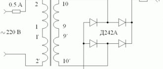
These devices are switching devices that constantly monitor the differential current of the electrical wiring, and if it deviates from the permissible value, a shutdown is performed. The principle of operation is clearly illustrated in the picture.
How does an RCD work?
The main purpose of these devices is to provide adequate protection in the event that a person becomes energized and to prevent fire that may be caused by a leak.
Main characteristics of the devices:
- rated current parameters (they must correspond to the circuit breaker or a higher value is allowed);
- operating voltage (220V or 380V, respectively, for single-phase and three-phase devices);
- The permissible leakage current parameter for household devices is considered safe 30mA.
In our circuit, it is necessary to install a 16A RCD with a permissible leakage current of 30mA (elements C – F). These differential protection devices do not need to be installed for hallway and kitchen lighting.
RCD for 16A
Types of circuit breakers
Modular circuit breakers in the electrical panel
There are 3 types of circuit breakers for the electrical network. They are able to work with loads of different sizes, and differ from each other in their design features.
- Air electric machines. These electrical devices can be equipped with 3-4 poles and can withstand a total current of up to 6.3 kA. Installed in electrical circuits with high power installations.
- Molded switches that are designed to operate in industrial networks with a current of up to 1 kA. They are made in a cast case, which is why they got their name.
- Modular AV devices are used in household networks where small currents flow. As a rule, they have 1-2 poles and a width that is a multiple of 1.75 cm.
Cast circuit breaker
There is another type of circuit breaker, which is called differential. Their difference from analogues is that the device is additionally equipped with an RCD.
An integral part of automatic machines are releases. They are necessary in order to break this circuit when the permissible values of the parameters of the electrical network are exceeded, stopping the supply of electricity. There are two types of releases - thermal and electromagnetic. In the first case, the machines operate almost instantly, while the latter will take a little time.
Methods for installing RCDs
There are two possible ways to install the device. The first option involves installing a common RCD in the electrical wiring diagram, immediately behind the meter and the machine. With one common RCD for an apartment or house, it is very difficult to find the place of current leakage through the insulation of the wires. Such a violation of insulation should be looked for throughout the apartment or cottage.
Variant of electrical wiring diagram with a common RCD and protective grounding in a single-phase network
In this case, the RCD will de-energize the entire apartment. In another option, several RCDs are installed, separately for each direction of electrical wiring, in the living room, kitchen, bedroom and children's room. This circuit of separate electrical wiring for rooms is assembled in the electrical panel in the hallway.
Several RCDs are installed in the same electrical panel. This option is of course expensive, but it has some advantages. Firstly, when the RCD is triggered, the network will be turned off in only one direction, and in the other part of the apartment the network voltage will remain. It will be easier to look for electrical damage in one room.
Electrical wiring diagram option with a separate RCD for sockets and protective grounding in a single-phase network
In a children's room, a separately connected RCD device will protect children from touching a dangerous socket faster than in the version of a common RCD. For the children's room option, an RCD with a shutdown current of less than 10 mA is installed. In the bathroom or kitchen where the washing machine is located, you need to install an RCD with a high response current (300mA - 500mA), because an RCD with a shutdown current of 10 mA will constantly turn off the kitchen.
The RCD is selected according to the optimal current for all loads in amperes. The response time of an RCD - a high-quality device - is up to 0.1 seconds, during which time an electric shock is not felt. The protection device must be checked for functionality by pressing the RCD test button once a month and after each emergency operation.
How to choose the right machine
The correct choice of circuit breaker is of great importance. Each device has its own parameters, such as rated current, operating voltage, number of poles, maximum short circuit current, time-current characteristic and other important values.
The response time of the device has a digital designation indicating at what current the normal operation of the circuit breaker is maintained. In home electrical networks, machines with numbers of 4500, 6000 and 10000 amperes are most often used. All technical characteristics are indicated by manufacturers directly on the device body. This also includes the connection diagram, as well as the symbol of the machine.
The main criteria for choosing a circuit breaker are the load power and the cross-section of the wires used. In addition, overload current and short-circuit tripping current are taken into account. As a rule, network overloads occur when devices and devices with a total power are simultaneously turned on, causing excessive heating of conductors and contacts. Therefore, the shutdown current of the circuit breaker installed in the circuit must be greater than or equal to the calculated one. Its value is determined as the sum of the powers of all devices used, divided by 220.
Installation and connection of elements
All modern automatic devices and RCDs have a unified mounting for a standard mounting rail (DIN rail). On the back they have a plastic stop that snaps onto the bar. Place the device on the rail, hooking it with the recess on the back wall, and press the lower part with your finger. Once clicked, the item is installed. All that remains is to connect it. They do it according to the scheme. The corresponding wires are inserted into the terminals and the contact is pressed with a screwdriver, tightening the screw. There is no need to tighten it too much - you can squeeze the wire.
They operate with the power off, all switches are turned to the “off” position. Try not to handle wires with both hands. Having connected several elements, turn on the power (input switch), then turn on the installed elements one by one, checking them for the absence of a short circuit (short circuit).
Connecting the input machine and RCD
The phase from the input is supplied to the input circuit breaker, from its output it goes to the corresponding input of the RCD (place a jumper with a copper wire of the selected cross-section). In some circuits, the neutral wire from the water is supplied directly to the corresponding input of the RCD, and from its output it goes to the bus. The phase wire from the output of the protective device is connected to the connecting comb of the machines.
In modern circuits, the input circuit breaker is set to two-pole. he must simultaneously disconnect both wires so that in the event of a malfunction, the network is completely de-energized: this is safer and these are the latest electrical safety requirements. Then the circuit diagram for switching on the RCD looks like in the photo below.
When using a two-pole input circuit breaker
To learn how to install an RCD on a DIN rail, watch the video.
In any circuit, the protective grounding wire is connected to its own bus, where similar conductors from electrical appliances are connected
Grounding is a sign of a secure network and doing so is vital. Literally
To learn how to properly connect an RCD, watch the video tutorial.
When assembling the panel yourself, please note that the input machine and the meter will be sealed by the energy supply organization. If the meter has a special screw onto which a seal is attached, then the input machine does not have such devices. If it is not possible to seal it, you will either be denied entry or the entire panel will be sealed. Therefore, inside the common panel, a box is placed in one or two places (depending on the size and type of machine), and the input machine is mounted in it. This box is sealed upon acceptance.
Individual automatic machines are installed on the rails exactly like an RCD: they are pressed against the rail until it clicks. Depending on the type of machine (one or two poles - wires), the corresponding wires are connected to them. What kind of machines there are, and how devices for one and three-phase networks differ, see the video.
After the required number of devices are installed on the mounting rail, their inputs are connected. As they said earlier, this can be done with wire jumpers or a special connecting comb. See the photo for what the wire connections look like.
The machines in one group are connected by jumpers: the common phase arrives
There are two ways to make jumpers:
- Cut the conductors into the required sections, expose their edges and bend them in an arc. Insert two conductors into one terminal, then tighten.
- Take a long enough conductor and strip off 1-1.5 cm of insulation every 4-5 cm. Take pliers and bend the exposed conductors so that you get interconnected arcs. Insert these exposed areas into the appropriate sockets and tighten.
They do this, but electricians say the quality of the connection is poor. It is safer to use special tires. Under them on the case there are special connectors (narrow slots, closer to the front edge), into which bus contacts are inserted. These tires are sold by the meter and cut into pieces of the required length using ordinary wire cutters. Having inserted it and installed the supply conductor in the first of the machines, tighten the contacts on all connected devices. Watch the video on how to connect machines in a panel using a bus.
A phase wire is connected to the output of the machines, which goes to the load: to household appliances, to sockets, switches, etc. Actually, the assembly of the shield is completed.
Operating principle of safety switches
As a rule, machines are turned off manually (remotely or using a drive), and if operating rules are violated, automatically. Violation of the operating mode means a decrease or increase in voltage to critical levels, the formation of overcurrents. Each machine is equipped with maximum voltage releases, and some with minimum voltage releases.
Depending on the functionality, circuit breakers are divided into reverse power, voltage reduction and maximum current circuit breakers.
Overcurrent circuit breakers are required to automatically open an electrical circuit when overloads within the established limits, as well as short-circuit currents, occur in it. They replace the fuse and switch, which provides selective protection in case of abnormal or emergency situations.
If the working environment differs from normal, for example, high air humidity, electrical structures are additionally required to be placed in special cabinets or boxes of chemical-resistant or dust-moisture-proof design.
Connection methods
Single-phase circuits
In order to answer the question posed earlier, one should proceed from the requirements of the PUE, which regulate the procedure for switching on the combination of an automatic machine plus an RCD. According to the provisions of this document, the protection device is connected as shown in the figure below.
Connection diagram for a single-phase RCD
When considering it, the following conclusions can be drawn:
- In a single-phase network, this device is almost always installed immediately after the meter;
- Line switches (automatic machines) are connected to its output, from which wiring is distributed throughout the apartment;
- The zero bus is connected from the corresponding output terminal of the meter to the second pole of the RCD;
Important! In this situation, special attention should be paid to the fact that the RCD is connected after the meter and before the machine with two wires: forward and reverse (this point is very important from the point of view of the possibility of its operation). You should also pay attention to the fact that the connection diagram for the uzo and the machine assumes the presence of a single-pole current switch. In this case, the neutral conductor coming from the meter or RCD is connected to a common ground bus (OGB), bypassing the machines, and from it is routed along separate lines paired with a phase wire
In this case, the neutral conductor coming from the meter or RCD is connected to a common ground bus (OGB), bypassing the machines, and from it is routed along separate lines paired with a phase wire
You should also pay attention to the fact that the connection diagram for the uzo and the machine assumes the presence of a single-pole current switch. In this case, the neutral conductor coming from the meter or RCD is connected to a common ground bus (OGB), bypassing the machines, and from it is routed along separate lines paired with a phase wire
Regarding the rules for connecting conductors to the device, the following should be noted. Like a circuit breaker, the incoming wires come from the top of the protection device, and the outlet wires from the bottom.
Three-phase network
A typical connection diagram for a three-phase device assumes the presence of 3 groups of input and output contacts, each of which forms a protection chain for one of the phases (see photo below).
Connection diagram for a three-phase RCD
Additional Information. The figure shows that in real power circuits the number of RCD input and output contacts is limited to four (three phases plus ground).
The latter is explained by the fact that the earth conductor for all three phase lines is common (it is highlighted in blue in the figure).
How to connect wires to a machine: How to properly connect machines in an electrical panel
How to connect a circuit breaker | Electrician's Notes
Hello, dear readers and guests of the Electrician's Notes website.
Almost everyone can connect a circuit breaker, but they often do it not quite correctly.
The fact is that there are constant disputes between electricians: some connect power to fixed contacts, and others to moving ones. There is no need to argue, open the PUE and read clause 3.1.6:
In almost all circuit breakers, RCDs and automatic circuit breakers, the fixed contact is located on top.
Here is an example of a single-pole circuit breaker VA47-29 C16:
Similarly, for a difavtomat AVDT 32, C16, 30 (mA):
From paragraph 3.1.6. we can conclude that the phrase “must be followed, as a rule” is most likely advisory in nature, i.e. does not prohibit. That is why many electricians neglect this point. In principle, this does not affect the operation of the machine in any way; it will still turn off in the event of a short circuit or overload - I have personally checked it several times.
Let us briefly consider the design of the modular single-pole circuit breaker BA47-29. The fact is that the surface of the fixed and movable contacts have dissimilar alloys. According to IEK factory tests, when switching alternating current, both contacts burn out evenly, so it is not critical which side you connect the power to. But when switching a direct current of significant magnitude, metal transfer from one contact to another is periodically observed, so in this case, power must be supplied only to the fixed contacts.
Personally, I am a supporter of ensuring that power is always supplied to the fixed contacts in order to bring uniformity (the same everywhere) to all circuit breaker wiring diagrams, especially in the residential sector.
At the same time, electrical safety during maintenance and operation of electrical networks will increase, personnel errors when bringing electrical equipment out for repairs will be reduced, etc.
Let's move on to practice.
Connecting single-pole and double-pole circuit breakers
As a rule, in single-phase 220 (V) networks, single-pole or double-pole circuit breakers are used. If the entrance to the apartment is made with two wires (phase L - red, zero PEN - blue), i.e. If you have a TN-C system (read about it in more detail), then the diagram will be as follows:
The supply phase is connected to terminal (1) of the input single-pole circuit breaker 40 (A), and then from terminal (2) it passes through a single-phase meter and is distributed among group circuit breakers 16 (A). The supply zero passes through the meter and is connected to the PEN zero bus.
If the entrance to the apartment is made with three wires (phase L - red, zero N - blue, ground PE - yellow-green), i.e. If you have a TN-CS or TN-S system, then the diagram will be like this:
In this case, the supply phase is connected to the input two-pole circuit breaker 40 (A) to terminal (1), and zero to terminal (3). From the output terminal (2), the phase passes through the counter, the input RCD 50 (A), 100 (mA) and is distributed among the group circuit breakers 16 (A). From the output terminal (4), the zero passes through the counter, the input RCD 50 (A), 100 (mA) and is connected to the zero bus N.
Connection diagram for three-pole and four-pole circuit breakers
To connect three-phase motors, three-pole circuit breakers are used, for example, VAMU-10.
The three-phase supply voltage (A,B,C) is connected to the fixed contacts (1,3,5), and the motor winding is connected to the moving contacts (2,4,6).
In three-phase networks with a TN-C, TN-CS or TN-S grounding system, three-pole circuit breakers can also be used.
In three-phase networks with a TN-CS or TN-S grounding system, it is allowed to install four-pole circuit breakers. They are connected in the same way, only there is another “N” pole added.
Connecting wires and cables to the machine
Each machine has its own requirements for connecting conductors: cross-section, length of insulation to be stripped, type of connection. Read your passport - everything is written there.
For example, to connect a VA47-29 C10 machine, you need to strip the wire core by about 0.7-1 (cm).
Then you need to insert it into the contact clamp and secure it with a screw.
After tightening, check the fixation of the wire by lightly tugging in different directions.
If you have a flexible wire, then it is better to use lugs of the appropriate cross-section.
Make sure that no wire insulation gets under the terminal clamp.
There is no need to tighten the screw too much, because... this may lead to deformation of the circuit breaker housing. When the housing is deformed, the position of the internal current-carrying parts changes, which leads to its rapid failure or increased heating.
How to connect several circuit breakers in one row?
If several machines are installed in one row in the panel, then it is advisable to connect them together not with wire jumpers, but with a special copper connecting busbar (SC) - a “comb”. It is cut to the required length and connects the phases to all machines in the row in the required sequence.
Read more about it in this article.
Source: https://esr-energy.ru/raznoe/kak-podklyuchit-k-avtomatu-provoda-kak-pravilno-podklyuchit-avtomaty-v-elektricheskom-shhite.html