Design and principle of operation of the pressure regulator
A gas pressure regulator or pressure reducing valve is designed to reduce the pressure in the line diverted from the main line and maintain this pressure at a constant level.
Pressure regulators are used to maintain the pressure required for the operation of pneumatic, gas or other equipment.
For example, pressure reducing valves are installed on gas cylinders and allow you to adjust the required pressure in the line discharged to the consumer. Reducing valves installed on cylinders are often called pressure reducers, since they reduce or reduce the pressure in the outlet line (reduction - reduction, reduction, reduction).
Pressure regulator device
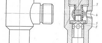
The schematic diagram of the pressure regulator is shown in the figure.
A spring 1 is installed in the valve body, the preload of which is adjusted by screw 2. The spring, through the membrane 3 and the pusher 4, acts on the seat valve 7, which is affected by the spring 8 in the opposite direction.
The outlet pressure depends on the size of the gap between valve 7 and seat 5; in addition, it acts on membrane 3 through channel 6.
The presented valve has two channels, inlet and outlet, which is why it is called two-line .
Pressure regulator with filter
This device combines a pressure reducing valve and a filter that cleans compressed air from impurities, dirt particles, and dust. More information about the design and operating principle of such a regulator (RDF) can be found here https://izpk.ru/reduktor-rdf-3-1-rdf-3-2.
Device
All components of the compressor pressure switch are assembled in a compact unit, covered with a plastic or metal case. The product includes:
- Inlet and outlet pipes.
- The sensitive element is a spring and a membrane.
- Stock. Connected to the membrane and placed inside the spring coils.
- Contact Group.
- Adjustment screws.
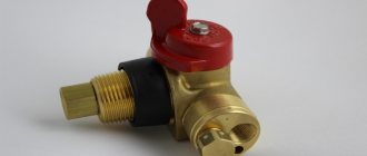
- Unloading and safety valve.
- Mechanical switch.
The elasticity of the spring, and, consequently, the sensitivity of the sensor, depends on the ambient temperature; most devices are designed to operate in the temperature range from -5 to +70 °C.
The unloading unit is designed to release air from the compressor cylinders after it stops. Thereby:
- its subsequent launch is facilitated;
- wear of piston group parts is reduced;
- the service life of the entire unit is extended.
When the unloading valve is activated in the silence that follows after the compressor stops, a sharp characteristic sound is clearly audible.
The mechanical switch serves for the initial start and final stop of the compressor. It has two positions: “On” and “Off”. “On” activates automatic operation systems. It transfers further control of the compressor to the pressure switch. The “Disabled” position prevents spontaneous starting of the motor when the pressure in the receiver drops below the set value.
The safety valve allows you to release excess pressure into the atmosphere in the event of a relay failure and avoid compressor breakdown in this case.
A thermal relay can serve as additional protection for the compressor motor. It is included in the automation unit; it disconnects the motor windings from the supply voltage in the event of an increase in current strength, indicating an overload of the motor.
Setting up an air compressor comes down to setting the operating pressure with an adjusting screw. The pressure regulator has values marked on it. Pressure can be controlled more accurately using a pressure gauge.
How does a pressure regulator work?
In the initial state, gas enters the valve inlet, flows in the gap between the seat and the valve, and enters the outlet. The amount of clearance is determined by the degree of spring preload, which is changed using an adjusting screw. It turns out that the outlet pressure depends on the inlet pressure and the size of the gap between valve 7 and seat 5.
If the outlet pressure increases, then under its influence the membrane will move and compress the spring, which, in turn, will move valve 7, and the flow area will decrease. The pressure loss across it will increase, which will cause the pressure in the discharge line to drop to the setting value.
If the pressure at the outlet of the regulator drops below the set value, the pressure with which the gas acts on the membrane will decrease, as a result, the preload of spring 1 will decrease. Valve 7 will move and increase the flow area. Losses on it will decrease, which will cause the pressure in the discharge line to increase to the setting value.
How does a regulator maintain pressure at a constant level?
It turns out that the pressure in the outlet line is maintained at a constant level due to changes in the amount of losses on the regulator. The regulator is adjusted using an adjusting screw, which changes the preload of spring 1; the control effect on the valve through the membrane is exerted by the gas pressure from the discharge line.
The regulator outlet pressure is defined as the difference between the inlet pressure and the pressure loss across the valve.
Connection and setup
The general diagram of the compressor installation shows that the pressure switch is located between the unload valve and the secondary control circuit. Most often, a pressure switch for a compressor has four threaded heads, one of which connects the device to the receiver, and the other connects a pressure gauge to monitor readings. The third can be fitted with a safety valve, and the last has a quarter-inch threaded plug in the thread. With a free connector, the user can install a control pressure gauge at his discretion.
The pressure switch is connected according to the following sequence:
- The device is connected to the unloading valve of the receiver.
- Install a control pressure gauge or plug.
- The engine control circuits are connected to the contacts.
- If there are fluctuations in the voltage network, then the connection is made through a surge filter, including when the contact power is greater than that available for the motor load current.
- If there is a need for this, the relay is adjusted through the adjustment screws to the required air pressure.
The connection is accompanied by checking that the voltage in the network matches the factory settings of the pressure switch. For example, a three-phase network of 380 Volts requires the use of a three-contact group, and for 220 Volts a two-phase group must be used.
The adjustment is made when the receiver is at least two-thirds full. The relay is disconnected from the network, the top cover is removed and the compression of the two springs is changed. The operating pressure limit is determined by an adjusting screw with an axis of larger diameter. On the board next to it there is a pressure mark in the form of the letter P and an indication of the direction of rotation of the screw, with the help of which the specified parameter is changed. The second screw helps set the required difference ΔP and has an indicator in which direction it rotates.
To speed up the adjustment process , in some cases the adjusting screw is pulled out, which changes the upper pressure level. Control is carried out according to the readings of the pressure gauge on the pressure regulator for the compressor.
Three-line pressure regulator
A regulator that, in addition to the input and output channels, also has an additional one - to vent air during a critical increase in pressure - is called a three-line regulator.
The design of this regulator differs from the design of a two-line regulator by the presence of a hole in the membrane, which opens if the pressure exceeds a critical value. Under normal conditions, the regulator works the same as a two-line regulator.
If the outlet pressure increases to a value sufficient to move the diaphragm to its highest position and open the relief channel. The gas is released into the atmosphere through this channel. The pressure in the discharge line is reduced until the spring force is sufficient to close the relief channel.
Since excess pressure is released into the atmosphere, three-line regulators of the presented design are used to regulate air pressure.
Thus, the principle of operation of the gas pressure regulator is similar to the principle of operation of the hydraulic pressure reducing valve shown in the video.
Operating principle of the pressure regulator
The design of the regulator is shown in the figure.
The main element of the pressure regulator is the measuring membrane 4, fixed in the housing 6. The rigid center of the membrane 7 is connected on one side by a spring 1 with a control screw 8 and a handle 5, and on the other side by a rod 3 with a poppet valve 9 supported by a spring 2. The rod 3 has a groove connecting the output of the gearbox to chamber B. Spring 1 acts on the membrane 4 (the change in the impact force is made by the handle 5), and through it the rod 3 on the poppet valve 9 and the support spring 2. If the force created by the control spring 1 exceeds the force created support spring 2, then valve 9 comes off the seat and passes compressed air from the regulator inlet to its outlet. Poppet valve 9 will be open until the total force created by the pressure in chamber A on the measuring membrane 4 (the pressure in chamber A is equal to the pressure at the outlet of the regulator), the force of the support spring 2 and the force of pressing the poppet valve created by the pressure in chamber B (pressure in chamber B is equal to the pressure at the outlet of the air reducer) will not exceed the force created by the control spring 1. The total force is determined by the output pressure and the force of the pressing spring 2, i.e. as soon as the pressure at the outlet of the regulator exceeds the set value, poppet valve 9 cuts off the outlet of the regulator from its input, thereby preventing further growth of the outlet pressure. When (due to the consumption of compressed air) the pressure at the outlet of the regulator drops below the set value, poppet valve 9 opens and the pressure rises to the set value, i.e. and the set pressure is maintained.
Gas reducer
- a device for reducing the pressure of a gas or gas mixture located in a container (for example, in a cylinder or gas pipeline) to operating pressure and for automatically maintaining this pressure constant, regardless of changes in gas pressure in the cylinder or gas pipeline.
GOST and marking
According to GOST 13861-89, gearboxes for gas-flame processing are classified: According to the principle of operation: direct and reverse acting gearboxes; By purpose and place of installation: balloon (B), ramp (R), network (C); By type of gas being reduced: acetylene (A), oxygen (K), propane-butane (P), methane (M); According to the number of reduction stages and the method of setting the working pressure: single-stage with a spring pressure setting (O), two-stage with a spring pressure setting (D), single-stage with a pneumatic pressure setting (Z). The gearboxes differ from each other in the color of the housing and the connecting devices for attaching them to the cylinder. Reducers, with the exception of acetylene ones, are connected with union nuts, the threads of which correspond to the threads of the valve fitting. Acetylene reducers are attached to the cylinders with a clamp with a thrust screw.
Main settings
Inlet pressure is usually up to 250 atmospheres for compressed (non-liquefied) gases and 25 atmospheres for liquefied and dissolved gases. The outlet pressure is typical 1-16 atm, although other modifications are also available. Gas consumption, depending on the type of reducer and its purpose, ranges from several tens of liters per hour to several hundred m?/hour.
Principle of operation
The operating principle of the gearbox is determined by its characteristics. Direct-acting reducers have a decreasing characteristic, that is, the operating pressure decreases slightly as gas is consumed from the cylinder; reverse-acting reducers have an increasing characteristic, that is, as the gas pressure in the cylinder decreases, the operating pressure increases. Gearboxes vary in design; the operating principle and main parts are the same for each gearbox.
Fig. 1 a - reverse-acting gearbox, b - direct-acting gearbox
Reverse action gearbox (Fig. 1a)
works as follows. Compressed gas from the cylinder enters the high-pressure chamber 8 and prevents the opening of valve 9. To supply gas to the burner or cutter, it is necessary to rotate the adjusting screw 2 clockwise, which is screwed into the cover 1. The screw compresses the pressure spring 3, which in turn bends the flexible rubber membrane 4 up. In this case, the transfer disk with the rod compresses the return spring 7, lifting the valve 9, which opens the hole for the passage of gas into the low-pressure chamber 13. The opening of the valve is prevented not only by the gas pressure in the high-pressure chamber, but also by spring 7, which has less force than the spring 3. Automatic maintenance of working pressure at a given level occurs as follows. If the gas intake into the burner or cutter decreases, the pressure in the low-pressure chamber will increase, the pressure spring 3 will compress and the membrane 4 will straighten, and the transfer disk with rod 5 will lower and the reducing valve 9, under the action of the spring 7, will cover the valve seat 10, reducing the gas supply to low pressure chamber. As gas extraction increases, the process will automatically repeat. The pressure in the high-pressure chamber 8 is measured by pressure gauge 6, and in the low-pressure chamber 13 by pressure gauge 11. If the pressure in the working chamber increases above normal, then the gas will be released into the atmosphere using safety valve 12. In addition to single-chamber reducers, two-chamber reducers are used, in which the gas pressure is gradually reduced in two reduction chambers located sequentially one after the other. Double-chamber (two-stage) reducers provide a more constant operating pressure and are less prone to freezing, however, they are more complex in design, so double-chamber (two-stage) reducers are used when it is necessary to maintain operating pressure with increased accuracy.
Direct acting gearboxes.
In direct-acting gearboxes (Fig. 1, b), gas through fitting 3, entering high-pressure chamber b and acting on valve 7, tends to open it (and in reverse-acting gearboxes, close it).
The reducing valve 7 is pressed against the seat by the shut-off spring 5 and blocks the access of high pressure gas. Membrane 1 tends to move the reducing valve 7 away from the seat and open the access of high-pressure gas to the low (working) pressure chamber 10. In turn, membrane 1 is under the influence of two mutually opposite forces. From the outside, a pressure spring 11 acts on the membrane 1 through a pressure screw 12, which tends to open the reducing valve 7, and from the inside of the reducer chamber, a reduced low-pressure gas, counteracting the pressure spring 11, presses on the membrane. When the pressure in the working chamber decreases, the pressure spring 11 straightens, and the valve moves away from the seat, while the gas flow into the reducer increases. As the pressure in the working chamber 10 increases, the pressure spring 11 is compressed, the valve moves closer to the seat and the flow of gas into the reducer decreases. The working pressure is determined by the tension of the pressure spring 11, which is changed by the adjusting screw 12. When the adjusting screw 12 is unscrewed and the pressure spring 11 is loosened, the working pressure decreases and, conversely, when the adjusting screw is screwed in, the pressure spring 11 is compressed and the operating gas pressure increases. To control the pressure, a pressure gauge 4 is installed on the high-pressure chamber, and a pressure gauge 9 and a safety valve 8 are installed on the working chamber. In practice, reverse-acting gearboxes
as they are more convenient and safe to use.
Types of gas reducers
Air reducer, or regulator - used in industrial enterprises to reduce air pressure and maintain it constant in air networks and communications, as well as in scuba diving to reduce the pressure of the breathing mixture Oxygen reducer - used in various types of enterprises (especially many in mechanical engineering and metallurgy) for autogenous work (gas welding, cutting and soldering), as well as in medicine and scuba diving.
Propane reducer
- used in various enterprises (especially many in mechanical engineering and metallurgy) for carrying out autogenous work (cutting, soldering and heating) during construction (for laying bitumen coatings) or in everyday life (gas stoves). They come with a constantly set operating pressure (set at the manufacturer) and with the ability to adjust the pressure in the range of 0-3 kgf/cm2. Acetylene reducer - used in various types of enterprises (especially many in public utilities) for gas welding and cutting pipelines. In general, gas reducers are divided into reducers for flammable and non-flammable gases.
Reducers for flammable gases
(methane, hydrogen, etc.) have a left-hand thread to prevent accidental connection of a reducer operating with flammable gases to an oxygen cylinder.
Cylinders with inert gases (helium, nitrogen, argon, etc.) have a right-hand thread, like oxygen cylinders. Thus, oxygen reducers can be used for inert gases. In addition, the reducer can act as a pressure relief valve.
In English, reducers of this type are called back pressure regulators, in contrast to ordinary pressure regulators. The use of reducers and pressure relief valves can be combined, in this case the reducer is installed at the inlet of the system and regulates the flow of gas, while the valve is installed at the outlet and, if necessary, provides relief of excess pressure, which increases the overall stability of the system.
Based on materials from Wikipedia..
Purpose and location of the pneumatic system pressure regulator
On domestic and foreign trucks, a pneumatic braking system is widely used, which also supplies compressed air to a number of other components and assemblies - the dump platform control system, clutch, sound signal, etc. All these components are built in such a way that they work normally only within a certain pressure range, and if the pressure goes beyond this range (becomes higher or lower), then their operation will become impossible. And an excessive increase in pressure is even fraught with breakdowns.
Therefore, the pneumatic system of trucks must have a component that ensures that the air pressure is always maintained within the operating range. This problem is solved by a unit that is simple in design and principle of operation - a pressure regulator. The pressure regulator performs three functions:
- Disconnects the compressor from the pneumatic system if the pressure in it reaches the maximum permissible value;
- Connects the compressor to the pneumatic system if the pressure in it drops below the minimum permissible value;
- Protects the pneumatic system from excessive pressure growth if, for one reason or another, the compressor was not turned off when the maximum permissible pressure was reached (performs an emergency pressure release).
In most domestic trucks and buses, the pressure range is as follows:
- The minimum operating pressure at which the compressor is connected to the pneumatic system is 600-650 kPa (6-6.5 atmospheres);
- The maximum operating pressure at which the compressor is disconnected from the pneumatic system is 730-800 kPa (7.3-8 atmospheres);
- The maximum permissible pressure at which pressure is released is 1000-1300 kPa (10-13 atmospheres).
The pressure regulator is an important part of the pneumatic system of any truck; the regulator, in principle, makes the operation of the pneumatics possible and protects it from damage, but at the same time has a fairly simple design and principle of operation.
Design and purpose of the gas reducer
Design and purpose of the gas reducer
Gas reducers are used to reduce and maintain gas pressure at the required level, regardless of changes in gas pressure in the cylinder or gas pipeline.
Gearboxes are divided into 2 types:
In direct-acting gearboxes, gas through the fitting (3), entering the high-pressure chamber (6) and acting on the valve (7), tends to open it (and in reverse-acting gearboxes, to close it).
Direct-acting gearboxes are not widely used, unlike reverse-acting gearboxes. The reducing valve (7) is pressed against the seat by a shut-off spring (5) and blocks the access of high pressure gas.
Membrane 1 tends to move the reducing valve (7) away from the seat and open the access of high pressure gas to the low (working) pressure chamber (10). In turn, the membrane (1) is under the influence of two mutually opposite forces. From the outside, a pressure spring (11) acts on the membrane (1) through a pressure screw (12), which tends to open the reducing valve (7), and from the inside of the reducer chamber, a reduced low-pressure gas, counteracting the pressure spring (11), presses on the membrane. . When the pressure in the working chamber decreases, the pressure spring (11) straightens and the valve moves away from the seat, and the gas flow into the reducer increases. As the pressure in the working chamber (10) increases, the pressure spring (11) compresses, the valve moves closer to the seat and the flow of gas into the reducer decreases. The operating pressure is determined by the tension of the pressure spring (11), which is changed by the adjusting screw (12). When the adjusting screw (12) is unscrewed and the pressure spring (11) is loosened, the operating pressure decreases and, conversely, when the adjusting screw is screwed in, the pressure spring (11) is compressed and the operating gas pressure increases. To control the pressure, a pressure gauge (4) is installed on the high-pressure chamber, and a pressure gauge (9) and a safety valve (8) are installed on the working chamber.
It works as follows. Compressed gas from the cylinder enters the high pressure chamber (8) and prevents the valve (9) from opening. To supply gas to the burner or cutter, you must rotate the adjusting screw (2), which is screwed into the cover (1), clockwise. The screw compresses the pressure spring (3), which in turn bends the flexible rubber membrane (4) upward. In this case, the transfer disk with the rod compresses the return spring (7), lifting the valve (9), which opens the hole for the passage of gas into the low pressure chamber (13). The opening of the valve is prevented not only by the gas pressure in the high-pressure chamber, but also by spring (7), which has less force than spring (3). Automatic maintenance of working pressure at a given level occurs as follows. If the gas extraction into the burner or cutter decreases, the pressure in the low pressure chamber will increase, the pressure spring (3) will compress and the membrane (4) will straighten, and the transfer disk with rod (5) will lower and the pressure reducing valve (9) under the action of the spring (7 ) will close the valve seat (10), reducing the gas supply to the low pressure chamber. As gas extraction increases, the process will automatically repeat. The pressure in the high pressure chamber (8) is measured by a pressure gauge (6), and in the low pressure chamber (13) by a pressure gauge (11). If the pressure in the working chamber increases above normal, the gas will be released into the atmosphere using the safety valve (12).
Design and principle of operation of the pressure regulator
There are many designs of pressure regulators, but they are all built on the same principles and work the same way. In short, a pressure regulator is a system of valves that turn the compressor on and off from the pneumatic system, and also perform an emergency pressure release.
Typically the pressure regulator has four valves:
- Inlet and outlet valves - provide switching on and off of the compressor to the pneumatic system, these valves are controlled by a system of a balancing piston and a balancing spring located in a special casing;
- Unloading valve - along with a balancing piston and spring, provides control of the intake and exhaust valves, and also serves as a safety valve that relieves excess pressure;
- Check valve - prevents air leakage from receivers and pneumatic system when the compressor is disconnected from it.
The number and functions of valves may differ in different regulator models. Thus, in some regulators used on ZIL cars, there are only inlet and exhaust valves (which also take on the role of a check valve), and the unloading valve serves only to control the regulator, but does not serve as a safety valve. However, pressure regulators that contain all four valves described above are more often used.
The operation of the pressure regulator generally comes down to the following. When the pressure in the pneumatic system is within normal limits, the valves are open in such a way that air from the compressor freely flows into the receivers and further to the consumers. At the moment when the pressure becomes too high, the intake and exhaust valves, under the action of the unloader valve, as well as the balancing piston and spring, change the path of air from the compressor - they disconnect it from the pneumatic system and direct it into the atmosphere. At this moment, the check valve closes, preventing the leakage of compressed air from the receivers and a decrease in pressure in the system. If the pressure in the system drops below normal, the intake and exhaust valves open in such a way that they again direct air from the compressor to the receivers.
Relay design and circuit
Compressor relays are divided into two types: normally open and normally closed. The former turn on the compressor when the air pressure exceeds, and the latter - when the pressure drops below a certain level.
The actuating element of the pressure switch is springs, whose compression force changes through a special screw. Typically, the compression force of the springs is set at up to 6 atmospheres, as indicated in the user manual. Since the rigidity and flexibility of spring-type elements depend on the ambient temperature, all designs of compressor pressure switches are designed to operate in the range from -5 to +80 degrees.
There are two required subassemblies of such a relay: an unloading valve and a mechanical type switch. The first one is connected to the air supply line located between the receiver and the compressor. It is used to control the electric motor. When the compressor drive is turned off, such a valve will release 2 atmospheres of compressed air into the environment, relieving the moving elements of the compressor from excess force. This force must be developed when the compressor is turned on again. This prevents the engine from overloading its torque limit. When starting an unloaded engine, the valve closes without undue load on the drive.
Features of the pressure switch
The mechanical switch has a “stand by” function. This prevents accidental starting of the engine. When the button is pressed, the drive is turned on and the compressor runs automatically. At the moment of shutdown, the compressor engine will not start working even if there is a small amount of atmosphere in the pressure-type pneumatic network.
Increased work safety is ensured by equipping industrial pressure switch designs with a safety valve in the form of a valve. It is very useful in case of unexpected engine stop, piston failure or other emergency situation.
Sometimes the pressure switch housing has a thermal relay inside to check the current strength in the primary network. If this parameter begins to increase, then to prevent overheating and subsequent breakdown in the windings, such a relay will turn off the engine.
Types and applicability of pressure regulators
All pressure regulators can be divided into three categories according to the type of valves used in them:
- Regulators with poppet valves;
- Regulators with ball valves;
- Regulators with both types of valves.
Today, all types of regulators are used, but the most common are regulators that use a combination of ball and poppet valves. Typically, inlet and outlet valves are made of ball valves, and discharge and check valves are made of poppet valves.
Also, all regulators can be divided into two large groups:
- Regulators allowing the installation of a silencer;
- Regulators without silencer.
Today, regulators of the first type are common, and many of them go on sale with a silencer already installed. Due to the simplicity of the device and the availability of the silencer, the regulators equipped with it are practically no different in price from simple regulators.
The great advantage of pressure regulators is their versatility. The same regulator can be used with equal success on almost all models of domestic trucks and buses - ZIL, KrAZ, KAMAZ, MAZ, Ural, LiAZ, PAAZ, etc. However, when installing a regulator on a specific car, it is often necessary to make some adjustments, which does not cause problems for experienced drivers.
Gearbox on PCP pneumatics - why it is needed, principle and operation scheme.
What is PCP pneumatics
What do we know about gearboxes in pneumatics? Let's try to figure it out. Abbreviation from English - Pre-Charge Pneumatics
- i.e. system with preliminary injection of gas into the reservoir of an air gun.
Gearbox on PCP pneumatics - why is it needed, principle and operation diagram
RSR pneumatics (in Russian PCP pneumatics)
- this is a weapon that fires due to the consumption of air under high pressure in a certain reservoir, which is a component of this weapon.
The pressure in the tank is about 200 atm. There are options with a higher maximum pressure, about 300 atm. Air is pumped into the tank using a high-pressure pump or using a pre-filled cylinder. Helium can also be used as a working fluid, due to its better compressibility and the higher speed of sound in it. In some exceptional cases, the air source may be an external air cylinder connected via a high pressure hose. Reverse-acting gearboxes are used in PCP pneumatics
- with an increasing characteristic, that is, with a decrease in gas pressure in the cylinder (pneumatic weapon reservoir), the operating pressure increases.
So we know that reducers in the PSP are needed to increase air pressure, if this air gradually decreases in the tank itself, which means its pressure becomes less. To compensate for this loss of pressure in the reservoir cylinder, reducers are used. This is their main purpose.
Depending on the volume of the tank, PCP rifles can fire about 30-80 or more shots per fill. Pre-pumped rifles, as well as multi-compression rifles, are characterized by low recoil. This allows you to use almost any optical sight on this weapon without fear of breaking it.
Compared to spring-piston (SPP) pneumatics, PCP pneumatics can provide higher speeds, power and repeatability of shots. Allows you to adjust the speed over a wide range. In addition, the shooting process itself is more comfortable due to the virtual absence of weapon recoil. Unfortunately, the advantages also come with some disadvantages.
Firstly: PCP weapons are not self-contained in themselves, and require a source of compressed air to fire.
Secondly: to operate a PCP weapon, broader technical skills of the user are required, or it is desirable to have a service workshop or a person knowledgeable in this matter within relative reach.
But, despite everything, PCP pneumatics are gaining more and more fans every year. Having appeared as a type of weapon back in the 18th century, it was only at the end of the 20th century that it began to spread widely throughout the world. In Russia, the first examples of such weapons appeared only in the last decade, and in recent years they have become increasingly available, thanks to the expansion of the range of pneumatic stores and the emergence of new domestic manufacturers.
PCP rifles are divided into 2 types: 1. Direct-flow 2. Geared
Straight-through rifles In straight-through rifles, air from the reservoir, dosed by a valve, enters the barrel and pushes the bullet. A gradual decrease in pressure in the rifle tank, which occurs over a series of shots, reduces the speed of the bullet, the trajectory of the bullet becomes less flat, and therefore accuracy decreases. This is especially noticeable on long series of shots. To control the speed of the bullet, straight-through rifles are equipped with a pressure gauge. However, for practical applications such as hunting, pest control, where a large number of shots are not required, ram rifles are widely used.
Geared Geared rifles have a more complex design and are usually more expensive. The reducer provides stable air pressure, which then enters the barrel through the rifle's combat valve and pushes the bullet. The air pressure passed through the gearbox (behind the gearbox) is determined by the gearbox setting. It is always lower than the pressure in the rifle tank (pre-reduction). Reducing tank pressure does not affect bullet speed as long as the tank pressure is higher than the set pressure. After reducing the pressure in the tank, the geared rifle begins to operate as a direct-flow gun. For stable sport shooting in series, geared rifles are usually recommended. A gearbox in a pneumatic gun will be needed when the air in the cylinder becomes less than the initial level, and the bullet’s ejection speed must be kept constant.
The stability of speeds in geared rifles is higher, and the accuracy is correspondingly higher. Air consumption and power in geared rifles are usually lower than in direct-flow ones. When pumping gas from a cylinder, not only air can be used. The use of gases with a higher speed of sound allows you to increase the power of the shot. For example, as noted above, helium can be used as a working fluid.
But, IN NO EVENT SHOULD YOU (!!!) fill PCP pneumatics with oxygen. The fact is that oxygen, in contact with weapon lubricant, tends to ignite, and provided that the pressure in the tank is very high, the consequences can be very disastrous...
Do not fill the PSP pneumatic gun reservoir with oxygen (you can only fill it with air, or CO2 - depending on the model of the weapon. The gearbox in a pneumatic gun cannot work with oxygen, there is a high probability of explosion and rupture of the pneumatic gearbox. See the picture taken from foreign publications covering the operation of pneumatics - This is the result of filling the PCP rifle with oxygen.
What is a gearbox in PCP and why is it needed?
Weapons that use air to operate are distinguished by the reliability and simplicity of all systems. Also, such weapon models have excellent accuracy and accuracy due to the minimal level of recoil. Let's look at the features of PCP weapons in more detail.
Air rifles, which are based on the principle of pre-pumping, are divided into two subtypes. The first is direct-flow rifles, in which the air necessary for firing is dosed by a special valve. The main way to control the air in such weapons is a special pressure gauge, which allows the shooter to calculate the approximate number of shots remaining. The second subtype of pneumatics uses more complex devices. After all, it is the use of a gearbox that allows for more stable shooting. The function of the gearbox is to ensure stable air pressure before each shot. The reducer is installed in front of the combat valve. Using a gearbox makes it possible to change the air pressure, which allows you to both increase and decrease the power of each shot. It is worth noting the design feature of this device, because the speed of the bullet will not begin to decrease until the pressure in the common reservoir becomes less than the preset pressure inside the gearbox. Weapons equipped with such a device have a higher cost.
It is worth noting that gearbox systems have lower air consumption than direct-flow systems. This allows you to fire up to 150 full shots from one filling of the air cylinder. By the way, air storage tanks are most often located under the barrel or in the butt. In addition to air, gas is sometimes used. Due to chemical features, the volume of gas pumped into the tank can be significantly greater relative to air. The air pressure, regardless of the volume of the tank, is usually at least 200 atm.
A feature of such weapons is not only the ability to maintain the speed of the bullet before each shot, which is what the gear system actually does), but also the use of any optical sights without any damage. After all, such air rifles have a minimal level of recoil. Therefore, air rifles, pre-pumped and equipped with a gearbox, are in demand among experienced shooters, athletes and hunters.
The principle of operation of the gearbox in pneumatic weapons
To understand why a gearbox is needed in a PCP rifle, let's first look at the operation of a rifle without a gearbox.
Figure 1 shows the simplest mechanism: When the trigger on a rifle is cocked, the firing pin is pulled back a certain distance until it is fixed by the sear
(not shown in the picture). This distance is called the striker stroke. After pressing the trigger, the firing pin is released and rushes forward, striking the combat valve rod. The valve opens slightly, resulting in compressed air entering the barrel through the bypass channel. The interval during which the valve remains open is called valve opening time, measured in milliseconds. As the pressure in the tank decreases during firing, the pressure on the firing valve also decreases, increasing this interval. And the more this interval increases, the more air with less pressure enters the barrel. As a result, the speed of bullet departure increases. In Fig. 2 we see a typical increase in speed depending on the number of shots for a rifle without gear.
The graph clearly shows a flat area, also called the plateau (the heart of the fill). Most happy owners of PCP rifles (often these are expensive sporting rifles) experimentally find this area and use it for the most accurate shooting. To do this, fill the rifle with compressed air to the maximum and shoot the chronograph until you get tired of it. At the same time, each shot is carefully numbered, its speed is entered into a special table, and then these imported peppers also draw a schedule, since they have nothing else to do. The pressure at the end of the test is also recorded, then the difference between the initial and final pressures is found, and finally the average pressure drop in the tank per shot is calculated by dividing this difference by the number of shots. Subsequently, the rifle is filled strictly to the pressure where the flat section begins, and they shoot until it ends. Plot, not gas. But to expand this area towards stronger pressure and improve the repeatability of shots, a GEARBOX is used!
What is a gearbox?
Gearboxes come in different shapes and sizes, their designs vary from manufacturer to manufacturer, but for some reason this does not affect the result. The reducer is a tricky valve. Perhaps one of the simplest pressure regulators is the firing valve found in the Titan and Falcon line of rifles. A certain area around the plastic firing valve has a certain gap that limits the amount of air flow, which allows the weapon to maintain good stability over a wide range of pressure changes - up to several hundred pounds per inch! That is, the task is not to allow pressure to accelerate the bullet as much as the given volume allows. The task of the reducer is to maintain a constant output pressure with a variable input pressure. The reducer is not involved in regulating the air flow; its task is to regulate the pressure in the combat valve chamber. Some gearboxes are characterized by a large delay, others have almost instantaneous action. As stated earlier, pressure alone is not enough to do the work of accelerating a bullet; a certain volume of gas is required to accelerate the bullet to the desired speed (E=PV; A=integral P(V)dV). Therefore, a good pressure control system must include a storage chamber of sufficient volume.
How does the gearbox work?
So what is a gearbox and what is it used for? We have already written above that pneumatics with gearboxes are in demand primarily among athletes. The rules of the International Shooting Sports Federation ISSF precisely define that participation in competitions of any rank is allowed only with pneumatic weapons operating with pre-inflation (PCP pneumatics, and therefore with gear-type pneumatics - equipped with a GEARBOX. Most gearbox manufacturers do not want to reveal the secrets of their designs However, it is known that most of them base their developments on the basis of equipment for scuba diving, making only minor changes for the needs of pneumatics. Without wanting to get involved with them, and also to illustrate the previous idea, here is a diagram taken from a manual for scuba divers, which is a clear ancestor of modern developments. The manual is dated 1975. The design is called “Self-adjusting valve with a through channel (in the piston).”
Compressed air enters the gearbox from the reservoir, passes through the channel in the piston and enters the combat valve chamber. As the pressure increases, the force acting on the wide end of the piston also increases (assuming there is atmospheric pressure behind the piston on the spring side). As this force increases, the piston begins to compress the spring. The process continues until the hollow piston rod rests against the Teflon seat and blocks the air flow. During the firing process, the pressure in the firing chamber drops sharply, the spring pushes the piston away, opening the passage for compressed air from the reservoir. Then the cycle repeats. The pressure in the firing chamber is determined by the diameter of the piston and the force of the spring (if the diameter of the hollow rod is small enough). These parameters vary among different manufacturers and are practically not repeated. However, several regulators are available that use this very basic design.
Typically, the reducer is required to maintain pressure corresponding to the middle of the plateau to minimize variations in bullet velocity. But this doesn't always happen. Some airgun shooters want to shoot heavy bullets at the highest possible velocities, pushing their poor airgun to the limit. Naturally, this requires some adjustments, such as lengthening the striker stroke, increasing the diameter of the bypasses, increasing the stiffness of the striker spring, replacing the firing valve and its spring - all this can seriously increase the power of your air rifle. However, do not forget that PCP is a DYNAMIC system, that is, all these factors must be balanced, because they all influence each other. Conclusion - if you are new to the principles of operation of these devices, leave adjustments and modifications to a gunsmith, and only if he has knowledge of adjusting gearboxes.
Pros and cons of gearbox
So, gearboxes increase the number of correct shots per fill and improve their repeatability. To participate in competitions, the presence of a gearbox is necessary (according to the ISSF International Shooting Rules). The advantage of gearboxes is their high reliability. The time when gearboxes failed is long gone. Modern manufacturers of sporting weapons have learned to make high-class gearboxes that work like clockwork and are practically trouble-free. And how can we do without them - without gearboxes? Indeed, for stable shooting, especially sports shooting, consisting of many series of 10 shots, so-called sports exercises, geared rifles are, as a rule, strongly recommended (while others are non-geared and are not allowed for use in shooting sports). The gearbox serves precisely to ensure stable operation of the mechanism, which ensures accurate release of a portion of air from shot to shot. During shooting, the air in the cylinder tank becomes less and less, and the speed of the bullet must be kept constant from shot to shot, throughout the entire shooting, so that the STP - the average point of impact does not decrease, but is exactly where the rifle was aimed or pistol shooter.
In addition, the quality of their work greatly depends on the condition of the rubber O-rings. Over time, the rubber dries out and cracks, the rings wear out due to friction against the walls of the device, etc. In general, after a certain period of time or after so many shots, repairs will be required, which will greatly upset the shooter if this suddenly happens during the finals of a competition. For athletes and amateur shooters, an annual procedure for checking and replacing these rings is recommended; fortunately, they are inexpensive, and maintaining the gearbox in working order is mainly limited to this.
Reducer in PCP weapons. What, where, why
If we compare spring-piston pneumatics and RSR pneumatic weapons, let’s face it, the RSR is more comfortable due to the almost complete absence of recoil, it has greater power, repeatability and speed of shots. However, there is also the “other side of the coin” - the need for a source of compressed air to ensure firing from a PCP rifle. And one more thing - the owner of a PCP weapon must have certain technical skills, because the more complex the mechanism of the weapon, the more problems with maintenance. (However, all of them are quite solvable - either independently or in a service workshop).
Many owners of PCP rifles are concerned about the need for a gearbox. Gearbox
(pressure stabilizer) - a device in PCP pneumatics that helps regulate air pressure (before air exits into the barrel of the weapon). The presence of a gearbox provides a large number of shots with the same power, this occurs due to the fact that the pressure in the accumulator is equalized to a constant value. Which, in turn, helps to increase both the accuracy and accuracy of shots. The designs and sizes of gearboxes, of course, vary among different manufacturers. However, this has virtually no effect on the result. Moreover, most manufacturers, quite naturally, do not want to reveal the secrets of the design of their gearboxes. However, it is widely known that all developments (with minor changes) are carried out on the basis of scuba equipment. But is such a device always really necessary?
To participate in competitions in air rifle shooting - absolutely. In general, among amateur airgunners, the votes “for” and “against” the presence of a gearbox were divided approximately equally. The half that is “against” argues its position by saying that for amateur shooting at targets and cans at a pressure of less than 200 atm. the gearbox is useless. And they also claim that the device’s reliability is not very high, since the operation of the gearbox largely depends on rubber O-rings. They wear out, the material (rubber) tends to crack when it dries out. But this also applies only to “frivolous” pneumatics, Chinese or non-branded. Once upon a time, yes, gearboxes refused to work, but that time has long passed for well-known companies. Modern manufacturers of sporting weapons (Walther, Steyr, Anschutz, Feinwerkbau, Rohm, etc.) have learned to make high-class gearboxes that work like clockwork and are practically trouble-free.
Source: this article uses materials from the site https://oagc.ru
March 27, 2013
Adjustments and main malfunctions of the pressure regulator
To ensure normal operation of the pneumatic system, the pressure regulator must be adjusted, and this can be done several times - when repairing or installing a new regulator, when replacing individual components and assemblies of the pneumatic system, when the regulator malfunctions for one reason or another, etc.
Most pressure regulators have two settings:
- Setting the minimum operating pressure (that is, the regulator switch-on pressure) is done using an outward bolt that rests on the balancing spring cup. When the bolt is tightened, the spring is compressed, so the minimum pressure at which the regulator turns on increases; when the bolt is unscrewed, the pressure, on the contrary, decreases. In some models of regulators, the minimum switching pressure is set using an adjusting cap that covers the spring;
- Setting the maximum operating pressure (that is, the regulator shut-off pressure) is done in various ways depending on the regulator model. Typically the adjustment involves changing the number of shims placed between the intake and exhaust valve seats, or under the relief valve spring.
Adjustment is made according to the recommendations of the car manufacturer; pressure ranges are monitored using a pressure gauge on the dashboard. It is also necessary to evaluate the frequency with which the compressor is connected and disconnected from the pneumatic system (each disconnection is manifested by a characteristic hiss of air).
Over time, malfunctions may occur in the pressure regulator; the most common problems are the following:
- Valve wear;
- Clogged channels;
- Clogged filters;
- Sagging or breakage of springs;
- Failure of various regulator components.
All malfunctions are manifested in one way or another by a deterioration in the operation of the regulator, a change in the range of operating pressures with the impossibility of adjusting them, or a complete failure of this unit, and with it the inoperability of the pneumatic system. The breakdown can only be determined after removing and disassembling the pressure regulator. If the channels or filters are clogged, the regulator can be easily restored to working condition, but in the event of wear and tear of parts, it is easier to purchase and install a new regulator.
To ensure reliable operation of the vehicle's pneumatic system, the pressure regulator should be periodically checked, and, if necessary, the limits of the operating pressure range should be set. In this case, the vehicle's pneumatic systems will operate for a long time and reliably, providing the necessary performance characteristics and safety.
Adjustment and commissioning process
The device is configured and adjusted at the manufacturer's factory. Typical values are 2.8 atm. for the upper limit and 1.4 for the lower limit. However, sometimes situations arise in which it is necessary to adjust the device yourself:
- Setting up after partial or complete repair.
- Specific requirements of consumer devices.
- Installing a relay that was not originally designed to work with this compressor.
Before you begin adjustment, you should carefully study the parameters of all mating devices according to their data sheets. Passport data must correspond to the numbers embossed or engraved on a plate attached to the body of the unit.
The main indicator is the maximum pressure for which the compressor is designed. The value at which the pressure switch will operate should be 0.4-0.5 atm less than this maximum. In real operating conditions of the device, taking into account voltage instability, losses in seals, and the degree of wear of the piston group, this pressure may not be achieved. Then the pressure switch will not turn off the motor, the compressor will work continuously, overheat and wear out.
Having decided on the parameter values, you can begin making adjustments. To do this you need:
- Remove the casing.
- Two nuts will become available - a larger one and a smaller one. These are the regulatory bodies. Arrows are engraved on the body nearby, showing the direction of rotation to increase and decrease the parameter, respectively.
- The large nut sets the value at which the electric motor turns off. When rotated clockwise, the value increases, in the opposite direction it decreases. It is indicated by the P (Pressure) icon.
- The smaller nut sets the difference in engine start pressure compared to the shutdown value. It is designated ΔР.
Before you start setting up, you should fill the tank at least 2/3 full. The sequence of actions is as follows:
- Disconnect the unit from the network.
- Adjust the P and ΔP values by rotating the adjusting nuts.
- The set values should be monitored using a pressure gauge.
A number of manufacturers place adjustment controls on the outside of the device. This increases the convenience of adjustment, but at the same time increases the risk of changing the settings by accidental touch.
Design and principle of operation of the automation unit
To maintain the pressure in the receiver at a certain level, most air compressors have an automation unit, a pressure switch.
This piece of equipment turns the engine on and off at the right time, preventing the compression level in the storage tank from being exceeded or too low.
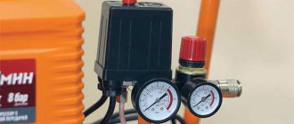
The pressure switch for the compressor is a unit containing the following elements.
- Terminals. Designed for connecting electrical cables to relays.
- Springs. Installed on adjusting screws. The pressure level in the receiver depends on the force of their compression.
- Membrane. It is installed under the spring and compresses it under the action of compressed air.
- Power button. Designed to start and force stop the unit.
- Connection flanges. Their number can be from 1 to 3. The flanges are designed for connecting the compressor start relay to the receiver, as well as for connecting a safety valve with a pressure gauge to them.
How to connect and configure a pressure switch?
In the general circuit diagram of a compressor installation, the pressure switch is located between the unloader valve and the secondary engine control circuit. Typically the pressure switch is equipped with four threaded heads. One of them is intended for connecting the device to the receiver, and the second is for connecting a control pressure gauge. One of the remaining connectors can be used to install a safety valve, and the remaining one can be fitted with a regular ¼-inch threaded plug. The presence of a free connector allows you to install the control pressure gauge in a place convenient for the user.
The pressure switch is connected in the following sequence:
- Connect the device to the unloading valve of the receiver.
- Install a control pressure gauge (if it is not necessary, then the threaded inlet is also plugged).
- Connect the terminals of the electric motor control circuit to the contacts (taking into account the selected connection diagram - to normally open or normally closed contacts). When the voltage in the network fluctuates, the connection is made not directly, but through a surge protector. This is also required when the power for which the contacts are designed exceeds the motor load current.
- If necessary, use the adjusting screws to adjust the relay to the required compressed air pressure values.
When connecting, you need to check whether the network voltage corresponds to the factory settings of the compressor pressure switch.
For example, in a three-phase network with a voltage of 380 V, the relay must have a three-contact group (two phases + zero), and for a voltage of 220 V - a two-contact group. The adjustment is made when the receiver is at least two-thirds full. To perform this operation, the relay is disconnected from the power supply, and, by removing the top cover, the compression of the two springs is changed. The adjusting screw, on which the axis of the larger diameter spring is mounted, is responsible for the upper limit of the working pressure. On the board next to it, the generally accepted pressure symbol (P - pressure) is usually indicated, and the direction of rotation of the screw by which this pressure is reduced or increased is also indicated. The second, smaller adjustment screw is responsible for setting the required pressure range (difference). It is marked with the symbol ΔР, and is also equipped with an indicator of the direction of rotation.
To reduce setup time, in some designs the adjusting screw for changing the upper pressure limit is moved outside the pressure switch housing. The result is monitored using the pressure gauge readings.
Diagrams for connecting the pressure switch to the compressor
The connection of the relay that controls the degree of air compression can be divided into 2 parts: the electrical connection of the relay to the unit and the connection of the relay to the compressor through the connecting flanges. Depending on which motor is installed in the compressor, 220 V or 380 V, there are different connection diagrams for the pressure switch. I am guided by these diagrams, provided that you have certain knowledge in electrical engineering, you can connect this relay with your own hands.
Connecting the relay to a 380 V network
To connect the automation to a compressor operating from a 380 V network, use a magnetic starter. Below is a diagram of connecting automation to three phases.
In the diagram, the circuit breaker is indicated by the letters “AB”, and the magnetic starter by “KM”. From this diagram it can be understood that the relay is set to a switch-on pressure of 3 atm. and shutdown - 10 atm.
Connecting the pressure switch to a 220 V network
The relay is connected to a single-phase network according to the diagrams given below.
These diagrams indicate various models of pressure switches of the RDK series, which can be connected in this way to the electrical part of the compressor.
Connecting the pressure switch to the unit
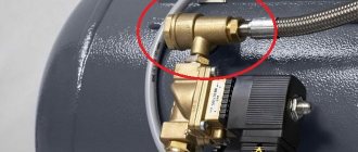
Connecting a pressure switch to a compressor is quite simple.
- Screw the pressure switch onto the receiver pipe using its central threaded hole. For better thread sealing, it is recommended to use fum tape or liquid sealant. The relay can also be connected to the receiver through a reducer.
- Connect a relief valve to the smallest output from the relay, if present.
- The remaining outputs from the relay can be connected to either a pressure gauge or a safety relief valve. The latter is installed without fail. If a pressure gauge is not required, then the free output of the pressure switch must be plugged with a metal plug.
- Next, wires from the electrical network and from the engine are connected to the sensor contacts.
After the complete connection of the pressure switch is completed, it is necessary to configure it for proper operation.
Installation of relays and auxiliary elements
In addition to basic components, devices are often equipped with additional devices that increase ease of use or expand the functionality of the device.
They are installed on flange connections, most often 1/4”
The pressure switch is connected to the compressor as follows:
- Screw the inlet pipe to the tank pipe.
- Connect a pressure gauge, unloading and safety valves to the flanges of the device.
- Close unused holes with plugs.
- Connect the electrical connector of the relay to the electric motor.
Low-power electric motors are connected directly; more powerful ones will require the use of a starter. The design of the pressure switch must match the engine power.