Information about the manufacturer of the horizontal tabletop milling machine NGF-110
The horizontal tabletop milling machine model NGF-110 is produced by the Rostov plant of small-sized machine tools MAGSO, KomTeh-Plus , founded in 1956.
ComTech Financial and Industrial Group , which has existed in the machine tool equipment market for several years and has priority in the production of small-sized metal-cutting machines: lathes, milling, vibrating, sharpening, drilling, which equip schools, vocational schools, colleges, institutes, repair and installation organizations of all regions of Russia.
Machines produced by the Rostov plant of small-sized machine tools MAGSO
- NS-16 - tabletop drilling machine Ø 16
- NGF-110Sh3 - low power milling machine 0.6 kW, table size 100x400 mm
- NGF-110Sh4 - low power milling machine 0.75 kW, table size 100x400 mm
- SNVSH - tabletop drilling machine Ø 16
- SNVSH-2 - tabletop drilling machine Ø 16
- TV-4
- educational screw-cutting lathe Ø 200, RMC 350 mm - TV-6
- educational screw-cutting lathe Ø 200, RMC 350 mm - TV-6M
- educational screw-cutting lathe Ø 200, RMC 350 mm Dubno - TV-7
- educational screw-cutting lathe Ø 220, RMC 330 mm - TV-7M - educational screw-cutting lathe Ø 220 mm, RMC 275 mm
- TV-9 - educational screw-cutting lathe Ø 220 mm, RMC 525 mm
- TV-11 - educational screw-cutting lathe with frequency converter Ø 240, RMC 750 mm
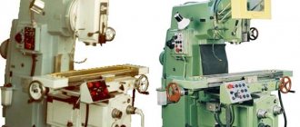
NGF-110Sh4 horizontal tabletop milling machine. Purpose and scope
The NGF-110Sh4 milling machine is produced according to TU-79 RSFSR 441-79 and replaced the outdated model of the NGF-110Sh3 milling machine, which was produced according to TU-79 RSFSR 355-72.
horizontal cantilever milling machine NGF-110 is designed to perform milling operations for processing horizontal planes, grooves and other surfaces. Installing a vertical milling head VFG allows you to additionally process vertical planes, as well as planes at a certain angle. Surface processing is carried out using disk, face, end, corner and shaped cutters.
The desktop horizontal milling machine model NGF-110Sh4 is special school equipment and is intended for industrial training in secondary schools for equipping school educational workshops.
Modifications of the desktop horizontal milling machine NGF-110
NGF-110sh1, NGF-110sh2 manufacturer: Plant No. 5 named after. Dzerzhinsky , city of Shchelkovo, Moscow region, village named after Sverdlov.
NGF-110sh2 manufacturer: Sapozhkovsky Mechanical Plant No. 7 , Sapozhok city, Ryazan region.
NGF-110sh3 0.6 kW, table size 100 x 400 mm manufacturer: Rostov plant MAGSO , founded in 1956.
NGF-110sh4 0.75 kW, table size 100 x 400 mm manufacturer: Rostov plant MAGSO , founded in 1956.
Designation of the milling machine NGF-110sh4. Letters and numbers mean:
- N - desktop machine;
- G - horizontal machine;
- F - milling machine;
- 110 — the largest diameter of the cutters used on the machine (mm);
- Ш - school;
- 1, 2, 3, 4 - machine model.
Features of modifications
The NGF-110 model was the first in a series of desktop school machines. It was modified and widely universal machines began to be produced.
NGF-110Sh1
Distinctive features of the model:
- round trunk;
- the vertical feed steering wheel is located at the base of the screw;
- The gear shift lever on the body is metal.
The bottom plate is cast, low, like the NGF-110 model.
NGF-110Sh3
Visually very different from previous models:
- a rectangular trunk with an arched top - “humpbacked”;
- the base is thin;
- engine start/stop buttons on the column, below;
- next to it is a plate with the model marking;
- plastic balls are screwed onto the ends of the gear shift knobs;
- engine inside the frame;
- vertical transmission is carried out by a handwheel on the console.
The model is considered transitional to the next modification.
110Ш4
The latest, modernized model, which was produced longer than the others. Differs from previous versions of the milling machine:
- a rectangular trunk with an earring moving along its guides;
- base high 100 mm, hollow;
- local lighting;
- Gear shift knobs are completely plastic;
- The label with the marking is located on the trunk.
On the side of the base there are power buttons, inside there is a current transformer for local lighting of 36 V. The motor is located at the bottom of the stand, inside.
NGF-110Sh4 Dimensions of the working space of the milling machine
Dimensions of the working space of the NGF-110sh4 milling machine
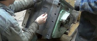
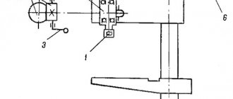
Sketch of a trunk with an earring of a horizontal milling machine NGF-110
- trunk
- earring
- screw
- earring sleeve
- screw
The stand in the upper part has dovetail-type guides in which trunk 1 is installed. The trunk can be moved along the guides manually. The trunk is clamped to the guides using a wedge, which, when the screw is tightened, is tightened and secures the trunk to the stand.
An earring 2 is installed at the front end of the trunk. The earring on the trunk is tightened with a nut 5. Rearranging the earring from one machine to another due to individual adjustment is not allowed.
The bronze bearing-sleeve of the earring 4 has a conical outer surface and two longitudinal cuts, due to which the clearance in the bearing is adjusted with a nut 3.
Before starting work, it is necessary to lubricate the inner cavity of the earring bushing with I-30A oil.
The gap adjustment is determined by the heating of the shackle bushing (when running for one hour at maximum spindle speed, the heating of the bushing should not exceed 50-60 ° C, with sufficient lubrication).
The mandrel is designed for fastening cylindrical disk and other cutters.
The cutters are mounted on the mandrel using mounting rings and a nut.
To ensure the rigidity of the cutting tool, the free end of the mandrel is installed in the support of the shackle. The earring is attached to the trunk.
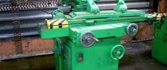
Reviews
The NGF-110 machines are over 50 years old, but DIY enthusiasts still use them. Reviews of the machine from their owners.
Yuri is 27 years old. The machine is awesome. My father put a vertical head on it, and even managed to mill door handles. He constantly sharpened chisels and straightened knives. Anton is 46 years old. Nice machine. Suitable for small workshops, garages. I do interesting things with it.
The NGF-110 machines, created for teaching children, are popular among tinkerers. They are easily restored and repaired thanks to a simple mechanism. The equipment is characterized by high purity of processing. Installing a vice and VFG increases the number of operations performed on the machines.
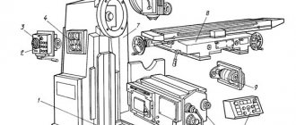
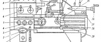
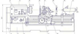
NGF-110 Location of components on the machine
Location of components on the NGF-110sh4 machine
List of components of a milling machine
- rack with gearbox
- console
- table with sled
- trunk with earring
- mandrel
- stove with electrical equipment
- protective screen
- vice
- local lighting lamp
NGF-110 Location of machine controls
Location of machine controls NGF-110
List of controls for the milling machine NGF-110
- handle, spindle speed switching
- handle, spindle speed switching
- longitudinal feed handwheel
- cross feed handwheel
- vertical feed handwheel
- push-button control station
Location of machine controls NGF-110
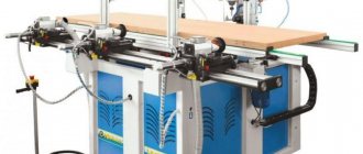
Analogs
To train teenagers in milling, a series of NGF-110 machines of various modifications were produced. Manufacturers are now offering multifunctional desktop milling equipment. These are mainly vertical milling machines and universal CNC equipment.
JET JUM-X2 is a highly versatile benchtop milling machine. Has vertical and horizontal spindles. The largest diameter of the disk cutter is 63 mm, the face cutter is 30 mm. Optimum MH50G is a tabletop machine with threading function. There is a head lift drive. The largest diameter of the end mill is 80 mm.
Important!
There is a large selection of desktop models on the milling machine market. They are mechanically driven in all gears, high-performance, multifunctional.
NGF-110 Kinematic diagram of a milling machine
Kinematic diagram of the NGF-110sh4 milling machine
Kinematic diagram of the NGF-110sh4 milling machine
Kinematic diagram of the NGF-110sh4 milling machine
Rotation from electric motor I is transmitted by a V-belt transmission to gearbox shaft II (Fig. 7). Next from shaft II. rotation is transmitted to shaft III and then to spindle IV through gears 4, 5, 6, fixedly mounted on shaft II, movable triple and double gear blocks sitting on shaft III and gears 12, 13 fixedly mounted on spindle IV.
Movable gear blocks allow six different spindle speeds to be achieved (see spindle speed graph).
Description of the main components of the NGF-110 milling machine
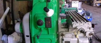
Machine stand NGF-110 with gearbox
The stand is the basic unit on which all other components and mechanisms of the machine are mounted.
The rigidity of the rack structure is achieved due to the developed base and the trapezoidal cross-section of the rack in height.
The rack is divided into two compartments. The gearbox is mounted in the upper compartment, and the electric motor is mounted in the lower compartment.
Gearbox of milling machine NGF-110
Photo of gearbox of milling machine NGF-110sh4
Diagram of the gearbox of the NGF-110sh4 milling machine
A three-shaft six-speed gearbox is mounted in the upper part of the rack housing and provides spindle speed control from 125 to 1250 rpm. The required rotation speed is selected using the switch levers located on the left side of the machine.
To inspect the gearbox, you must remove the side cover.
The spindle is a double-bearing hollow shaft. The short span between the supports and the significant diameter of the sections provide the necessary vibration resistance and rigidity of the spindle.
The front journal of the spindle is supported by two angular contact bearings 8 (Fig. 2), and the rear journal is supported by radial bearing 9. To eliminate the axial clearance of the front bearings, two nuts 10 are installed on the spindle. Spacer rings 11 and 12 are installed between the bearings. When the bearings wear out the gap in them is eliminated by grinding the ends of the internal spacer ring 12. The compensation ring 13 is used to eliminate the axial play of the spindle.
The main bearings that determine the geometric accuracy of the spindle are angular contact single row ball bearings No. 46 208 of the front support and radial ball bearing No. 206 of the rear support. In the axial direction, the spindle is fixed by the stand collar and the front cover.
The clearance in the front bearing is adjusted by tightening the nut located in the front part of the spindle.
To access this nut, it is recommended to remove the side cover on the rack.
Gearbox lubrication
Gear wheels and gearbox bearings are lubricated by splash lubrication.
I-30A oil is poured into the oil reservoir to a level controlled by the oil indicator.
Change the oil for the first time after 15 days of operation, then every 3 months.
The console is the basic unit of the feed mechanism. A table with a slide is installed on the console guides. Cross feed of the table is carried out from the cross feed screw 2. Vertical feed of the console along the guides of the rack is carried out from the vertical feed screw 3.
Milling machine work table and console
Table and console of the milling machine NGF-110sh4
Console of milling machine NGF-110sh4
Console of milling machine NGF-110sh4
The console is the basic unit of the feed mechanism. A table with a slide is installed on the console guides. Cross feed of the table is carried out from the cross feed screw 2. Vertical feed of the console along the guides of the rack is carried out from the vertical feed screw 3.
Work table of the milling machine NGF-110sh4
Milling machine table NGF-110sh4
- Table
- Sled
- Cross feed nut
- Longitudinal feed nut
- Longitudinal feed screw
- Table clamp screw on slide
The work table of the machine is the last element in the feed chain and has the ability to move in three directions: along the slide guides - longitudinally, together with the slide along the console guides - in the transverse direction, and together with the console along the rack guides - in the vertical direction.
Protective screen
A protective screen is installed on the machine to protect the worker from flying chips in the cutting zone.
Design Features
The NGF-110 machine is distinguished by its simple design. Some models have survived and continue to work in home workshops. The model does not have mechanical feeds; all work is done manually.
Console
The console is the basic unit of the feed mechanism. It moves horizontally. The helical clutch converts the rotation of the screw into linear motion. The movement handle is located at the bottom.
Table
The table has one longitudinal T-shaped groove on the working surface for fastening workpieces and a vice. In the longitudinal direction, the table moves along guides on the slide, and together with them moves along the console along the mandrel. The handwheels on the ends of the screws are located on the left side of the table and directly on the slide.
Rack
The conical stand is mounted on the machine plate. Inside, its cavity is divided horizontally into 2 parts. At the bottom there is an electrical cabinet. Above is the gearbox and spindle assembly. A round trunk is fixed above them.
On the top left of the case is the gear shift knob. On the left is a lever for clamping the trunk. There are guides in front along which the console moves vertically. The motor is mounted to the side or below the base under the table top. It is connected to the gearbox drive shaft pulley by a belt drive behind the rack.
Trunk with earring
The round trunk passes through the bushings at the top of the post. It moves along the axis manually and is fixed motionless by a wedge during operation. The trapezoidal-shaped earring has a hole equal in size to the diameter of the trunk and is clamped onto it with a nut. The mandrel is fixed in it in the same way. Free rotation is ensured by a bearing.
Protective screen
The glass, inserted into a metal frame, is moved into position manually and held by a lever stand. It is located on the left side of the body.
Important!
On the surviving NGF-110 machines, the protective screens are broken. Masters make new ones.
Special plate with equipment
Modernized machines, such as the widely universal NGF-110Sh4, have a high plate at the bottom. Its cavity contains electrical equipment, a push-button switching unit and a transformer. The rest have a screw attached to them to lift the console and a start button on the side.
Light source
Lighting is connected separately. The lampshade and lamp are attached with a long flexible stand to the side of the frame, above the electrical cabinet.
Mandrel
The mandrel is attached to the spindle cone, the free end is inserted into the shackle. To install the cutter in the desired position, spacer rings of various lengths and diameters are used. They are included in the tools kit.
A long key is inserted into the longitudinal groove, which allows you to fix the cutter and transmit rotational movement to it. A VFG is installed on the mandrel for drilling and milling the side surfaces.
Specifications
Part processing is carried out by moving the part mounted on the machine relative to the rotating tool.
Technical characteristics of the machine NGF-110:
- machine power 0.55 kW;
- spindle speed 125-1250 rpm;
- number of spindle speeds 6;
- table size 100×400 mm;
- number of T-slots 1;
- longitudinal movement of the table 250 mm;
- transverse – 85 mm;
- maximum cutter diameter 110 mm;
- maximum distance between the spindle axis and the table surface is 117 mm;
- machine dimensions 685×64×925 mm.
The displacement of the table by one division of the dial is equal to the transverse and longitudinal movement of 0.05 mm.
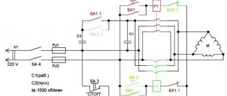
Electrical diagram of the milling machine NGF-110
Electrical diagram of the milling machine NGF-110sh4
Electrical equipment includes: a three-phase squirrel-cage asynchronous electric motor installed in the lower compartment of the rack, and a magnetic starter, transformer, terminal blocks, fuses, switches, push-button control station, thermal relay installed in insulated niches of the machine plate (item 6, Fig. 1).
The machine is equipped with a local lighting lamp
NGF-110sh3 General view of the universal milling machine
Photo of desktop milling machine NGF-110sh3
Photo of desktop milling machine NGF-110sh3
Photo of desktop milling machine NGF-110sh3
Photo of desktop milling machine NGF-110sh3
Technical characteristics of machine tools models NGF-110Sh4
| Parameter name | NGF-110sh3 | NGF-110sh4 |
| Basic machine parameters | ||
| Main dimensions GOST, TU | TU-79 RSFSR 355-72 | TU 79 RSFSR 441-79 |
| Accuracy class according to GOST 8-82 | N | N |
| Dimensions of the working surface of the table (length x width), mm | 100 x 400 | 100 x 400 |
| Distance from the axis of the horizontal spindle to the table, mm | 30..200 | 30..200 |
| Distance from the axis of the horizontal spindle to the trunk, mm | 85 | 85 |
| Distance from the end of the spindle to the suspension bearing (earring), mm | 235 | 235 |
| The largest diameter of the cutter installed on the machine, mm | 110 | 110 |
| Desktop | ||
| Maximum table longitudinal movement, mm | 250 | 250 |
| Maximum transverse movement of the table, mm | 85 | 85 |
| Maximum table movement vertical, mm | 170 | 170 |
| Number of T-slots | 1 | 1 |
| Movement of the table by one division of the longitudinal dial (one revolution), mm | 0,05 (4) | 0,05 (4) |
| Movement of the table by one division of the transverse dial (one revolution), mm | 0,05 (4) | 0,05 (4) |
| Movement of the table by one division of the vertical dial (one revolution), mm | 0,025 (2) | 0,025 (2) |
| Rapid table travel longitudinal/transverse/vertical, mm/min | No | No |
| Number of table feed stages | No | No |
| Limits of working mechanical table feeds. Longitudinal, transverse, vertical, mm/min | No | No |
| Table rotation angle (in the extreme forward position), degrees | No | No |
| Spindle | ||
| Horizontal spindle rotation speed, rpm | 100, 160, 250 ,490, 630, 1000 | 125, 200, 310, 500, 800, 1250 |
| Number of horizontal spindle speeds | 6 | 6 |
| Inner taper of horizontal spindle | Morse 3 | Morse 3 |
| Drive and electrical equipment | ||
| Number of electric motors on the machine | 1 | 1 |
| Main motion drive electric motor, kW (rpm) | 0,6 (1410..1440) | 0,55..0,75 (1390..1480) |
| Dimensions and weight of the machine | ||
| Machine dimensions (length x width x height), mm | 685 x 640 x 790 | 685 x 640 x 925 |
| Machine weight, kg | 200 | 340 |
- Tabletop horizontal milling machine NGF110Sh4. Operating manual, 1984
- TU 79 RSFSR 441-79
- Avrutin S.V. Fundamentals of Milling, 1962
- Avrutin S.V. Milling, 1963
- Acherkan N.S. Metal-cutting machines, Volume 1, 1965
- Barbashov F.A. Milling business 1973, p.141
- Barbashov F.A. Milling work (Vocational education), 1986
- Blumberg V.A. Milling machine handbook, 1984
- Grigoriev S.P. Practice of coordinate boring and milling work, 1980
- Kopylov R.B. Working on milling machines, 1971
- Kosovsky V.L. Handbook of a young milling operator, 1992, p. 180
- Kuvshinsky V.V. Milling, 1977
- Nichkov A.G. Milling machines (Machinist's Library), 1977
- Pikus M.Yu. A mechanic's guide to repairing metal-cutting machines, 1987
- Plotitsyn V.G. Calculations of settings and adjustments of milling machines, 1969
- Plotitsyn V.G. Setting up milling machines, 1975
- Ryabov S.A. Modern milling machines and their equipment, 2006
- Skhirtladze A.G., Novikov V.Yu. Technological equipment for machine-building industries, 1980
- Tepinkichiev V.K. Metal cutting machines, 1973
- Chernov N.N. Metal cutting machines, 1988
- Frenkel S.Sh. Handbook of a young milling operator (3rd ed.) (Vocational education), 1978
Bibliography:
Related Links. Additional Information
- Milling machines: general information, classification, designation
- School lathes. Review
- Comparative characteristics of cantilever milling machines of the 6N, 6M, 6R, 6T
- Feed box for console milling machines of the 6M : 6M12P, 6M13P, 6M82, 6M83, 6M82Sh, 6M83Sh
- Feed box for console milling machines of the 6P : 6P12, 6P13, 6P82, 6P83, 6P82Sh, 6P83Sh
- Feed box for console milling machines 6T : 6T12, 6T13, 6T82, 6T83, 6T82Sh, 6T83Sh
- Milling machine repair technology
- Adjustment of milling machines
- Friction clutch. Friction shaft. Friction clutches in metal-cutting machines
- Automatic cycles of milling machines (6P12)
- Testing and checking metal-cutting machines for accuracy
- Directory of universal milling machines
- Manufacturers of metal-cutting machines in Russia
- Manufacturers of milling machines in Russia
Home About the company News Articles Price list Contacts Reference information Interesting video KPO woodworking machines Manufacturers