Gas flame spraying in
The result of this flame spraying process is the formation of a stable continuous spray, which is achieved through a strict sequence of actions: heating, melting, dispersing the resulting mixture, transferring molten particles of the acetylene-acid flame of the material to the metal surface of the part.
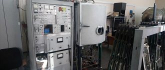
The flame spraying process uses a torch based on acetylene oxygen or propane oxygen. A substance is transferred into its flame from the feeder (for example, wire - FS15 installation), it melts and, with the help of compressed air, enters the surface of the part. The heated mixture, cooling, forms a durable coating on the part.
This method of operation can be used either manually or using special equipment.
Using flame spraying, it is possible to apply coatings from the following alloys: iron, nickel, copper, aluminum, zinc.
Application of flame spraying:
- restoration of equipment functionality;
- strengthening the strength of new parts;
- production of shut-off valves (75% of all ball valves manufactured abroad);
- to restore the geometry of parts of pumping and compressor equipment, covers and shafts of electric motors;
- restoration of babbitt coating of bearings;
- creation of anti-corrosion coatings;
- Rilsan coatings (insulating coatings for pipeline systems);
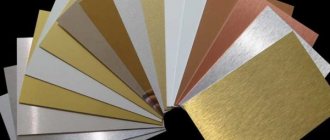
- decorative coverings of objects exposed to adverse external environmental influences (bas-reliefs, monuments, fountains, etc.)
Depending on what you want to create a coating for, different requirements are imposed on it, i.e. its composition, thickness, density, and adhesion density to the surface of the substrate change.
Subsequently, after hardening, the created coating can be processed by grinding or cutting. This processing method is explained by porosity in 2-10% of all coatings created using flame spraying.
Advantages of flame spraying:
- can be used on objects of any size (pipelines, ships, bridges, turbine blades, etc.);
- you can set the required porosity of the coating (up to 30%) and its thickness;
- wood, glass, metals, various types of plastics, and composite materials are used as a substrate;
- when spraying is carried out, the coated part is not deformed (since it does not require strong heating);
- You can apply any materials that have a melting point or softening range;
- Spraying is allowed under normal weather conditions, in water, in a special room with a controlled inert atmosphere;
- coating is carried out with metals, alloys, carbides, nitrides, borides, plastics and combinations of materials with a melting point from 300°C to 3500°C;
- a reduction in the cost of the final object is achieved, because for its initial coating (before processing), it is permissible to use less expensive materials;
- more efficient use of materials and energy resources;
- increasing the durability of products and their service life;
- the influence of phenomena such as corrosion and erosion on parts is minimized;
- relatively small time costs to create the coating;
- low noise level during operation;
- low background radiation;
- the ability to configure the work process in offline mode;
- the equipment does not require complex care and maintenance;
- The equipment itself is mobile and it is possible to carry out the spraying process directly on site, without dismantling parts.
Disadvantages of technology:
- when testing the adhesion strength of the created spraying to the surface of a part for normal breakthrough, sometimes unacceptable results are achieved (5–45 MPa);
- without additional treatment, it is prohibited to use products with such a coating in corrosive environments due to high porosity (5-25%);
- it is impossible to apply a coating from materials whose melting point is above 2800 °C;
- low coefficient of energy use of the gas-flame flow for heating the powder (2–12%).
High temperature coatings
1.1. High temperature coating materials
The operational reliability of machines is limited by the service life of parts operating under extreme conditions, i.e. at elevated temperatures, pressures and speeds.
Such parts are nozzle blades of gas turbine engines, elements of the piston group of internal combustion engines, etc. The service life of such parts can be significantly increased by applying heat-resistant coatings that protect the surface from high-temperature oxidation, erosion, and softening of the base material. The materials for high-temperature coatings are oxides and solid compounds: carbides, borides, nitrides, silicides.
Refractory oxides . Alpha aluminum oxide (α-Al2O3) is characterized by high mechanical strength, has several modifications, and has a melting point of 2050 °C.
In nature, aluminum oxide occurs in the form of corundum, sapphire or ruby.
Beryllium oxide (BeO) is a stable, slightly volatile compound with a melting point of 2570 °C. Its melting point is higher than that of aluminum oxide, and its mechanical strength is slightly lower than that of aluminum oxide. Due to its high electrical resistance, low electrical losses and low density, it is a better insulator than aluminum oxide, especially at high temperatures (1700-2000 ° C).
Cerium oxide exists in two forms: Ce2O2 and CeO2. The latter is more stable and melts at a temperature of 2593-2737 °C. Although cerium oxide is considered a rare earth material, it is practically more common in the earth's crust than zinc or tin.
Hafnium oxide HfO2 is commonly present in zirconium-containing minerals (2-7%); As a rule, hafnium oxide is not separated from zirconium oxide. Since the melting point of HfO2 is 2810 °C and it forms a solid solution with zirconium oxide (ZrO2), its presence does not deteriorate the properties of ZrO2. Pure hafnium oxide is a rare and expensive material.
Nickel oxide (NiO) is an easily reduced oxide. Its melting point is 1949 °C. Nickel oxide is the only refractory material that can be reduced to a metallic state in a hydrogen atmosphere. The volumetric changes accompanying this reaction are so great that they cause destruction of NiO products.
Thorium oxide (ThO2) is the most refractory, characterized by a melting point of 3200 °C. The limitations of its use are determined by its high density, high cost, and weak resistance to thermal shock.
Titanium oxide (TiO2) is a chemically stable crystalline substance that melts at 1840 °C. It is valued as a dielectric.
Solid compounds - carbides, nitrides, borides and silicides have similar structures, since the nitrogen and carbon atoms are in interstitial positions in the metal lattice. These materials have low electrical resistance; Moreover, most carbides, borides, and nitrides are distinguished by high thermal conductivity and great hardness.
Carbides are the most refractory substances: 4 TaС* ZrC (tmelt=3918 °C), 4 TaС*HfC (tmelt=3928 °С). Silicon carbide (SiC) and boron carbide (BC) are known as abrasives, and titanium carbide (TiC) and tungsten (WC) are known as components of hard alloys.
Nitrides are similar in properties to carbides, but their tendency to oxidize is greater than that of carbides. The most stable nitrides are HfN and ZrN. These materials can be successfully used for work in vacuum up to a temperature of 1800°C. When in contact with carbon, nitrides interact with it, forming carbides; Usually this reaction occurs even in a nitrogen atmosphere.
Borides are stable in the temperature range 2000-3200 °C. As a rule, all borides are characterized by low volatility, low electrical resistance, high hardness and good thermal conductivity. Borides are one of the few materials that are sufficiently stable and slightly volatile at 2500°C, and therefore can be effective heat-resistant materials.
Boron silicides B6Si and B4Si are suitable for use at high temperatures and are stable for a long time, at 1400 °C. They have high resistance to thermal shock. When oxidized, they form a protective body of borosilicate glass.
The developed heat-resistant and heat-protective coatings are divided into three groups (Fig. 1):
- single-layer metal type CrAlYZr HfSi (Fig. 1 a);
- two-layer coatings with internal metal CrAlYZrHfSi and external ceramic ZrO2 - Y2O3 (Fig. 1 b);
- three-layer coatings with internal metal CrAlYZrHfS, intermediate metal CrAlY; external ceramic ZrO2 - Y2O3 (Fig. 1c).
a B C
Figure 1 - Schemes of heat-resistant and heat-protective coatings: a - single-layer, b - two-layer, c - three-layer
The total thickness of single-layer coatings does not exceed 150 microns, two-layer - 200 microns and three-layer - 300 microns. The thickness of the inner layer in three-layer coatings ranges from 30 to 50 microns, intermediate 50-80 microns, external 80-120 microns. The concentration of chromium, aluminum, sodium, zirconium, hafnium, silicon in the heat-resistant layer is respectively 18-24% wt, 10-130% wt, 0.4-1.8 wt, zirconium, hafnium, silicon from 0.05 to 0. 2% wt.
Additional alloying of CrAlY alloys with zirconium, hafnium, and silicon made it possible: on the one hand, to increase the heat resistance of single-layer multicomponent and composite heat-resistant coatings, and on the other hand, to slow down diffusion processes at the boundaries of the base - damping inner layer - outer ceramic layer - and thereby increase the service life of the coating generally.
An even more significant slowdown of diffusion processes in the layers that make up the coating is observed when the intermediate heat-resistant layer is made in the microlayer version from 0.5 to 1 μm. In this case, optimal characteristics are achieved at a concentration of dispersed refractory particles (ZrO2 - Y2O3, Al2O3) in the microlayer from 0.3 to 1% wt.
1.2. Technological basis of thermal spraying processes
Depending on the heat source, the following methods of gas-thermal coating are distinguished:
- flame spraying,
- plasma,
- electric arc metallization,
- detonation-gas,
- vacuum condensation spraying.
The essence of gas-thermal coating processes is the formation of a directed flow of dispersed particles of the sprayed material and their transfer to the surface of the workpiece at temperatures and speeds that are optimal for the formation of a coating layer.
A general diagram of the thermal spraying process is presented in Figure 2.
Figure 2 - Scheme of the thermal spraying process: 1 - nozzle part of the particle generator; 2 - three-phase jet (Ι - condensed particles, ΙΙ - atoms of atomizing gas, ΙΙΙ - vapor phase); 3 - coating; 4—spray surface; Φ is the divergence angle of the particle flow; dпн — diameter of the spray spot
The sprayed material in the form of a powder, wire or rod will enter the heating zone and disperse. A distinction is made between radial and axial material feed. The heated particles are sprayed with gas. The main purpose of the gas is to accelerate particles in the axial direction. Atomizing gas, when using wires or rods, can disperse the molten material.
The coating is formed from powder particles that are in a molten state with partial melting, unmelted and partially solidified. When spraying wires and rods, the coating is formed from molten particles with a wide range of dispersion.
A number of requirements are imposed on the flow of sprayed particles to ensure favorable conditions for coating formation:
- the heating temperature of the particles must be sufficient to form strong adhesive bonds with the spraying surface. At low particle velocities (50-500 m/s), the heating temperature should be higher than the melting point of the material. High particle velocities (800-1000 m/s) make it possible to form coatings at temperatures up to 0.9 the melting point of the particle material;
- the speed of particles in the flow is determined depending on their temperature. It should be 50-100 m/s (minimum for molten superheated particles, maximum for unmelted particles in a viscoplastic state);
- The flow divergence angle φ should be 5-20 º. The minimum divergence angle ensures compact particle flows and the possibility of forming coatings.
The most important parameters of the sprayed material: physical and chemical properties, size of powder particles, diameter of the rod and wire.
Use wire with a diameter of 0.5-5 mm. The wire feed speed is selected as maximum for the given operating mode (2-10 mm/s).
The parameters characterizing the external conditions of spraying are: ambient pressure; spraying distance; spraying angle; temperature of the product, its shape and size; speed of movement of the spray spot.
1.3. Gas flame spraying
A gas flame is produced by the combustion of combustible gases in oxygen or air. The following flammable gases are used for spraying coatings: acetylene (C3H3), methane (CH4), propane (C3H8), butane (C4H10), hydrogen (H2), etc. The physicochemical properties of combustible gases are presented in Table 1.
Table 1 - Physico-chemical properties of flammable gases
| Flammable gas | Relative density in air | Calorific value at 25 ºС and 0.1 MPa, MJ/m³ | Heat of release during neutral combustion, MJ/m³ | Flame propagation speed in a mixture with oxygen, m/s | Temperature of gas flame mixed with oxygen, °K |
| Acetylene | 0,91 | 56,5 | 18,5 | 13,5 | 3100-3200 |
| Methane | 0,56 | 35 | 1,4 | 3,3 | 2000-2100 |
| Propane | 1,57 | 93,5 | 12,6 | 3,7 | 2400-2700 |
| Butane | 2,1 | 125,1 | – | – | 2400-2700 |
| Hydrogen | 0,07 | 10,8 | – | 8,9 | 2000-2100 |
Powder, flexible cords in a polymer sheath filled with powders, as well as flux-cored wires in a metal sheath are used as the sprayed material in flame spraying. The sprayed material is fed along the axis of the gas-flame jet into the torch (Fig. 3).
Figure 3 - Schematic diagram of gas-flame spraying: 1 - nozzle, 2 - gas torch; 3 - coating; 4 - substrate
The technological parameters that have the greatest impact on the efficiency of the process include: the diameter of the gas nozzle, the diameter of the holes on the periphery of the nozzle, the angle of inclination of the axis of the holes to the axis of the atomizer.
The transport gas pressure is selected within the range of 0.1-0.2 MPa, gas flow 0.3-0.6 m³/h, supply speed 180-500 m/h, mass of consumable material 5-30 kg/h.
The spraying distance is 100-200 mm, the speed of movement of the spray spot is 0.2-0.3 m/s. With powder spraying, the temperature of the sprayed material does not exceed 2200 ºС, with wire spraying - 2700 ºС.
Sprayers are being created that provide acceleration of gas-flame flows to supersonic and even hypersonic speeds. Fine powders are used as the material. This can provide coatings with low porosity (2-3%), with small pores (less than 10 microns), and roughness Rz 25...30.
The disadvantages of the flame spraying method include: the presence in the jet of active gases that interact with the sprayed materials; low values of effective heating efficiency of powder particles (1..15%); low quality coatings made from powder materials.
1.4. Electric arc metallization
The process is carried out by melting the coating material with an electric arc while simultaneously spraying it with gas. The most widely used two-electrode scheme (Fig. 4).
Figure 4 - Scheme of the two-electrode electric arc metallization process: 1 - electric arc; 2 — electrodes; 3 - nozzle; 4 — feed mechanism; 5 - contact devices; 6 - sprayed mixture
The sprayed material in the form of electrode wire 2 with a diameter of 1.0-5.0 mm is supplied by the feed mechanism 4 to the arc combustion zone 1. Voltage from the power source is supplied to the contact devices 5. Between the crossing electrodes there is a nozzle 3, designed to create a high-speed atomizing gas flow . For these purposes, compressed gas is used: nitrogen, argon, etc. The gas jet tears off the molten metal from the ends of the wires, disperses it and forms a stream of deposited particles together with the atomizing gas.
Along with two-electrode ones, three-electrode metallization schemes are also used. The electrode wires are placed along the generatrices of a truncated cone at an angle of 120º and use alternating three-phase current.
The shape and size of the nozzle have the greatest influence on the spraying process. Typically, cylindrical nozzles with a diameter of 3-6 mm are used.
Electric arc metallization is widely used in the formation of corrosion-resistant coatings of various building structures. A coating of aluminum and zinc is formed. Steel, bronze, etc. are used as wear-resistant coatings.
The advantages of the method are: high energy efficiency atomization, reaching 70-90%; high productivity up to 50 kg/h; the possibility of obtaining high-quality coatings with high adhesive strength and low porosity.
The disadvantages of the method are: interaction of particles with the active gas phase and saturation of the sprayed metal with oxygen and nitrogen; limited application of the method only to electrically conductive materials.
1.5. Vacuum condensation spraying of coatings
The coating during vacuum condensation deposition is formed by a flow of particles that are in an atomic, molecular or ionized state. The flow of particles is obtained by spraying the material in various ways: thermal evaporation of the material from a solid or molten state; explosive evaporation and melting; ion sputtering of solid material.
The process of vacuum condensation spraying is usually considered to consist of three stages: the transition of the condensed phase (solid or liquid) to gaseous (steam); flow formation and particle transfer to the condensation surface; vapor condensation on the spray surface and coating formation.
The process is carried out in rigid sealed chambers at a pressure of 13.3-13.3·10-3 Pa (Fig. 5). The highest vapor pressure, reaching 13.3 Pa or more, is observed near the evaporation surface. This causes the particles to move towards the surface of the product, where the vapor pressure is minimal.
Figure 5 - Scheme of the vacuum condensation deposition process: 1 - screen; 2 — working gas supercharger; 3 - coating; 4 - sprayed product; 5 - damper; 6 — flow of sprayed particles; 7 — supply of atomization energy; 8 — sprayed material; 9 - vacuum chamber; 10 - base plate
The introduction of active gases into the chamber makes it possible to switch to the method of vacuum reaction coating. Particles in the flow or on the condensation surface enter into chemical interaction with active gases (oxygen, nitrogen, etc.) and form the corresponding compounds: oxides, nitrides, etc.
Thermal evaporation of a material occurs when it is heated above its melting point. For most materials these temperatures exceed 1000-2000 ºС. The material is heated in an evaporator, the purpose of which is to hold the molten material until a vacuum of 1-100 Pa is achieved and ensure minimal heat losses. For example, the use of ceramic crucibles reduces the power of the heat source compared to water-cooled copper crucibles by 4-6 times. At the same time, copper crucibles allow materials to be evaporated without changing their composition. The use of several crucibles simultaneously makes it possible to obtain coatings with complex compositions and high uniformity in thickness.
1.6. Detonation gas coatings
Detonation-gas coating involves the use of specific sources of heating, atomization and acceleration of sprayed particles.
Figure 6 - Scheme of the spraying process: 1 - ignition chamber, 2 - igniter; 3 - shock waves; 4 - detonation wave; 5 - camera; 6 - flammable mixture; 7 — muzzle flame; 8 - flow of sprayed particles
A specified amount of a gas mixture, for example, C2H2 + O2 + N2, is supplied to the ignition chamber 1. Using a powerful electric discharge, the mixture is ignited through igniter 2. The flame spreads through the volume of gases with increasing speed. Shock wave 3 appears. Combustion turns into detonation. From this moment, a detonation wave 4 propagates along the barrel of chamber 5, representing a complex of a shock wave and a chemical reaction.
In the shock wave, the gas is compressed to a pressure of several tens of atmospheres, and the temperature rises to several thousand degrees and becomes significantly higher than the critical temperature at which the mixture reacts.
After the detonation wave reaches the open end of the barrel, the detonation wave is destroyed and a muzzle flame 7 is formed. The detonation products begin to flow out of the barrel in the form of a supersonic jet. The temperature and pressure of detonation products in the barrel decreases.
When expiring, the detonation products entrain the sprayed particles. A two-phase flow is formed, consisting of detonation products and sprayed particles. The two-phase flow is heterogeneous both along the length and cross-section of the barrel. Detonation products heat and accelerate the sprayed particles. After the two-phase flow leaves the barrel, the products of detonation coatings expand sharply. Their temperature, speed and density decrease with distance from the trunk. Near the surface of the workpiece, the gas flow slows down and then spreads along the obstacle.
When spraying materials of a homogeneous chemical composition, the coating can be formed from almost completely melted particles and from a mixture of molten and unmelted materials.
The cycle time consists of three components: the time required to fill the barrel chamber with the gas mixture; the time of explosion and release of detonation products and powders and the time of purging the chamber and barrel. Typically, the time of one cycle is 0.2-0.5 s. During one cycle, 30-40 mg of sprayed material is transferred to the surface. With one cycle, a single spot with a diameter of 20-30 mm and a thickness of 10-30 microns is formed.
There are single-barrel and multi-barrel installations, the latter providing increased productivity. The barrel diameter (8-40 mm) and its length 1200-2000 mm have a great influence on the efficiency of the process.
The advantages of detonation gas spraying are:
- high quality coating;
- increase in fatigue strength due to cold hardening;
- moderate heating of products during their spraying (t<300ºC);
- fairly high productivity (1-10 kg/h);
- wide range of sprayed materials;
- low sensitivity to the condition of the initial spraying surface (heating, contamination, roughness);
- unlimited size and shape of products. For example, both large products (up to 10 m long, 2-3 m in diameter, weighing up to 4 tons) and small ones (surgical instruments, drills, taps, etc.) are subjected to spraying.
The disadvantages should be noted:
- difficulty in applying coatings to products with a large surface and high hardness (HRC>60);
- difficulty in spraying coatings from low-density powders (titanium carbides, etc.);
- impossibility of spraying internal surfaces to a depth exceeding the diameter of the inlet;
- high noise level (140 dB and above);
- the need to use sealed boxes and remote control of the process;
- quite high cost of equipment.
1.6.1. Application of detonation coatings
The scope of application of detonation coatings is very wide. The range of parts with detonation coatings is constantly expanding. The detonation coating method, initially tested and successfully mastered in the aviation and space industries, has found wide application in other industries.
A significant argument in favor of the use of detonation coatings is the possibility of obtaining structures with low weight combined with high wear resistance. The effect is enhanced by the fact that the technological process of detonation coating practically does not change the original configuration of the part and does not have a noticeable effect on the microstructure of the material due to local thermal effects. The part itself rarely heats up to temperatures above 200ºС. If necessary, the temperature of the part is reduced by blowing it with carbon dioxide or air. Thanks to this, it is possible to coat parts manufactured with high precision and maintain it.
Some surfaces of parts made of low-melting materials (for example, the inner surface of an aluminum alloy bushing with a diameter of about 10 mm) can only be properly coated using the detonation method, since other gas-thermal methods require the parts to be located in an intense heating zone.
Detonation coatings are most widely used in the field of increasing the service life of turbine blades of aircraft engines, compressors, etc.
Detonation coatings facilitate the introduction of lighter alloys into aircraft engine structures and components. For example, a coating based on tungsten carbide has made it possible to successfully use titanium blades in turbojet engines. The use of levers made of aluminum alloys with wear surfaces coated with hard alloys made it possible to reduce the overall weight of the aircraft.
In mechanical engineering, the main task of using detonation coatings is to reduce the wear of rubbing mating parts for various purposes. Increasing speed, thermal and power loads require the materials of moving machine parts to combine very contradictory properties: low mass and high strength, heat resistance and heat resistance, wear resistance, low friction coefficient, etc.
Experience in using detonation coatings based on aluminum oxide has shown that they have high wear resistance over a wide range of loads and friction rates in combination with various materials. Comparative tests of sliding bearings, the working surface of which was covered with a wear-resistant coating and operating in a corrosive environment, showed a 30-fold increase in service life.
The use of detonation coatings for tools allows us to solve the problem of an optimal combination of rigidity and wear resistance. Possessing high hardness and adhesion strength to the base, applied coatings made of hard alloy and aluminum oxide will allow you to obtain high-quality edges on cutting tools for various purposes.
Thus, the service life of cutting blades used for cutting plastics, rubber, paper and coated with a layer of hard alloy based on tungsten carbide with a thickness of 0.05 mm increases from 3 to 12 times.
Detonation hard alloy coatings applied to the surface of carbon steel inserts used as saw teeth when cutting cardboard, asbestos fabric and similar materials increase service life by 50 times.
Detonation coatings on fiberglass cutting knives increase their service life by 10 to 20 times.
Ultrasonic-assisted tungsten carbide-coated tubular drill bits last 50 times longer than conventional tools.
When drawing wire through dies coated with chromium oxide, the resistance increased by 3-7 times.
Punches with detonation coatings have 10 to 20 times longer service life than chrome-plated steel ones.
Stages of work
Stage 1. Surface preparation.
The surface preparation stage includes the following operations:
- degreasing the surface of the product using hydrocarbon solvents in the presence of oil and fat inclusions.
- washing areas of the product to remove salts, atmospheric contaminants, coking;
- abrasive blasting, waterjet or hydrodynamic surface cleaning to remove old coating, rust, scale and roughen it;
- surface drying (using waterjet or hydrodynamic cleaning technologies)
- manual cleaning and rounding of sharp corners, edges, removal of burrs and cooking splashes.
- blowing with compressed air and removing dust from the surface.
Quality control of the prepared surface is carried out for compliance with the following criteria:
- abrasive blasting cleaning must be carried out to the degree determined by the regulations (SPR), as a rule, this is the degree SA 2-2.5 - 3 according to ISO 8501 and checked visually by comparison with the standard;
- manual cleaning must be carried out to degree St 2-2.5-3 according to ISO 8501 and checked visually by comparison with a standard;
- roughness Rz µm (depending on PPR conditions) - checked using a comparator or profilometer according to ISO 8503-1
- degree of dust removal according to ISO 8502-3 - checked by the number and size of dust particles;
- the degree of degreasing is checked using a luminescent method according to GOST 12.2.052-81.
Stage 2. Gas flame spraying
During gas plasma spraying, droplets (microparticles) of molten metal are formed, which are then transferred to the surface being treated, creating a continuous metal coating on it. The filler material is supplied to the burner flame, melts, and is sprayed with compressed air over the surface to be treated. After cooling, a fairly durable coating is formed on the surface of the workpiece.
The flame coating process can be performed with simultaneous reflow, but this is only possible when using a gas flame. Due to the strong, but not uniform heating of the sprayed layer, the plasma jet cannot ensure that a high-quality coating is obtained as a result of the work. Stages of spraying with simultaneous reflow:
- heating the entire surface to be treated to a temperature of 250-300 °C;
- to prevent oxidation, it is recommended to apply a protective layer 0.2-0.3 mm thick to the areas being restored;
- heat the sprayed surface area until it “fogs”;
- Spray a new layer onto the previously melted layer and bring it to the melting state.
During the melting process, it is important to prevent overheating of the sprayed layer to the state of a liquid bath, and after completion of the technological process, it is necessary to ensure smooth cooling of the surface of the part. This is easily achieved by using sand and asbestos. Violation of this technological process will lead to increased porosity of the layer, dripping of the metal in case of overheating, the appearance of cracks, peeling in case of uneven cooling.
Stage 3. Quality control.
Quality control of flame spraying by appearance is carried out by inspecting products for the presence of mechanical damage such as chips, swelling, peeling, cracks, cavities. In this case, an external examination is carried out using a tenfold magnifying glass.
Measurements of spray thickness should be made in accessible places where there are no knurls or surface defects that are 5 mm or more from the edges of units, edges, contact points and holes.
Necessary:
- inspect the appearance of the spraying with the naked eye to identify cracks, pores, and peelings. These defects detected in this way are not acceptable in the coating;
- measure the coating hardness of the restored surface at three or more points. The actual value of the coating hardness should be considered the average value of the measurements obtained. The use of instruments that perform ultrasonic measurements for these purposes is unacceptable. This is primarily due to the porosity (albeit insignificant) of flame spraying.
Development of gas-flame processing of metals
Welding or cutting metal is not the entire range of applications for processing metals with a gas flame. Scientists are constantly developing this industry and introducing into production gas-flame machines and devices made using the latest advanced technologies. They are distinguished by high performance and low energy consumption. In addition, the latest models were created by scientists who are concerned about the state of the environment. Therefore, harmful emissions into the atmosphere from such equipment are minimized.
Safety precautions when working with gas-flame processing of metals
All equipment for such metal processing must be painted in a special color. Which one depends on the gas itself. White color indicates the presence of acetylene, red indicates flammable gas, gray is for liquid gas. There should also be warning signs indicating the name of the gas and the word “dangerous.” The tank for liquid fuel must be sealed, have a certain pressure and strength.
The basic safety rule is the impossibility of allowing untrained or unauthorized people to access gas-flame equipment. The availability of protective clothing is also an important safety issue.
In such production, the issue of safety is always related to the issue of fire safety, since improper handling of gas will inevitably cause an explosion and fire. Therefore, the worker should always pay special attention to the strength of the hoses and not allow gas to pass through at the connection points.