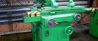
Universal milling machines with a wide profile are very beneficial for a wide variety of large enterprises. The 6T13 unit is a vertical milling equipment that allows you to process straight, corner, and frame parts.
The machine can perform processing on a horizontal, vertical surface, as well as at an angle of 45°, and not only, more details about all the capabilities of the unit.
Information about the manufacturer of the 6T13 cantilever milling machine
The manufacturer of the 6T13 series of universal milling machines is the Gorky Milling Machine Plant , founded in 1931.
The plant specializes in the production of a wide range of universal milling machines, as well as milling machines with DRO and CNC, and is one of the most famous machine-tool enterprises in Russia.
Since 1932, the Gorky Milling Machine Plant has been producing machine tools and is an expert in the development and production of various metal-cutting equipment.
Universal milling machines of the T series have been produced by the Gorky Milling Machine Plant (GZFS) since 1985. The machines are similar in design, widely unified and are a further improvement of similar machines of the P series (6P12, 6P13).
Today the 6T13 cantilever milling machine produces:
- Stanochny Park LLC;
- LLC SO "PRESSMASH";
- Machine tool association LLC SO "StanRos".
Products of the Gorky Milling Machine Plant GZFS
- 6G605
double-spindle longitudinal milling machine, 500 x 1600 - 6M12P
vertical cantilever milling machine, 320 x 1250 - 6M13P
vertical cantilever milling machine, 400 x 1600 - 6M82
universal horizontal milling machine, 320 x 1250 - 6M82G
horizontal cantilever milling machine, 320 x 1250 - 6М82Ш
universal cantilever milling machine, 320 x 1250 - 6M83
universal horizontal milling machine, 400 x 1600 - 6M83G
horizontal cantilever milling machine, 400 x 1600 - 6М83Ш
horizontal cantilever milling machine, 400 x 1600 - 6N12
vertical cantilever milling machine, 320 x 1250 - 6N13P
vertical cantilever milling machine, 400 x 1600 - 6N82
horizontal cantilever milling machine, 320 x 1250 - 6N82G
horizontal cantilever milling machine, 320 x 1250 - 6Р12, 6Р12Б
vertical cantilever milling machine, 320 x 1250 - 6Р13, 6Р13Б
vertical cantilever milling machine, 400 x 1600 - 6Р13Ф3
vertical cantilever milling machine with CNC, 400 x 1600 - 6Р82
universal horizontal milling machine, 320 x 1250 - 6R82G
horizontal cantilever milling machine, 320 x 1250 - 6Р82Ш
universal cantilever milling machine, 320 x 1250 - 6Р83
universal horizontal milling machine, 400 x 1600 - 6R83G
horizontal cantilever milling machine, 400 x 1600 - 6Р83Ш
universal cantilever milling machine, 400 x 1600 - 6T12-1
vertical cantilever milling machine, 320 x 1250 - 6T12
vertical console-milling machine, vertical, 320 x 1250 - 6T12F20
vertical cantilever milling machine with CNC, 320 x 1250 - 6T13
vertical cantilever milling machine, 400 x 1600 - 6T13F20
vertical cantilever milling machine with CNC, 400 x 1600 - 6T13F3
vertical cantilever milling machine with CNC, 400 x 1600 - 6T82
universal horizontal milling machine, 320 x 1250 - 6T82-1
universal horizontal milling machine, 320 x 1250 - 6T82G
horizontal cantilever milling machine, 320 x 1250 - 6Т82Ш
universal cantilever milling machine, 320 x 1250 - 6T83
universal horizontal milling machine, 400 x 1600 - 6T83-1
universal horizontal milling machine, 400 x 1600 - 6T83G
universal horizontal milling machine, 400 x 1600 - 6Т83Ш
universal cantilever milling machine, 400 x 1600 - 6605
double-spindle longitudinal milling machine, 500 x 1600 - 6606
three-spindle longitudinal milling machine, 630 x 2000 - GF2171
vertical milling machine with CNC and ASI, 400 x 1600
Exploitation
To increase operating efficiency, each machine is equipped with a set of auxiliary circuits - bearings, slings, lubrication, kinematics, and so on. The rest of the manual includes electrical equipment. Here is a schematic diagram for connecting electrical appliances, as well as a set of specifications for selecting spare parts.
Based on statistical data obtained during the long-term production of the machine, the manufacturer has compiled a list of wearing parts. For them, a separate drawing of each element is provided. Thanks to unification, it becomes possible to use spare parts from other series of 6T machines, including 6T13.
6T13 vertical cantilever milling machine. Purpose and scope
The vertical cantilever milling machine 6T13 is designed on the basis of the basic model 6T13-1
with a high degree of unification of functional units and parts.
6T13 vertical cantilever milling machine is designed for milling all kinds of parts from various materials. It is used in single and serial production.
The 6T13 cantilever milling machine differs from the 6T12 machine in the installed power of the main movement and feed motors, the dimensions of the working surface of the table and the amount of table movement.
6T13 machine can process vertical and horizontal planes, grooves, corners, frames, gears, etc.
The vertical console milling machine 6T13 can operate in three modes:
- Automatic - In automatic mode, the machine operates at various automatic cycles.
- Jog — In jog mode, adjustment movements of the table are made. Marking work is possible.
- Manual - In the manual universal mode, the machine operates using working feeds, rapid movements, as well as manual movements from the flywheels and handle.
Design features of the 6T13 milling machine
The technological capabilities of machines can be expanded through the use of overhead milling, dividing and slotting heads, and a round rotary table.
There is a device for limiting the gap in the screw pair for the longitudinal movement of the table, individual lubrication of the vertical movement screw, which increases its durability and reduces the lifting force of the console.
Additional devices have been introduced to protect against flying chips and emulsions .
The rigidity of the machine has been increased due to the rectangular guides of the bed and console.
There is automatic spindle braking in operating mode and during emergency shutdown.
Automated lubrication of components increases their durability and reduces maintenance time.
The machine table can be rotated around a vertical axis by ±45° , which makes it possible to mill various helical spirals using dividing devices.
The rotating spindle head of the machine is equipped with a mechanism for manual axial movement of the spindle sleeve, which allows processing of holes whose axis is located at an angle of up to ±45° to the working surface of the table.
The drive power and high rigidity of the machines allow the use of cutters made of high-speed steel, as well as tools equipped with plates made of hard and super-hard synthetic materials.
Tool fastening is mechanized . The cross-feed screw is located along the axis of the cutter, which increases processing accuracy. The technological capabilities of the machine can be expanded with the use of a dividing head, a rotary round table and other devices.
The ability to configure the machine for various semi-automatic and automatic cycles allows you to organize multi-machine maintenance and use the machine to perform various jobs in continuous production.
6T13 machine can be supplied to countries with temperate, cold and tropical climates.
Machine accuracy class - N according to GOST 8-82E
The main design advantages of the machines:
- mechanized tool fastening in the spindle;
- proportional feed deceleration mechanism;
- a device for periodically adjusting the size of the gap in the longitudinal feed screw pair;
- safety clutch protecting the feed drive from overloads;
- braking of the horizontal spindle when stopping using an electromagnetic clutch;
- protection device against flying chips.
Main technological advantages of the machines:
- various automatic machine operation cycles;
- wide range of spindle speeds and table feeds;
- high drive power;
- high rigidity;
- reliability and durability.
- The technological capabilities of machine tools can be expanded by using a dividing head, a round rotary table and other devices.
The machines are produced in various versions according to voltage and frequency of the supply network. Spare parts are supplied.
Modifications of console-milling machines of the “T” series
Various modifications and specialized machines have been developed based on the “T” series machines:
- 6T12 - 6T12-27, 6T12-29, 6T12-30
- 6Т13 - 6Т13-27, 6Т13-29, 6Т13-30
- 6T82G - 6T82G-27 (GF2793), 6T82G-29, 6T82G-30
- 6T83G - 6T83G-27 (GF2797), 6T83G-29, 6T83G-30
- 6T82 - 6T82-27 (GF2794), 6T82-29, 6T82-30
- 6T83 - 6T83-27 (GF2798), 6T83-29, 6T83-30
- 6T82Sh - 6T82Sh-27, 6T82Sh-29, 6T82Sh-30, 6T82Sh-35, 6T82Sh-36, 6T82Sh-37, 6T82Sh-38
- 6T83Sh - 6T83Sh-27, 6T83Sh-29, 6T83Sh-30, 6T83Sh-35, 6T83Sh-36, 6T83Sh-37, 6T83Sh-38
Modifications 6T...-27 have a 100 mm increased distance from the spindle axis (end) to the working surface of the table and a mechanism for proportional (2 times) slowdown of the working feed.
Russian and foreign analogues of the 6T12 (6T13) machine
FSS350MR, FSS450MR - 315 x 1250, 400 x 1250 - manufacturer Gomel Machine-Tool Plant
VM127M - (400 x 1600) - manufacturer Votkinsk Machine-Building Plant GPO, Federal State Unitary Enterprise
6D12, 6K12 - 320 x 1250 - manufacturer Dmitrov milling machine plant DZFS
X5032, X5040 - 320 x 1320 - manufacturer Shandong Weida Heavy Industries, China
FV321M, (FV401) - 320 x 1350 (400 x 1600) - manufacturer Arsenal JSCo. — Kazanlak, Arsenal AD, Bulgaria
History of production of machine tools by the Gorky plant, GZFS
In 1937
, the first cantilever milling machines of the 6B series, models 6B12 and 6B82 , with a work table of 320 x 1250 mm (2nd standard size)
at
the Gorky Milling Machine Plant In 1951
6N of cantilever milling machines was put into production 6N13PR machine received the “Grand Prix” at the world exhibition in Brussels in 1956.
In 1960
6M cantilever milling machines
was launched into production In 1972
6P of cantilever milling machines
was launched into production In 1975
year, copying cantilever-milling machines were launched into production:
6Р13К .
In 1978
In 2009, copying cantilever-milling machines
6Р12К-1 , 6Р82К-1 .
In 1985
6T-1 of cantilever milling machines
was put into production In 1991
6T of cantilever milling machines was put into production
General information
In the mid-80s, Gorky mastered the production of new brands of milling machines: 6T12, 6T13, representing the development of the R generation. The purpose and scope of application remained the same: milling of all kinds of parts mainly from ferrous metals and alloys in workshops with the type of production from single to medium-series.
Explanation of the name of the machine according to ENIMS encoding:
- 6- milling (group);
- T- modification (series);
- 1- vertical (subgroup);
- 3- standard size (version);
- normal accuracy (class H is not indicated in the designation).
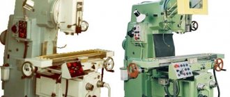
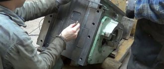
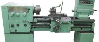
General view of the vertical cantilever milling machine 6T13
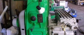
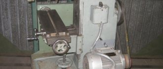
Photo of the 6T13 cantilever milling machine
Photo of the 6T13 cantilever milling machine
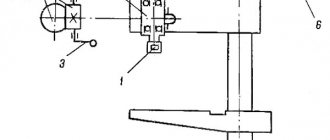
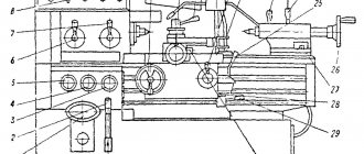
Arrangement of components of the 6T13 cantilever milling machine
Location of components of the 6T13 milling machine
List of components of the 6T13 cantilever milling machine
- bed
- side remote control
- feed switch mechanism
- spindle gearbox
- rotating head
- electromechanical tool clamping devices
- control cabinet
- table and sled
- feed delay mechanism
- main remote control
- console
- gearbox
Safety precautions when working with the device
The machine is an object of increased danger. Therefore, when working with it, certain rules should be followed. Beginners must undergo safety training.
When working, the operator must wear special clothing. It is prohibited to approach the machine while intoxicated. Before work, you should check the grounding. It is also prohibited to switch speeds and modes while the head is rotating. The control cabinet door and access to the electric drives are locked with a key.
Location of controls for the 6T13 cantilever milling machine
Location of controls for the 6T12 milling machine
Control panels for milling machine 6T13
Control panels for milling machine 6T13: main -II, side -I
List of controls for the 6T13 cantilever milling machine
- Spindle speed indicator
- Button “Move table back, forward, down”
- Switch for selecting the direction of table movement
- Switch “Clamp-Release Tool”
- Button “Move table forward, left, up”
- Spindle Jog button (duplicate)
- Button “Stop table movement”
- Spindle start button
- “Spindle Stop” button (duplicate)
- Emergency Stop button
- Button “Fast table movement” (duplicate)
- Spindle speed shift knob
- —
- Hexagon head rotation
- Spindle sleeve clamp handle
- Key "Move table left"
- "Move table to the right" key
- Key "Stop longitudinal movement of the table"
- Spindle Stop button
- Spindle start button
- Table Clamps
- Switch for switching on the table operating mode “Manual - Mechanical”
- Flywheel for manual longitudinal movement of the table
- Vernier ring
- Limb of the table transverse movement mechanism
- Manual lateral movement of the table
- Manual vertical table movement
- Feed switch mushroom
- Emergency Stop button
- Machine operating mode selection switch
- Slow feed switch
- Button “Fast table movement and cycle start”
- “Stop vertical table movement” key
- "Move table down" key
- Slide Clamps
- "Move table up" key
- Flywheel for manual longitudinal movement of the table (duplicate)
- Key "Stop lateral movement of the table"
- "Move table forward" key
- "Move table back" key
- Spindle sleeve extension flywheel
- Clamping the head on the frame
- Input switch
- Spindle rotation direction switch “Left - Right”
- Cooling pump switch "On - Off"
- Control panel selection switch
- Auto cycle selection switch
- Console Clamp
- Removable handle for manual vertical and transverse movement of the table
- Zero head fixation pin
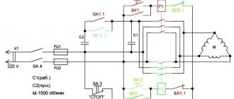
Kinematic diagram of the 6T13 cantilever milling machine
Kinematic diagram of the 6T13 cantilever milling machine
The kinematic diagram is given to understand the connections and interactions of the main elements of the machine. The numbers of teeth (g) of the gears are indicated on the callouts (the asterisk indicates the number of starts of the worm).
The main movement is driven by a flange electric motor through an elastic coupling.
The spindle speed is changed by moving three toothed blocks along the splined shafts.
The gearbox provides the spindle with 18 different speeds.
The feed drive is carried out from a flange electric motor mounted in the console. By means of two three-crown blocks and a movable gear wheel with a cam clutch, the feed box provides 18 different feeds, which are transmitted through a ball safety clutch to the console and then, when the corresponding cam clutch is engaged, to the screws of longitudinal, transverse and vertical movements.
Accelerated movements are obtained when the high-speed clutch is turned on, the rotation of which is carried out through intermediate gears directly from the feed electric motor.
The clutch is interlocked with the working feed clutch, which eliminates the possibility of their simultaneous activation.
Graphs explaining the structure of the machine feed mechanism are shown in Fig. 6 and 7. For machines of models 6T13B (Fig. 7) vertical feeds are 3 times less than longitudinal ones.
Design of the main components of the 6T13 cantilever milling machine
bed
The bed is the base unit on which the remaining components and mechanisms of the machine are mounted.
The frame is rigidly fixed to the base and fixed with pins.
Rotating head of the 6T13 cantilever milling machine
The rotating head (Fig.) is centered in the annular recess of the bed neck and is attached to it with four bolts that fit into a single groove in the bed flange.
The spindle is a two-support shaft mounted in a retractable sleeve. The axial play in the spindle is adjusted by grinding rings 3 and 4. Increased play in the front bearing is eliminated by grinding half rings 5 and tightening the nut.
The adjustment is carried out in the following order:
- the spindle sleeve extends;
- flange 6 is dismantled;
- half rings are removed;
- a screw plug is removed from the right side of the head body;
- through the hole, unscrewing screw 2 unlocks nut 1;
- Nut 1 is locked with a steel rod. By turning the spindle by the nut, the nut is tightened and this moves the inner race of the bearing. After checking the play in the bearing, the spindle is run in at maximum speed. When operating for an hour, the heating of the bearings should not exceed 60° C;
- the size of the gap between the bearing and the spindle collar is measured, after which the half rings 5 are ground to the required amount;
- the half rings are put in place and secured;
- Flange 6 is screwed in.
To eliminate radial play of 0.01 mm, the half rings must be ground by approximately 0.12 mm.
Rotation is transmitted to the spindle from the gearbox through a pair of bevel and a pair of cylindrical gears mounted in the head.
The bearings and gears of the rotary head are lubricated from the frame pump, and the spindle bearings and the sleeve moving mechanism are lubricated by extrusion.
Gearbox
The gearbox is mounted directly in the frame body. The connection of the box to the electric motor shaft is carried out by an elastic coupling, which allows misalignment in the motor installation of up to 0.5-0.7 mm.
The gearbox can be inspected through the window on the right side.
The gearbox is lubricated by a plunger pump (Fig. 9), driven by an eccentric. Pump capacity is about 2 l/min. Oil is supplied to the pump through a filter. From the pump, the oil flows to the oil distributor, from which it is discharged through a copper tube to the pump control eye and through a flexible hose to the rotary head. The gearbox elements are lubricated by splashing oil coming from the holes in the oil distributor tube located above the gearbox.
Gearbox
The gearbox allows you to select the required speed without sequentially passing through intermediate stages.
Rack 19 (Fig. 10), moved by shift handle 18, through sector 15 through fork 22 (Fig. 11) moves the main roller 29 with shift disc 21 in the axial direction.
The shift disk can be turned by the speed indicator 23 through the bevel gears 28 and 30. The disk has several rows of holes of a certain size located against the pins of the racks 31 and 33.
The racks engage in pairs with gear 32. A shift fork is attached to one of each pair of racks. When moving the disk by pressing on the pin of one of the pair, reciprocating movement of the slats is ensured.
In this case, the forks at the end of the disk stroke occupy a position corresponding to the engagement of certain pairs of gears. To eliminate the possibility of hard stop of the gears when switching, the pins of 20 racks are spring-loaded.
Fixation of the dial when choosing a speed is ensured by ball 27, which slides into the groove of sprocket 24.
The spring 25 is adjusted by the plug 26, taking into account the clear fixation of the dial and the normal force when turning it.
Handle 18 (see Fig. 10) is held in the on position by spring 17 and ball 16. In this case, the handle tenon fits into the groove of the flange.
Correspondence of speeds to the values indicated on the indicator is achieved by a certain position of the bevel wheels along the mesh. Correct engagement is established by cores at the ends of the mating tooth and cavity or by setting the pointer to the speed position of 31.5 rpm and the disk with forks to the speed position of 31.5 rpm (for machine models 6Т13Б the corresponding speed is 50 rpm) . The gap in the engagement of the conical pair should not be more than 0.2 mm, since the disk can rotate up to 1 mm due to this.
The gearbox is lubricated from the gearbox lubrication system by splashing oil.
How does the rotating head of the machine work?
The image above shows the current drawing of the rotary head, which is used in the 6T12 machine. It is centered in the annular recess located in the neck of the frame, secured with 4 bolts that fit into 1 different groove of the frame flange.
The spindle consists of a double-bearing shaft, which is integrated into the sliding sleeve. Adjusting the axial play comes down to the need to grind rings 4 and 3. Elimination of increased play in the front bearing becomes possible by tightening the nut and grinding ring 5. The owner is required to follow the correct maintenance procedure. To get rid of the radial play, the value of which is one hundredth of a millimeter, a grinding of approximately 0.12 millimeters is required.
The spindle rotates through a pair of cylindrical and conical wheels that are installed in the head. The gears and bearings installed in the turning head are lubricated by a pump in the frame. Bearings responsible for the correct operation of the sleeve movement mechanism and spindle rotation - using the injection method.
Technical characteristics of the cantilever milling machine 6T13
| Parameter name | 6Р12 | 6Р13 | 6T12 | 6T13 |
| Basic machine parameters | ||||
| Table surface dimensions, mm | 1250 x 320 | 1600 x 400 | 1250 x 320 | 1600 x 400 |
| Maximum mass of the workpiece, kg | 250 | 300 | 400 | 630 |
| Maximum longitudinal stroke of the table (X), mm | 800 | 1000 | 800 | 1000 |
| Maximum transverse travel of the table (Y), mm | 250 | 300 | 320 | 400 |
| Maximum vertical travel of the table (Z), mm | 420 | 420 | 420 | 430 |
| Distance from the end of the spindle to the table surface, mm | 30..450 | 30..500 | 30..450 | 70..500 |
| Distance from the spindle axis to the vertical guides of the bed (overhang), mm | 350 | 420 | 380 | 460 |
| Spindle | ||||
| Main drive drive power, kW | 7,5 | 10 | 7,5 | 11 |
| Spindle speed, rpm | 40..2000 | 40..2000 | 31,5..1600 | 31,5..1600 |
| Number of spindle speeds | 18 | 18 | 18 | 18 |
| Spindle quill movement, mm | 70 | 80 | 70 | 80 |
| Movement of the spindle quill by one dial division, mm | 0,05 | 0,05 | 0,05 | 0,05 |
| Spindle head rotation angle, degrees | ±45° | ±45° | ±45° | ±45° |
| Spindle end GOST 836-62 | №3 | №3 | ||
| Spindle end GOST 24644-81, row 4, version 6 | 50 | 50 | ||
| Desktop. Submissions | ||||
| Limits of longitudinal and transverse table feeds (X, Y), mm/min | 12,5..1600 | 12,5..1600 | 12,5..1600 | 12,5..1600 |
| Limits of vertical table feeds (Z), mm/min | 4,1..530 | 4,1..530 | 4,1..530 | 4,1..530 |
| Number of table feeds (longitudinal, transverse, vertical) | 22 | 22 | 22 | 22 |
| Speed of fast movements (longitudinal, transverse/vertical) X, Y/ Z, m/min | 4/ 1,330 | 4/ 1,330 | 4/ 1,330 | 4/ 1,330 |
| Movement of the table by one dial division (longitudinal, transverse, vertical), mm | 0,05 | 0,05 | 0,05 | 0,05 |
| Table movement per one revolution of the dial (longitudinal, transverse/vertical), mm | 6/ 2 | 6/ 2 | 6/ 2 | 6/ 2 |
| Maximum permissible cutting force (longitudinal/transverse/vertical), kN | 15/ 12/ 5 | 20/ 12/ 8 | ||
| Machine mechanics | ||||
| Feed stops (longitudinal, transverse, vertical) | Eat | Eat | Eat | Eat |
| Blocking manual and mechanical feeds (longitudinal, transverse, vertical) | Eat | Eat | Eat | Eat |
| Blocking separate feed switching | Eat | Eat | Eat | Eat |
| Spindle braking | Eat | Eat | Eat | Eat |
| Overload safety clutch | Eat | Eat | Eat | Eat |
| Automatic intermittent feed | Eat | Eat | Eat | Eat |
| Electrical equipment and machine drives | ||||
| Number of electric motors on the machine | 4 | 4 | 4 | 4 |
| Main motion electric motor, kW | 7,5 | 10 | 7,5 | 11 |
| Feed drive electric motor, kW | 2,2 | 3 | 3 | 3 |
| Tool clamping motor, kW | 0,25 | 0,25 | ||
| Coolant pump electric motor, kW | 0,125 | 0,125 | 0,12 | 0,12 |
| Total power of all electric motors, kW | 10,87 | 14,37 | ||
| Dimensions and weight of the machine | ||||
| Machine dimensions (length width height), mm | 2305 1950 2020 | 2560 2260 2120 | 2280 1965 2265 | 2570 2252 2430 |
| Machine weight, kg | 3120 | 4200 | 3250 | 4300 |
- Vertical cantilever milling machines 6T12-1, 6T13-1. Operating manual 6T12-1.00.000 RE,
- Vertical console-milling machines 6T12, 6T13. Operating manual 6T12.00.000 RE,
- Vertical cantilever milling machines 6T12-29, 6T13-29. Operating manual 6T12-29.00.000 RE, 1992
- Cantilever milling machines 6T82G-1, 6T82-1, 6T12-1, 6T82SH-1, 6T83G-1, 6T83-1, 6T13-1, 6T83SH-1. Operating manual for electrical equipment 6T82G.00.000 RE1
- Avrutin S.V. Fundamentals of Milling, 1962
- Avrutin S.V. Milling, 1963
- Acherkan N.S. Metal-cutting machines, Volume 1, 1965
- Barbashov F.A. Milling 1973
- Barbashov F.A. Milling work (Vocational education), 1986
- Blumberg V.A. Milling machine handbook, 1984
- Grigoriev S.P. Practice of coordinate boring and milling work, 1980
- Kopylov Work on milling machines, 1971
- Kosovsky V.L. Handbook of a young milling operator, 1992
- Kuvshinsky V.V. Milling, 1977
- Nichkov A.G. Milling machines (Machinist's Library), 1977
- Pikus M.Yu. A mechanic's guide to repairing metal-cutting machines, 1987
- Plotitsyn V.G. Calculations of settings and adjustments of milling machines, 1969
- Plotitsyn V.G. Setting up milling machines, 1975
- Ryabov S.A. Modern milling machines and their equipment, 2006
- Skhirtladze A.G., Novikov V.Yu. Technological equipment for machine-building industries, 1980
- Tepinkichiev V.K. Metal cutting machines, 1973
- Chernov N.N. Metal cutting machines, 1988
- Frenkel S.Sh. Handbook of a young milling operator (3rd ed.) (Vocational education), 1978
Bibliography:
Related Links. Additional Information
- Milling machines: general information, classification, designation
- Comparative characteristics of cantilever milling machines of the 6N, 6M, 6R, 6T
- Feed box for console milling machines of the 6M : 6M12P, 6M13P, 6M82, 6M83, 6M82Sh, 6M83Sh
- Feed box for console milling machines of the 6P : 6P12, 6P13, 6P82, 6P83, 6P82Sh, 6P83Sh
- Feed box for console milling machines 6T : 6T12, 6T13, 6T82, 6T83, 6T82Sh, 6T83Sh
- Milling machine repair technology
- Adjustment of milling machines
- Friction clutch. Friction shaft. Friction clutches in metal-cutting machines
- Automatic cycles of milling machines (6P12)
- Testing and checking metal-cutting machines for accuracy
- Directory of universal milling machines
- Manufacturers of metal-cutting machines in Russia
- Manufacturers of milling machines in Russia
- Electrical equipment of milling machines 6T12, 6T13, 6T82, 6T82G, 6T82Sh, 6T83, 6T83G, 6T83Sh
- Electrical equipment of milling machines 6P12, 6P13, 6Р82, 6Р82Г, 6Р82Ш, 6Р83, 6Р83Г, 6Р83Ш, 6Р12Б, 6Р13Б
- Electrical equipment of milling machines 6M12P, 6M12PB, 6M13P, 6M13PB, 6M82, 6M82Sh, 6M82GB, 6M83, 6M83Sh
- Electrical equipment of milling machines 6T10, 6T80, 6T80G, 6T80Sh
- Electrical equipment of milling machines 6Р10, 6Р80, 6Р80Г, 6Р80Ш
- Electrical equipment of milling machines 6N10, 6N80, 6N80G, 6N80Sh
Electrical equipment of milling machines of the Gorky Machine Tool Plant, GZFS
Electrical equipment of milling machines of the Vilnius Zalgiris Machine Tool Plant
All equipment - Customize slogan
The unit is produced by one of the largest machine-tool enterprises in our country - the Gorky Plant, which is recognized as a real expert in the field of design and manufacture of such equipment. The machine belongs to the “T” series, which replaced the “P” series units in the mid-1980s.
Milling units of this group have a number of technological advantages:
- durability and operational reliability;
- the presence of several automatic operating programs;
- the possibility of increasing the technological potential of equipment through the use of a rotary round table and dividing head;
- increased rigidity;
- high drive power;
- large selection of table feed frequencies and spindle rotation.
Structurally, the machine is also characterized by many successful solutions that increase the efficiency of using milling equipment.
It installs:
- a device that protects the operator from chips formed during the processing of workpieces;
- fastening a mechanized type of working device in the spindle;
- a protective clutch that protects the feed drive from overloads;
- a mechanism for regulating (performed periodically) the gap indicator in the screw pair;
- device for slowing down (according to a proportional scheme) the feed.
The unit makes it possible to work with gears, angles, horizontal and vertical planes, various frames and grooves in three modes:
- push;
- emergency;
- manual.
With a jog operating pattern, the machine can operate according to pre-applied markings and carry out specified movements of the work table. In automatic mode, several cycles are provided, including on the frame. Manual mode is considered universal. In this case, the milling installation is controlled by the operator using handles and flywheels, which can be used to set rapid movements and working feeds.
The rigidity of the unit is high, ensured by the presence of console guides and a rectangular frame. And the reliability of the machine is due to the lubrication of the vertical screw, the use of which reduces the force of movement of the console, which increases the durability of the milling unit.
Other advantages of the machine that are highly valued by experts usually include the following:
- reduction of regular maintenance time due to the use of an automatic lubricating device that processes all components of the unit;
- equipping the spindle head (rotary) with a device for axial movement in manual mode (it allows you to work with holes with an axis placed at an angle of ±45° to the table surface);
- The milling tool is fastened mechanically;
- the ability to rotate ±45° around the vertical axis of the work table (this allows you to process helical spirals, subject to the use of additional devices);
- the rigidity of the unit and the high power of its drives makes it possible to install tools made of high-speed steels, cutters made of tool steels and with synthetic super-hard cutting inserts;
- excellent precision in machining parts, which is determined by the location of the transverse screw along the axis of the working tool.
The main characteristics of the unit are as follows:
- maximum workpiece weight for processing – 630 kg;
- machine dimensions: 2570 mm – length, 2430 mm – height, 2252 mm – width;
- table parameters for milling – 400x1600 mm;
- weight of the assembled unit – 4300 kg;
- mechanics: presence of intermittent automatic feed, spindle braking system, blocking of mechanical and manual feed, switching stops, fuse clutch;
- vertical feeds (limit values): vertical – 4.1–530 mm/min, longitudinal and transverse – 12.5–1600 mm/min;
- maximum table travel: vertical – 430 mm, transverse – 400 mm, longitudinal – 1000 mm.