Equipment operating conditions
Devices of models of horizontal milling machines 6Р81Г, 6Р81 are currently not produced by manufacturers.
Instead, more modernized models are being created. Each of the modern units is equipped with an electronic control unit. This allows you to reduce the human factor, which consists of defects in the manufacture of parts, and increase the accuracy class. However, these devices can still be seen in use for individual purposes. An internship of two months allows a person to quickly learn how to operate the unit.
The lubrication system in this unit must always function normally. If for some reason it stops flowing into the special outlet for this, it is recommended to disconnect the unit from the power supply. And check the pumps and feed mechanisms. The machine has two centralized oil supply systems. The first is in the spindle drive, the second is in the feed mechanism.
If the feed on the milling machine suddenly does not turn on, first of all check the presence of oil in the gearbox. In the second case, the blocking may work. The feed may not work if the motor is not rotated correctly.
Repair of milling machine 6Р81
Oil filters should also be cleaned periodically. This will allow the machine to function without complaints for many years.
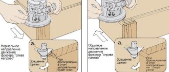
Timely preventative maintenance will allow you to use this device for a long time without the need for repairs.
If you find an error, please select a piece of text and press Ctrl+Enter.
Also useful for repairs:
- Cable aabl 3x120 technical specifications
- Canned food under a fur coat recipe
- Speed controller for an electric motor from a washing machine - diagram
Operating conditions of the 6р81г machine and types of work performed
All machines of the 6Р81, 6Н81, 6Р81Г, 6М81 series have been discontinued from line production today. They were replaced by more modernized units with an electronic control unit. These machines continue to be used mainly for individual and small-scale production. Operating the machine does not require any special training; it is enough to complete a two-month internship.
The horizontal milling machine 6р81 successfully carries out work on processing materials with various cutters in a limited workshop area. The speed of changing end, corner, end and other cutting surfaces allows the machine to be used for all automatic and semi-automatic production lines.
Electrical diagram of milling machine 6Р81
Electrical diagram of horizontal milling machine 6р81
Electrical equipment of milling machines of the Gorky Machine Tool Plant, GZFS
Electrical equipment of milling machines 6T12, 6T13, 6T82, 6T82G, 6T82Sh, 6T83, 6T83G, 6T83Sh
Electrical equipment of milling machines
6P12, 6P13, 6Р82, 6Р82Г, 6Р82Ш, 6Р83, 6Р83Г, 6Р83Ш, 6Р12Б, 6Р13Б
Electrical equipment of milling machines 6М12П, 6М12ПБ, 6М13П, 6М13ПБ, 6М82, 6M82Sh, 6M82GB, 6M83, 6M83Sh
Electrical equipment of milling machines of the Vilnius Zalgiris Machine Tool Plant
Electrical equipment of milling machines 6T10, 6T80, 6T80G, 6T80Sh
Electrical equipment of milling machines 6Р10, 6Р80, 6Р80Г, 6Р80Ш
Electrical equipment of milling machines 6N10, 6N80, 6N80G, 6N80Sh
Electrical equipment of milling machines of the Dmitrov Machine Tool Plant, DZFS
Electrical equipment of milling machines 6Р11, 6Р81, 6Р81Г, 6Р81Ш
Electrical equipment of milling machines 6N11, 6N81, 6N81G, 6N81A
Arrangement of components of the horizontal cantilever milling machine 6R81G
Arrangement of components of the 6р81г cantilever milling machine
Components of the horizontal cantilever milling machine 6R81G
- Bed - 6Р81Г-11.001
- Earring – 6Р81Г-11.000
- Spindle drive - 6Р81Г-21.01
- Gearbox - 6Р81Г-31.02
- Gearbox switching - 6Р81Г-33.01
- Feed box - 6N81G-51.02A
- Gearbox - 6N81G-52.01
- Reverse box - 6N81G-53.01A
- Feed switching - 6N81G-55.02
- Console - 6N81G-60.05
- Table - 6N81G-70.01A
- Table and console lubrication system - 6N81G-83.02
- Cooling system - 6Р81Г-84.01
- Electrical cabinet - 6Р81Г-95.02А
- Electrical equipment - 6Р81Г-99.05А
- Accessories - 6Р81Г.ОП
Models, descriptions, characteristics and types of machines
There is a wide variety of models and types of machines; in this catalog we will try to collect the most popular of them, both on the domestic market and abroad, and write the most complete, detailed characteristics and descriptions of the machines. Add as much technical information as possible, as well as technical documentation for these machines. If you have interesting descriptions of machines or passports for them and you want to share them with everyone, send the material by email, it will definitely appear on the pages of the portal.
We do not post materials with a copyright icon or a prohibition on copying, this is prohibited by law!
Design features
Let's look at the features in more detail.
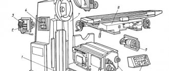
Location and purpose of components
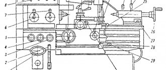
Cast frame 1 combines the remaining components. It is divided into two cavities: the upper one, partially filled with oil, with gearbox 7, spindle drive 5, and the base, where the cooling system is located. The slider 24 with the lug 3 moves along horizontal guides made on top of the frame. On the left are the gear shift mechanism 8 and the electrical cabinet 19.
The console 13 rests on a vertical screw attached through a glass to the base and on the frame guides. It moves along them manually, mechanically at working or accelerated feed. Gearbox housings 10, feed boxes 9, bolted together into a single unit, are installed inside the console. The mating wheels 47, 49 (see Fig. 5.) connect the gearbox to the reverse box 11.
The rotation transmitted by the gearbox is distributed by the reverse box through the safety clutch to the screws of the longitudinal and transverse stroke of the table 14; vertical – console.
Rice. 3. Location of main components
Location of controls
Steering wheels, handles, switches, control buttons are grouped by purpose and placed at a convenient height near the controlled mechanisms. Station 18 combines buttons: spindle start, feed; general stop. Nearby are the handles for switching the search 2 and speeds 4. When setting up, the trunk is moved by rotating the square 1. Mounted on the electrical cabinet door are: the “spindle push” button 5, the cooling pump switch 6, the rotation reverse switch 7. The input circuit breaker 8 is installed on the side wall.
Mechanical longitudinal, transverse, and vertical feeds are activated by handles 10, 12, 13, respectively. The mechanics of selecting the feeds is activated by the lever 17. The feeds are switched by a fixed handle 16. Manual longitudinal and transverse movements are made by rotating the flywheels 22, 14, respectively. To raise and lower the console with the table, use a removable curved handle 15. Accelerated movement in any direction turns on the lever 21.
Screws 11 secure the slide against rotation. Levers 24, 25 secure the table against longitudinal and transverse movements (the console clamp is not shown). The slider is immobilized by square 19. Stops 3 disable table lifting, stops 9 – transverse movement (similar longitudinal ones 23). Local lighting is switched with toggle switch 20, the manual lubricating pump is pumped with handle 26.
Fig.4. Controls
Kinematic diagram
Spindle chain
Shaft V imparts rotation to the spindle directly through a claw coupling or through two gear pairs: 16/18, 19/17. The choice is made by a selector handle connected to the fork, clutch half-clutch or 19/17 wheels. A V-belt drive connects shaft V to the output shaft of box IV. Combinations of options for pairing double-crown blocks placed on shafts I and III provide 16 rotation speeds
Feed chain
The transmission of motion from the feed motor to the table is clear from the kinematic diagram. Let's consider the separation of the working and accelerated movement chains. Through an intermediate gear 39/40, worm 42 mounted on shaft XII, gear 33 rotates worm wheel 43 mounted on shaft XIII on bearings. The wheel is jammed by overrunning clutches 131, as a result of which a kinematic, force closure occurs, and the table is given a working feed.
At accelerated speeds, movement is transmitted to the XIII shaft by gear 23/44. The wheel 44 assembled on bearings rotates the shaft only when the friction clutch 132 is engaged, causing the clutch 131 to operate and the wheel 43 to disengage.
Fig.5. The scheme is kinematic.
Repair cost
- Depending on the degree of damage, general condition, size, weight, year of manufacture, the cost varies. The minimum cost is 7,000 rubles, the average is around 30,000 rubles (for most machines from the 80s, for this amount you can completely update part of the equipment.
- A separate type of repair is surface restoration. Corrosion and oxidation processes do not relate to mechanism failures, but directly affect the performance of the process, since corrosion will sooner or later spread to the entire surface of the machine and disrupt its integrity, and the contact of materials with the table forms an oxide film, which impairs the adhesion and quality of the final product. Materials experts typically charge between $40 and $200 per job.
- Network switching is also a special column in repair costs. When replacing an engine with an imported one, a drop in the entire network may occur, since American electronic devices are designed for a different voltage. When replacing one machine in the workshop, you need to make sure that it is correctly connected to the general network by measuring the input and output voltage and running the installation in test mode, and then connecting all the others. The work of an electrical installation team can cost $80-300, depending on the number of machines in the workshop and the area of the enterprise.
It’s better to play it safe and perform a full range of diagnostic work, because it will be a shame if rust or a power outage renders the newly purchased equipment unusable.
6N81A Widely universal cantilever milling machine. Purpose and scope
The widely-universal cantilever milling machine 6N81A with a rotating milling head is designed for processing small products made of steel, cast iron, non-ferrous metals and plastics with cylindrical, end, disk, angular and special cutters.
Operating principle and design features of the machine
The spindle of the 6N81A machine can be rotated in a vertical plane by 115° and occupy horizontal, vertical and inclined positions.
If there is a dividing head on the 6N81A machine, it is possible to process gears with straight and spiral teeth, spiral drills, and similar products.
The main dimensions of the machine correspond to GOST 165-49, accuracy standards correspond to GOST 154-41, GOST-155-41.
The 6N81A machine consists of the following components:
- Bed;
- Crawler;
- Gearbox;
- Gearbox;
- Reverse box;
- Feed switching mechanism;
- Console;
- Table;
- Cooling;
- Lubrication;
- Electrical equipment;
- Accessories.
The most famous series of cantilever milling machines produced by DZFS:
- series 6N: vertical - 6N11; horizontal - 6N81, 6N81G, 6N81A
- series 6P: vertical - 6P11; horizontal - 6Р81; 6Р81Г; wide-universal - 6Р81Ш
- 6T series: vertical - 6T11, 6T12
- series 6K: vertical - 6K11
,
6K12
, wide-universal - 6K81SH, 6K82SH - 6M series: widely universal with autocycles - 6M82SH
- series 6D: vertical - 6D12
, horizontal - 6D81, 6D82; wide-universal - 6D81Sh, 6D82Sh - series 6DM: vertical with CNC 6DM13FZ, with autocycles - 6DM83Sh, with CNC - 6DM83ShF2
Cantilever milling machines. General information
Horizontal cantilever milling machines have a horizontally located spindle that does not change its location. The table can move perpendicular to the spindle axis in the horizontal and vertical directions and along an axis parallel to it. Universal cantilever milling machines differ from horizontal ones in that they have a table that can rotate to the required angle.
Vertical cantilever milling machines have a vertically located spindle that moves vertically and, in some models, rotates. The table can move horizontally perpendicular to the spindle axis and vertically.
Widely universal cantilever milling machines, unlike universal ones, have, in addition to the main horizontal spindle, an overhead rotary head with a spindle that rotates around the vertical and horizontal axes.
Consoleless milling machines have a spindle located vertically and moving in this direction. The table moves only in the longitudinal and transverse directions.
Horizontal and vertical cantilever milling machines are the most common type of machines used for milling work. Cantilever milling machines get their name from the cantilever bracket (console), which moves along the vertical guides of the machine bed and serves as a support for the horizontal movements of the table.
The standard sizes of cantilever milling machines are usually characterized by the size of the working (mounting) surface of the table. Cantilever milling machines can have a horizontal, universal (wide-universal) and vertical design with the same size of the working surface of the table. The combination of different versions of the machine with the same basic dimensional characteristics of the table is called the dimensional range of machines.
In the USSR, the production of cantilever milling machines of five standard sizes was mastered: No. 0; No. 1; No. 2; No. 3 and No. 4, and a full range of machines was produced for each size - horizontal, universal and vertical. Each machine of the same size range had the same designation in the code, corresponding to the size of the working surface of the table.
Depending on the size of the working surface of the table, the following sizes of cantilever milling machines are distinguished:
| Size | Range of machines | Table size, mm |
| 6Р10, 6Р80, 6Р80Г, 6Р80Ш | 200 x 800 | |
| 1 | 6N11, 6N81, 6N81G, 6N81A; 6Р11, 6Р81, 6Р81Г, 6Р81Ш | 250 x 1000 |
| 2 | 6M12P, 6M82, 6M82G; 6Р12, 6Р82, 6Р82Ш; 6T12, 6T82, 6T82G, 6T82Sh | 320 x 1250 |
| 3 | 6M13P, 6M83, 6M83G; 6Р13, 6Р83; 6T13, 6T83, 6T83G | 400 x 1600 |
| 4 | 6M14P, 6M84, 6M84G | 500 x 2000 |
In accordance with the size of the table, the overall dimensions of the machine itself and its main components (bed, table, slide, console, trunk), the power of the electric motor and the magnitude of the greatest movement (stroke) of the table in the longitudinal direction, the slide in the transverse direction and the console in the vertical direction change.
Modifications and foreign models
There are both Russian modifications of the 6P81 unit, as well as imported analogues with similar characteristics. Domestic machines:
- 6Р81Ш is a highly versatile machine.
- 6k82sh is another version of a highly versatile machine with a special spindle head that can be rotated horizontally and vertically.
- 6N81 – horizontal, vertical – 6N11.
Consoleless milling machines have a spindle that moves strictly vertically.
Foreign analogues:
- X613A is a Chinese-made cantilever milling machine.
- X6132 – universal cantilever milling machines with a size of 1320x320.
Setting up and setting up the machine 6р81г. Cutting modes
Cutting modes on machine tools are assigned according to technological reference books. In this case, it is necessary to take into account:
- working at high-speed modes with tools equipped with carbide is more profitable than milling at normal modes with tools made of high-speed steel. At the same time, in addition to higher productivity, the mechanisms and table guides wear out less;
- The machines are not designed to use the full power of the spindle motor at spindle speeds up to 100 rpm. It is permissible at a frequency of 50..100 rpm to load the electric motor no more than 3 kW;
- You should not work on the machine in the event of vibration, strong, unusual noise from the drives and similar phenomena of abnormal operation of the machines. These phenomena indicate an unsuccessful choice of mode for these specific conditions.
It is necessary to change the cutting mode (feed per tooth) or the tool (use a cutter with an uneven tooth pitch).
Setting the required spindle speed on the machines is done by turning handles 101 (see Fig. 3-5) until the desired scale number aligns with the pointer on the cover. Then the handle 102 sets the high (315..1600 rpm) or low (50..250 rpm) range of rotation speeds.
The rotation speed of the rotary spindle of the 6Р81Ш machine is set using three handles 127, which have the following purpose:
- handle B in two positions includes one of two spindle speed ranges: 45..250 or 355..2000 rpm;
- handle A is connected to the scale in two positions and sets the desired scale number in sector D (but not always under arrow D);
- handle B is connected to arrow D in three positions and shows the desired number in sector D.
When working with handles, you should always bring them to a fixed position.
ATTENTION!
To avoid erroneously turning on emergency cutting modes for the machine and tool, be especially careful when installing handles 102 and 127-B, because they change the spindle speed by 6.3 and 8 times, respectively.
Setting the required feed amount is achieved by rotating the handles 103 until they align with the indicator of the required scale number. Handle 104 sets one of two rows of table working feed: 35..170 mm/min or 210..1020 mm/min.
ATTENTION!
Be careful when installing handle 104, as its erroneous inclusion sharply changes the value of the working feed.
Installing the tool on the machine
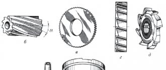
Cylindrical cutters are installed in a well-known manner on mandrels supported by one or two supports (earrings). It should be taken into account that for normal milling and high surface quality it is necessary to ensure:
- sufficient rigidity of the mandrel, so try to reduce the distance from the end of the spindle to the cutter and to the shackle as much as possible;
- the accuracy of tool rotation is the smallest runout of its teeth. For this, in addition to the correct sharpening of the cutters, the straightness of the mandrels, the accuracy and cleanliness of the ends of the spacer rings are very important. Store the mandrels carefully.
- Face milling cutters are fixed in spindles using mandrels with drivers, which fit into the spindle keys with grooves, and guide the cutter with protrusions. It is also possible to mount large diameter cutters.
Processing of spiral surfaces using a dividing head
The smoothness of the feed when milling spiral surfaces is directly dependent on the number of revolutions of the lead screw per revolution of the product: the larger it is, the smoother the cutting and vice versa. Based on this, it is recommended not to exceed the following values of the spiral inclination angle:
- with product diameter 6..10 mm…….10°
- with a product diameter of 10..15 mm…….25°
- with a product diameter of 15..150 mm….45°.
Cooling of cutters during cutting (Fig. 27) Cooling is applied only to cutters made of high-speed steel and when processing steel. The coolant is supplied from a reservoir at the base of the machines by an electric pump, which, together with the pipeline, is located in a niche at the back of the frame under the cover. The outer part of the pipeline is equipped with a metal tip with a nozzle and a valve for regulating the fluid flow.
The used liquid is returned to the base reservoir, passing through settling tanks that retain metal particles.
The tank should be flushed and settling tanks emptied as needed.
Technical characteristics of the machine 6R81G
| Parameter name | 6Р81 | 6R81G | 6Р81Ш |
| Basic machine parameters | |||
| Accuracy class according to GOST 8-71 and GOST 8-82 | N | N | P |
| Dimensions of the working surface of the table (length x width), mm | 1000 x 250 | 1000 x 250 | 1000 x 250 |
| The smallest and largest distance from the end of the spindle to the table | – | – | – |
| The smallest and largest distance from the spindle axis to the table | 50..370 | 50..400 | 50..400 |
| Distance from the spindle axis to the trunk, mm | 142 | 142 | 142 |
| Distance from the axis of the vertical spindle to the rack guides, mm | – | – | 245..845 |
| Desktop | |||
| Maximum load on the table (center), kg | |||
| Number of T-slots Dimensions of T-slots | 3 | 3 | 3 |
| Maximum table longitudinal movement (X axis), mm | 630 | 630 | 630 |
| Maximum table transverse movement (Y-axis), mm | 200 | 200 | 200 |
| Maximum table movement vertical (Z axis), mm | 320 | 350 | 350 |
| Maximum table rotation angle, degrees | ±45 | No | No |
| Price of one division of the table rotation scale, degrees | 1 | No | No |
| Moving the table by one dial division (longitudinal, transverse), mm | 0,05 | 0,05 | 0,05 |
| Moving the table by one division of the dial (vertical), mm | 0,025 | 0,025 | 0,025 |
| Table movement per one revolution of the dial, longitudinal and transverse, mm | 6 | 6 | 6 |
| Movement of the table per one revolution of the dial, vertical, mm | 3 | 3 | 3 |
| Spindle | |||
| Spindle speed, rpm | 31,5..1600 | 31,5..1600 | 31,5..1600 |
| Number of spindle speeds | 18 | 18 | 18 |
| Spindle end sketch | 45 GOST 836-72 | 45 GOST 836-72 | 45 GOST 836-72 |
| Spindle taper | 45 | 45 | 45 |
| Turning spindle cone | – | – | 40 |
| Machine mechanics | |||
| Fast table travel longitudinal and transverse, mm/min | 3150 | 3150 | 3150 |
| Fast table travel vertical, mm/min | 1050 | 1050 | 1050 |
| Number of table feed stages | 16 | 16 | 16 |
| Working feed limits. Longitudinal and transverse, mm/min | 25..800 | 25..800 | 25..800 |
| Working feed limits. Vertical, mm/min | 8,3..266,7 | 8,3..266,7 | 8,3..266,7 |
| Feed stops (longitudinal, transverse, vertical) | There is | There is | There is |
| Locking manual and mechanical feed (longitudinal) | No | No | No |
| Locking manual and mechanical feed (transverse, vertical) | There is | There is | There is |
| Spindle braking (clutch) | There is | There is | There is |
| Overload protection (ball pair) | There is | There is | There is |
| Drive unit | |||
| Main motion drive electric motor, kW | 5,5 | 5,5 | 5,5 |
| Feed drive electric motor, kW | 1,5 | 1,5 | 1,5 |
| Electric coolant pump Type | X14-22M | X14-22M | X14-22M |
| Electric coolant pump, kW | 0,12 | 0,12 | 0,12 |
| Coolant pump capacity, l/min | 22 | 22 | 22 |
| Dimensions and weight of the machine | |||
| Machine dimensions (length width height), mm | 1480 x 1990 x 1630 | 1480 x 1990 x 1630 | 1480 x 2045 x 1890 |
| Machine weight, kg | 2280 | 2210 | 2530 |
Bibliography:
Cantilever milling machines 6Р81Г, 6Р81, 6Р11, 6Р81Ш. Operation manual RE, 1983
Avrutin S.V. Fundamentals of Milling, 1962
Avrutin S.V. Milling, 1963
Acherkan N.S. Metal-cutting machines, Volume 1, 1965
Barbashov F.A. Milling business 1973, p.141
Barbashov F.A. Milling work (Vocational education), 1986
Blumberg V.A. Milling machine handbook, 1984
Grigoriev S.P. Practice of coordinate boring and milling work, 1980
Kopylov R.B. Working on milling machines, 1971
Kosovsky V.L. Handbook of a young milling operator, 1992, p. 180
Kuvshinsky V.V. Milling, 1977
Nichkov A.G. Milling machines (Machinist's Library), 1977
Pikus M.Yu. A mechanic's guide to repairing metal-cutting machines, 1987
Plotitsyn V.G. Calculations of settings and adjustments of milling machines, 1969
Plotitsyn V.G. Setting up milling machines, 1975
Ryabov S.A. Modern milling machines and their equipment, 2006
Skhirtladze A.G., Novikov V.Yu. Technological equipment for machine-building industries, 1980
Tepinkichiev V.K. Metal cutting machines, 1973
Chernov N.N. Metal cutting machines, 1988
Frenkel S.Sh. Handbook of a young milling operator (3rd ed.) (Vocational education), 1978
Related Links. Additional Information
Home About the company News Articles Price list Contacts Reference information Download passport Interesting video KPO woodworking machines Manufacturers
Technical indicators
Let's analyze each indicator separately.
Accuracy, table characteristics
Machine of normal accuracy class according to GOST 8-71. It is a universal modification (has a table rotation) of a horizontal milling machine. Overhaul cycle 26,000 hours.
Table length / width – 1000 / 250 mm has maximum movements, mm:
- longitudinal – 630;
- transverse – 200;
- vertical – 320.
Rotation range around the vertical axis: ± 45˚.
Mechanics of table movement drive
From an asynchronous electric motor (4АХ80В4; 1.5 kW; 1450 rpm), 16 stages of working movements along each axis are realized through the feed box, the denominator of the series φ = 1.26 modified.
Feed working/accelerated, mm/min:
- longitudinal – 35…1020 / 2900;
- transverse – 28…790 / 2900;
- vertical – 14…390 / 1150.
Movement per turn of the dial full / one division, mm:
- longitudinal – 6 / 0.05;
- transverse – 6 / 0.05;
- vertical – 3 / 0.025.
Main drive mechanics, spindle
The box provides 16 speeds from 50 to 1600 rpm, φ = 1.26. At minimum speed, efficiency η = 0.84; the lowest efficiency at 1600 rpm is 63%. The power of the main electric motor is 5.5 kW (4A112M4; 1450 rpm).
The end of the spindle is made with an internal taper of 7:24, seat cone 45 GOST 836-72 (replaced by 24644-81), dimensions correspond to the ISO analogue. There is a 19M6 groove at the end, through which the torque is transmitted to the mandrel tenon. Tools are fastened manually using a tightening rod (screw).
Fig.1. Table grooves (a), spindle mounting dimensions (b)
Restrictions
Based on the strength of the spindle drive mechanisms, for the frequency range 63 – 100 rpm, the cutting power is no more than 3 kW. Limit values corresponding to other speeds are indicated in the operating instructions.
Allowable cutter diameter, mm:
- end cutting for rough cutting of steel – 125;
- cylindrical when cutting cast iron – 100.
When finishing, it is possible to use Ø 160 socket heads. In all cases, the feed force should not lead to the activation of the safety clutch and exceed the permissible values, kgf: 1150 / 1000 / 850 - longitudinal / transverse / vertical, respectively.
Weight and dimensions
Dimensions at table position: length / width / height, mm:
- central – 1480 / 1990 / 1630;
- in extreme positions – 2130 / 1990 / 1630;
- rotated by ±45 – 2284 / 1990 / 1630.
The equipment belongs to the middle class by weight, weight – 2210 kg. In medium conditions, a concrete screed thickness of at least 150 mm can be installed directly on the floor without fastening.
Electric scheme
Starting engines
Power supply from the network to the spindle motor M2 is carried out by switching the circuit breaker B1. By closing the reverse - B4, the direction of rotation is selected. The cooling pump motor M1 is prepared by turning on B3 and starts together with M2.
Motors: M2, M3 (feed) are started by buttons KnP1, KnP2 using magnetic starters P1, P2, P8 sequentially one after another. M3 cannot be turned on when M2 is not working.
The KnT button (“spindle push”) implements a short jog start M2, which ensures switching of rotation speed steps when the teeth mismatch. By closing by pressing KnT, P1, P8 are energized, which with normally open contacts (8-9) trigger the PB relay. Next, the RV turns off these starters by switching its own normally closed contact (10-11), so the duration of operation of the M2 motor is not related to the time the KnT is held pressed.
Stopping, braking, protection
“General stop” is carried out using the KnS button or by pressing switch B5. When the power supply to M2 is interrupted, the main drive is braked by turning on the electromagnetic clutch EM. Direct current (-24V) comes to the EM coil from the VP rectifier. The duration of power supply is set by the PB settings.
Magnetic starters provide zero protection for electric motors. The event of a short circuit causes automatic opening of switch B1, blowing of fuses Pr1, Pr2, thereby preventing damage to electrical equipment. During prolonged operation at the power limit, overheating of the electric motors limits the operation of thermal relays P3-P5.
Fig.6. Basic electrical diagram.
Review of the 6Р82 machine: design, specifics, technical characteristics
The machine model 6Р82 with a horizontal spindle belongs to the category of cantilever milling equipment. The Gorky Milling Machine Plant specializes in the production of such units. They are designed for milling workpieces and parts of various shapes made of ferrous, non-ferrous metal or cast iron.
Design and its specifics
The 6P82 cantilever milling machine has a standard layout. The horizontally located spindle of the equipment has a rigid fixation. The position of the part changes due to the displacement of the table in different planes.
Material processing can be performed with disc, shaped, cylindrical and end mills of various configurations. The design of the 6P82 universal horizontal milling machine provides the ability to operate in both manual, semi-automatic and automatic modes. Thanks to this, the equipment is used to complete serial and piece production.
Technical features include the following characteristics:
- wide range of table feed values in almost all directions;
- automatic supply of lubricating fluid to critical moving parts of the unit;
- high-speed magnetic couplings increase productivity;
- the ability to move the desktop simultaneously in several coordinates;
- The package includes a DC electric motor that drives the feed;
- modernization opportunities. An electronic program control unit can be installed in the standard design of the machine.
It is also worth noting the duplication of the control system. It consists of installing buttons on the front of the machine and on the side.
To quickly change the position of the workpiece or cutting tool, a direct current quick stop mechanism is provided.
Machine Specifications
According to the accepted classification, the 6P82 horizontal milling machine is assigned accuracy class “H”. Its dimensions in working condition are 230.5*195*167 cm. At the same time, the weight of the structure is 2900 kg. The maximum load on the work table should not exceed 250 kg at the center.
The surface size of the work table is 125*32 cm. To fix the workpiece, it has 3 T-shaped grooves. Characteristics of moving the desktop, see:
- transverse – 24/25;
- longitudinal – 80/80;
- vertical – 36/37.
Thanks to the versatility of the design, the table can be rotated 45°.
The horizontal spindle of the 6P82 machine has standard characteristics for this type of equipment:
- rotation speed variability - from 31.5 to 1600 rpm;
- the number of speeds is 18;
- at maximum speed the torque is 107 kg/m;
- spindle cone - 50.
The advantages of operation include multifunctional mechanics of operation and improved accuracy characteristics. They consist of the presence of switching feed stops for all directions, the possibility of manual and mechanical locking, and the mode of intermittent longitudinal and transverse feed. In addition, when the machine is operating, it is possible to quickly stop the spindle and protect the clutch from overloads.
To operate the machine, its design contains two electric motors - the main drive and the feed. The power of the first is 7.5 kW, the second – 2.2 kW. Additionally, there are pumps for supplying coolant and coolant.
The video shows an example of how the machine works:
Location of controls for the milling machine model 6R81G
Location of controls for milling machine 6р81г
List of controls for the 6Р81G machine and their purpose
- Circuit breaker
- Cooling pump switch
- Spindle rotation direction switch
- Spindle start button
- Feed Start Button
- "General stop" button
- Spindle Jog button
- Spindle speed shift knob
- Spindle shift knob
- Table feed switch handle
- Feedbox shift knob
- Mechanical vertical feed activation handle
- Mechanical cross feed switch handle
- Mechanical longitudinal feed switch handle
- Flywheel for manual longitudinal movement of the table
- Handle for manual vertical movement of the table
- Handwheel for manual lateral movement of the table
- Rapid feed switch in all directions
- Handle for securing the table against vertical movement
- Handle for securing the table against longitudinal movement
- Handle for securing the table against lateral movement
- Stops for turning off the longitudinal mechanical movement of the table
- Stops for switching off the transverse movement of the table
- Stops for switching off the vertical movement of the table
- Manual lubrication pump drive handle
- Local lighting switch
- Trunk movement square
- Square for securing the trunk
- Screws and nuts for securing the upper slide against rotation (for machine 6P81)
- Earring fastening nut
- Handwheel for moving the quill
- Quill clamp handle
- Square head rotation
- Speed shift handle for the rotary spindle of the slider
- Rotary spindle rotation direction switch
- Switch for selecting spindle operation (horizontal, rotary or both)
- Handwheel for switching on and regulating the supply of coolant
General technical specifications
The main parameter of the equipment is the horizontal spindle, which does not change its location.
The machine table is manufactured with an angle of movement relative to the axial shaft; movement is carried out along, perpendicularly, horizontally. With minor modernization, the unit can be completed and the rotating capabilities of the table can be expanded.
The machine was produced for processing spiral grooves of various blanks, planes, grooves, frames, corners, solid plates, etc. The design of the table allows it to be rotated 180–360 degrees.
Characteristics of the 6P81 spindle:
- Speed – 16 subsystems. Maximum vertical 1050 mm per minute, horizontal 3150 mm per minute.
- Rotation up to 1600 per minute.
- Cone 45.
- The specified standard for the unit is GOST 836-45.
The unit can be powered by autonomous sources. To supply power to the spindle and mechanical feeds, the use of adjacent power sources is provided.
The main motor of the machine (5.5 kW) drives the spindle, which receives the speed set by the milling operator when setting up the start.
The feed drive speed depends on the operation of the adjacent motor (1.5 kW). The required power to operate the cooling system is up to 0.12–0.14 kW.
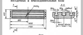
Workspace dimensions
Distance between the spindle axis and the working plane of the table, mm:
- minimum (no more) – 50;
- maximum (not less) – 370.
Distance between the vertical guides and the plane of symmetry of the central groove, mm:
- minimum – 170;
- maximum – 370.
Distance between the rear edge of the table, mm:
- and vertical guides of the bed – 45;
- and the end of the spindle - 11.
The distance between the slider (trunk) and the spindle axis is 142 mm.
The maximum distance between the ends of the shackle bearing and the spindle is 495 mm.
Rice. 2. Limits of the working area
Characteristics of the 6N81G milling machine.
The 6N81G horizontal cantilever milling machine is designed for processing various relatively small-sized products made of steel, cast iron, non-ferrous metals and plastics, mainly with cylindrical, end, disk, corner, shaped and modular cutters with special cutters in individual and mass production. The machine is designed for processing flat and shaped surfaces, gears, etc. The presence of a rotary table allows you to cut helical grooves in the manufacture of helical wheels, cutters, countersinks, reamers and similar parts.
Explanation of the machine name:
6 — milling machine (group number according to ENIMS classification)
N – series (generation) of the machine (B, K, N, M, R, T)
8 – subgroup number (1, 2, 3, 4, 5, 6, 7, 8, 9) according to the ENIMS classification (8 – horizontal milling)
1 – machine version – standard size (0, 1, 2, 3, 4) (1 – work table size – 250 x 1000)
G – horizontal cantilever milling machine with a fixed table
A wide range of spindle speeds and table feeds provides the ability to process products at optimal cutting conditions.
For spindle rotation and mechanical table feeds, drives from separate electric motors are provided. The machine table can make rapid movements in three directions.
Manual and mechanical drives are interlocked. The mechanical movements of the table can be switched off using stops or manually. An electromagnetic clutch is used to brake the spindle.
The increased power of electric motors and the rigidity of the machine ensure the processing of products. at high-speed cutting modes with carbide tools.
The machine can be used in single small-scale and mass production.
The technical characteristics of the machine are given in Table 2.
| table 2 | |
| Basic machine parameters | |
| Accuracy class according to GOST 8-71 and GOST 8-82 | N |
| Dimensions of the working surface of the table (length x width), mm | 1000 x 250 |
| The smallest and largest distance from the spindle axis to the table | 30..380 |
| Distance from the spindle axis to the trunk, mm | 150 |
| Desktop | |
| Number of T-slots Dimensions of T-slots | 3 |
| Maximum longitudinal movement of the table by hand/by motor (X-axis), mm | 600/ 560 |
| Maximum table transverse movement by hand/by motor (Y-axis), mm | 200/ 190 |
| Maximum vertical movement of the table by hand/by motor (Z axis), mm | 400/350 |
| Moving the table by one dial division (longitudinal, transverse), mm | 0,05 |
| Continuation of Table 2 | |
| Moving the table by one division of the dial (vertical), mm | 0,025 |
| Table movement per one revolution of the dial, longitudinal and transverse, mm | 6 |
| Movement of the table per one revolution of the dial, vertical, mm | 3 |
| Spindle | |
| Spindle speed, rpm | 65..1800 |
| Number of spindle speeds | 16 |
| Spindle end sketch | GOST 836-47 |
| Spindle taper | 45 |
| Maximum permissible torque on the spindle Nm | 525 |
| Machine mechanics | |
| Rapid table travel longitudinal (X axis), m/min | 2,9 |
| Fast table travel transverse (Y axis), m/min | 2,3 |
| Rapid table travel vertical (Z axis), m/min | 1,15 |
| Number of table feed stages | 16 |
| Working feed limits. Longitudinal (X axis), mm/min | 35..980 |
| Continuation of Table 2 | |
| Working feed limits. Transverse (Y-axis), mm/min | 25..765 |
| Vertical (Z axis), mm/min | 12..380 |
| Feed stops (longitudinal, transverse, vertical) | There is |
| Locking manual and mechanical feed (longitudinal) | No |
| Locking manual and mechanical feed (transverse, vertical) | There is |
| Spindle braking (clutch) | There is |
| Overload protection (clutch) | There is |
| Drive unit | |
| Main motion drive electric motor, kW | 4,5 |
| Feed drive electric motor, kW | 1,7 |
| Electric coolant pump Type | PA-22 |
| Coolant pump electric motor, kW | 0,12 |
| Coolant pump capacity, l/min | 22 |
| End of table 2 | |
| Dimensions and weight of the machine | |
| Machine dimensions (length width height), mm | 2060 x 1940 x 1600 |
| Machine weight, kg | 2000 |
In the frame 1 of the machine there is a gearbox 2. The console 7 moves along the vertical guides of the frame. The workpiece, installed on the table 4 in a vice or device, receives feed in three directions: longitudinal (movement of the slide in the direction of the slide 6), transverse main movement is the rotation of the spindle . Feed box 8 is located in the console. trunk 3 serves to secure the suspension 5, which supports the end of the milling mandrel. The layout of the 6N81G machine components is shown in Figure 2.
Fig.2. Layout of machine components 6N81G.
Application area
Horizontal milling universal machines are designed for efficient processing of parts made of ferrous, non-ferrous metals, alloys, and plastics with high-speed and carbide tools. It is rational to load small and medium-sized workpieces without crust with moderate allowances. Optimal scope of application:
- repair;
- single;
- small-scale production.
It is justified to use it in serial metalworking in individual operations, with a small number of working tools, when loading CNC equipment is unprofitable or the latter is absent.
Used for processing horizontal surfaces with cylindrical cutters on a mandrel with support. It is possible to mill planes, grooves, and shoulders with an end tool installed in the spindle cone. Using socket heads, allowance is removed from the vertical planes of the parts. Cut-off disc cutters separate the material, mill grooves, grooves, including spiral ones, on shafts installed in the centers of the dividing head. In the repair business, gears are cut with a modular tool. Technological capabilities are expanded by using round and globe tables, optical heads, and boring equipment.
General technical characteristics of the 6P81 model
One of the key characteristics of the 6P81 is the main spindle. It never changes its position in the device. And the base of the 6P81 cantilever milling machine is a rigid bed. It is cast from a special alloy, which gives additional rigidity to this device. And the ribs can strengthen the platform for installing the device. Thus, the device will not move anywhere during its operation and its mechanisms will not be damaged by the trembling that occurs during the operation of the unit.
A pair or one earring is mounted in the cone of the 6P81 device. The device has additional capacity. It is created for a liquid that will cool the metal during operation. The spindle speed of such a machine is 1050 millimeters per minute - vertical, and horizontal - 3150. The spindle makes up to 1600 revolutions per minute. And the machine is powered by electrical circuits that ensure the use of adjacent sources of electricity.
The platform or table on which the cantilever horizontal milling machine is installed can be moved relative to the shaft axis. This means that perpendicular and horizontal metal processing is possible. Rotating the table produces high-speed movements in three directions and helps to process spiral grooves on cylinders, gears, and frames well.
Electrical diagram of the 6Р81 machine
Desk dimensions
There are several types of milling machines of this brand. One of these types is the 6P81 cantilever horizontal milling machine. According to its passport, the dimensions of its working area are as follows:
- Table size – 1000×250.
- The axis travel is 710 millimeters.
- Perpendicular movement has the following value - 2 =50.
- The spindle trunk is 142 millimeters.
- Processing clarity according to class N.
- The vertical feed during operation is two hundred and sixty-seven millimeters, and the horizontal feed is eight hundred.
- Friction parameters are equal to V4, V5.
Using this equipment you can cut products made of hard alloys. And the cooling elements of the machine will allow its cutting heads to last a long service life.
Download the passport (operating instructions) of the 6P81 cantilever milling machine