Milling machines are designed for processing metal and wooden workpieces using a milling cutter. The milling operation involves the rotational movement of the cutting tool, which is the main one, and the translational movement of the workpiece or milling head, which is called the feed movement.
1. Milling machines are used to perform the following operations:
- processing of external and internal flat surfaces;
- creation of shaped surfaces;
- cutting grooves, external and internal splines, grooves;
- creation of involute and other gear profiles;
- cutting ends and creating profiles on end surfaces;
- cutting off
Let's consider the main parameters by which milling machines are classified.
2. Depending on the location and direction of movement of the spindle, they are divided into two large groups:
- vertical milling;
- horizontal milling;
- combined.
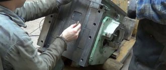
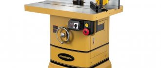
Vertical milling machines (Fig. 1) have a spindle, the axis of rotation of which is located vertically. Some modifications of these machines are additionally equipped with a mechanism for rotating the spindle around a horizontal axis. This allows you to change the angle of application of the cutter, which will significantly expand the capabilities of the machine. Also, the spindle on some machines has the ability to move along the axis of rotation, as well as to carry out movements in the horizontal plane, which also increases the technological capabilities of the machine.
Figure 1. Vertical milling machine.
Figure 1. Vertical milling machine.
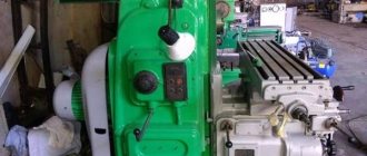
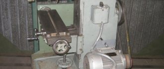
In horizontal milling machines (Fig. 2), the axis of rotation of the spindle is located horizontally. This somewhat limits the scope of application of this machine. But at the same time, it increases the list of operations that it is capable of performing. For example, a horizontal milling machine can perform surface grinding or polishing.
Figure 2. Horizontal milling machine.
Figure 2. Horizontal milling machine.
Combined machines are distinguished by the presence of a movable milling head, which is capable of changing its position, positioning the spindle in relation to the workpiece vertically or horizontally, depending on the required operation.
3. Depending on the scope of application:
- universal;
- specialized.
4. According to the presence of the console:
- console;
- non-console.
In console machines, the table is mounted on a movable console, which can move in three coordinates. On non-cantilever versions of milling machines, the table is mounted on a bed and can only move in the horizontal direction along guides.
5. By type of control:
- with manual control;
- semi-automatic;
- automatic (CNC machines).
Let's take a closer look at each of the most popular types of milling machines.
Cantilever vertical milling machine
A vertical milling machine with a console is one of the most common. This popularity is due to the fact that, despite its rather simple design, this machine is capable of performing most of the most popular milling operations.
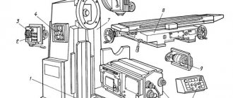
Let's consider the general design of a cantilever vertical milling machine (Figure 3).
Figure 3. Design of a cantilever vertical milling machine.
Figure 3. Design of a cantilever vertical milling machine.
A vertical milling machine with a console consists of the following elements.
- Console. A complex mechanism that ensures that the workpiece is fed to a rotating cutter with the required pitch and speed. In most cases, it has settings for a semi-automatic processing mode, which allows you to select the direction and feed rate, as well as the depth of cutter penetration depending on the spindle speed.
- Sled. Designed to move the table.
- Table. Serves to secure the workpiece being processed.
- Protective shield. Protects the milling operator from flying chips.
- Spindle. Transmits movement from the machine drive to the cutter. Can be adjusted in height and angle of inclination relative to the workpiece.
- Milling head. Contains mechanisms for reversing and changing the spindle speed.
- Crawler. Movable part of the milling head. Feeds the cutter in the vertical direction.
- Bed. The base of the machine on which all components and mechanisms are located.
- Casing. Protects console components from chips.
- Closet. Serves to accommodate electrical equipment.
Vertical milling machines can be equipped with additional equipment or have expanded capabilities due to the introduction of additional options.
Machine overview
Before deciding which milling machine to choose to equip a home workshop or manufacturing plant, it is important to familiarize yourself with the characteristics of the equipment that is offered on the modern market. Today, the most popular are milling machines produced in the following countries:
- Germany;
- Italy;
- Austria;
- China;
- North Korea;
- Malaysia;
- USA;
- Taiwan;
- Czech Republic;
- Türkiye.
Five-axis milling machine
The most famous companies that produce and sell CNC milling machines are:
- GCC Jaguar;
- Redwood;
- RuStan;
- JCC;
- Hyundai Wia;
- Kami;
- Zenitech.
Some of the fastest machines, which also feature a wide variety of settings and additional functions, are models of the GCC Jaguar brand.
JCC is distinguished by its wide variety of machines for processing parts made of metal and other materials. The catalog of this manufacturer presents CNC machines for the following purposes:
- universal type, designed for engraving and milling work;
- for processing wood and metal products;
- piercing machines of electroerosive type;
- equipment for milling and turning group.
Advanced software products that control the machines of this brand allow you to use their full potential.
CNC vertical milling machine MA655
CNC-equipped milling machines of the RuStan brand are primarily equipment of a highly versatile type, with which you can perform a wide range of technological operations. What makes the models of this brand different is that when purchasing them you can take advantage of a variety of discount programs, as well as the possibility of warranty and post-warranty service.
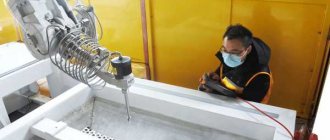
Truly unique are the CNC milling machines produced under the Redwood brand. They are capable of processing parts in 2d and 3d format. The implementation of 3D technology assumes that, according to a given program, a volumetric part is obtained from a workpiece that fully corresponds to the given geometric parameters.
The main principle of the work of specialists involved in the production of milling equipment of the Kami brand is the production of high-quality products. Using machines of this brand, you can process not only metal, but also parts made of stone, wood, plastic and even glass.
Hyundai Wia specializes in the production of CNC machines that produce products for the aerospace and automotive industries. The programs that are used to control them require minimal human intervention and greatly simplify the use of such equipment.
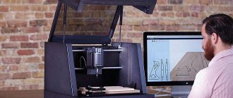
Milling machine from the German manufacturer Zenitech
The catalog of the well-known manufacturer Zenitech is dominated by professional CNC milling equipment designed for processing metal and wood parts.
CNC milling equipment of the Invest Adam brand is widely represented on the modern market. The main advantages of the models, which are distinguished by their compactness and versatility, are:
- high processing accuracy;
- efficiency and productivity;
- control programs can be played repeatedly;
- the design is highly reliable;
- communication with the computer that controls the operation of the equipment is carried out via a regular USB port.
To equip a home workshop and a large manufacturing enterprise, you can use a CNC milling machine produced by the German company BZT. The machines of this brand are distinguished by high stability, reliable fixation of workpieces, accuracy and efficiency of processing. It is also convenient that the machines of this brand can run on almost any software.
The cost of a CNC milling machine is influenced by the following parameters:
- complexity of equipment design and its type;
- type of production for which the equipment is intended;
- country of origin and brand;
- functionality of the machine.
The simplest design is available on desktop CNC machines, which are much cheaper than more functional equipment. To save on purchasing a milling machine, choose equipment from domestic manufacturers. On average, the cost of desktop CNC milling equipment is about $4,000. This price can vary depending on a number of factors: dimensions of the machine and work table, engine power, weight of the equipment and its functionality.
The cost of equipment for a CNC vertical milling group varies from $7,000 to $25,000. The price of a specific equipment model depends on its power, the number of spindle revolutions and processing accuracy.
Domestic machine GF2171
Large-format CNC-equipped milling machines are the most expensive in their category, as they allow a wide range of technological operations. The high cost of such equipment is compensated by the fact that it can be operated in a fairly intensive mode. The list of operations that can be performed using equipment of this category is impressive:
- cutting blanks;
- milling of various types of surfaces;
- polishing operations;
- drilling;
- boring operations.
Horizontal milling machine
A horizontal milling machine (Fig. 4) is distinguished by the horizontal arrangement of the cutter. As a rule, the cutter is fixed motionless, and feed is carried out only by moving the table.
Figure 4. Design of a horizontal milling machine.
Figure 4. Design of a horizontal milling machine.
A horizontal milling machine consists of the following elements.
- Gear shift knob. Serves to switch spindle rotation modes.
- Bed. It is the supporting structure of the machine on which the working elements are located.
- Limbo. Used for fine tuning.
- Trunk. Designed to secure the second end of the cutter drive shaft.
- Gearbox. Consists of a set of gears with a rocker shift mechanism. Serves to change the rotation speed of the cutter.
- Spindle. Designed to secure the cutter drive shaft in it.
- First pendant.
- Second pendant. Both suspensions are designed to fix the drive shaft.
- Table. Serves to secure the workpiece being processed.
- Rotary plate. Capable of rotating around a horizontal axis.
- Sled. Necessary to ensure horizontal feed of the part.
- Console. A complex device that functions as a part feeding mechanism in all planes. The specifics of the operation of a horizontal milling machine do not allow, in the usual case, to give mobility to the cutter. Therefore, all movements of the cutter relative to the workpiece are carried out through the console.
- Gearbox. Serves to configure automatic longitudinal and transverse feed.
- Foundation slab. Machine base. Has holes for fixing the machine to the foundation.
- Feed control handle. Controls the feed rate.
- Feed dial. Designed to adjust feed with increased accuracy.
Purpose
The cantilever milling machine is designed to perform the corresponding work using face, disk, corner and other cutters. The equipment can process various workpieces of suitable size. Material suitable for participation in the work process is cast iron, non-ferrous metals, plastic, steel and other alloys.
On analogues with a rotary table, it is possible to process screw sockets on the cutting parts of the tool. Universal models are designed to carry out a variety of milling operations, including boring and drilling work in experimental or individual production conditions. The complexes are often used in large-scale production of various parts.
Speed box
The speed switching unit of a wide-universal cantilever milling machine is located in a cast iron body; aggregation with the speed shaft is carried out through an elastic coupling. The spindle of the block in question is a shaft with three support points. Its accuracy is determined by special bearings. Another element is designed to hold the shank of this assembly.
The axial clearance is adjusted by grinding the locking rings. Increased play can be removed by processing the half rings and the fixing nut. A plunger pump with a capacity of 2 liters per minute is responsible for lubricating the gearbox. The remaining parts of this mechanism receive lubrication by splashing from a tube located above the speed control unit.
Setting Automatic Mode
For cantilever milling machines of the “M” and “P” modifications, the longitudinal movement of the table is adjusted in automatic or semi-automatic mode. In single production, feed control is performed manually, including rapid table movement. Serial production involves the use of automatic and semi-automatic ranges. In essence, these modes represent a spasmodic and pendulum mode of action.
To adjust the process accordingly, the distance between the cams is made in a T-shaped slot on the side according to a certain indicator. At the right moment, these elements act on the control sprocket with quick working movements of the table on the longitudinal feed switching handle, which makes it possible to guarantee the operation of the equipment according to a given cycle.
The main operating cycles of a cantilever milling machine are listed below:
- Jumping semi-automatic mode.
- Quick feeds to the right and left back.
- A similar operation to the left and the opposite direction to the right.
- Active feeding of the workpiece followed by stopping.
- Pendulum automatic cycle.
- Operations on the machine are only in the right or left direction.
The setup process is carried out in the following sequence:
- The machine must be disconnected from the power supply.
- The mode switches are placed in the desired position (“Automatic control”).
- The unit is activated by pressing the “On” button.
- The cams are installed in the appropriate position.
- Feeding to high speed and back is carried out at any stage and direction of movement, with the exception of the restriction zone for possible operation of the elements.
- Correction of automatic or manual movement of the table is carried out in a neutral position by longitudinally pressing the handle until it stops. If it is impossible to fix the flywheel at the end, turn the adjusting screw.
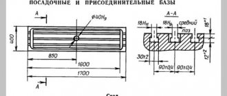
Parameters of model 6Р82 and 6Р82Г
For comparison, let's look at the two most popular machine models. Let's start with the characteristics of the 6P82 modification:
- Length/width of the desktop – 1.25/0.32 m.
- Number of T-slots – 3.
- Dimensions – 2.3/1.95/1.67 m.
- Weight – 2.9 tons.
- The spindle braking mechanism is present.
- The maximum weight of the processed workpiece is 250 kg.
- The movement of the dial per revolution (longitudinal/vertical) is 6/2 mm.
- The distance from the axis to the trunk is 155 mm.
- Longitudinal/transverse movement of the table – 800/240 mm.
The 6R82G modification differs only in weight (2.83 tons), as well as the maximum distance from the horizontal spindle to the working surface (450 mm).
Work tool
Cantilever and non-cantilever, conventional vertical milling or ultra-modern CNC machines cannot do without the main part - the cutting tool. It consists of a variety of cutters made from high-quality steel, which allows processing any metals and surfaces. Any type of processing tool is rigidly fixed in the spindle (mainly by a jaw chuck), which guarantees precision processing.
A brief list of possible processing planes and the cutting tools required for this is as follows:
- horizontal – end mills of various configurations;
- inclined - end and end;
- vertical surfaces and surfaces with ledges - end mills;
- milling of grooves of any configuration - end or single-angle cutters;
- machining of cylindrical gears – finger tool.
For milling complex surfaces that combine sections of various types (convex, straight or concave, with ledges or recesses), the use of modern cantilever milling units equipped with CNC has proven to be more effective. However, it is also possible to produce parts of this type on a conventional vertical milling machine, although it takes a little more time. To do this, it is necessary to draw up a special processing scheme for the workpiece and an equation for manufacturing a part of complex shape.
When developing an equation, the following parameters must be taken into account:
- roughness indicators of the resulting part;
- cutter radius;
- thickness of the processed material;
- amount of feed of the workpiece to the cutter;
- thickness of the removed chips (comb height);
- different axial angles of rotation of the tool.
The quality of processing, characterized by the amount of roughness, depends to the greatest extent on the angle of rotation of the cutter and the amount of feed of the workpiece. Other factors also have an impact, but much less.
High-precision vertical milling machines sold by our company allow us to minimize wasted time and reduce the amount of waste generated during milling of both individual parts and entire batches. This results in significant cost savings for the entire enterprise.
CNC modifications
Cantilever milling machines of this type are equipped with an electric motor with a power of 5.5 kW with a speed of 1450 rotations per minute. They are widely used in mechanical engineering and industry. The working movement is transmitted through two types of gears: 35/27 or 21/41. The diagram of a cantilever milling machine indicates that the number of the shaped gear depends on the number of teeth. Thus, the equipment can operate at two different speeds. The correct operation of the tool depends on the constant module of the gear coupling, which must be stable with a pair of wheels aggregating among themselves.
The kinematic diagram of the machine includes a structural diagram when the spindle rotates. In this case, the speed grid is related to the number and rating of gears engaged. The distance between the vertical and horizontal guides depends on the selected scale during the work.
Gearbox
This unit provides working feeds and high-speed movements of the console, slide and table. When moving, impulses are transmitted to the shaft using a safety clutch and bushing, which are connected to each other by means of a key and the output shaft. The disk part of the friction block aggregates with a bushing and a roller. When the clutch cam is activated, force is transmitted to the nut, gears and discs.
The feed switching box of the universal cantilever milling machine is located in the frame. The operating principle of this unit is similar to the speed unit. The disk is protected from axial displacement by a roller, which is locked with a pair of balls and a bushing. The disk is locked using identical parts connected to the shaft via a key.
Peculiarities
Technologically, the “P” series models are more improved in terms of the longitudinal travel of the worktable (by 100 mm). Precise installation of the surface is carried out using modernized mounting of the limbs. In addition, this equipment has an optimal configuration that meets modern standards of technical aesthetics. All main components of the machines under consideration are unified with each other.
Additional convenience when working and managing the “M” and “P” versions is provided through an automated cycle and options such as:
- Duplication of the controller for the number of spindle revolutions and table feed.
- Possibility of selectively setting the required number of rotations of the axis or dial.
- There is no need to go through intermediate steps when performing manipulations.
- The table is automatically moved from the handles, the direction of which is similar to the movement of the working surface.
- There is a spindle start and stop in accelerated mode using special buttons and direct current.
- The table can move in vertical, horizontal and longitudinal projection.