Author of the article:
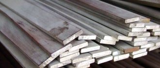
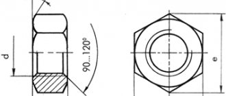
Bolts are among the most common and popular fastening elements in various fields of activity, ranging from mechanical engineering and construction to minor home repairs. The bolt appears as a threaded rod of metal with a head shaped to provide a secure grip for the tool to provide torque. The most common versions of such hardware have hex heads - a turnkey size of the appropriate size.
Marking of high strength bolts
There are many classifications that use different designations for high-strength bolts. But the most significant characteristic by which they are distinguished and divided into groups is the strength of the bolts in relation to physical pressure. Resistance to such effects characterizes the functional potential of the hardware and its service life. It also covers the ability of a fastener to withstand changes in temperature and other artificial and natural phenomena.
Here are some of the notations used:
| Strength class | Material of manufacture | Main sizes |
| Bolts of strength class 8.8 | 40X | M30-M64 |
| 40ХН2МА | M30-M64 | |
| 40ХН | M30-M64 | |
| Bolts of strength class 10.9 | 40X | M12-M36 |
| 40ХН2МА | M24-M48 | |
| Bolts of strength class 12.9 | 40X | M12-M30 |
| 40ХН2МА | M24-M36 |
Hardware with strength class 8.8 is made from hardened steel and is suitable for most construction and installation work. Bolts of a higher strength class are designed not only for constant load, but also for variable pressure, therefore they are used in structures of increased complexity, as well as where regular installation and dismantling of individual elements is planned.
Operation of High Strength Bolts (Spheres, Areas and Examples)
The use of high-strength bolts is often found in such areas as construction, road equipment manufacturing, instrument and mechanical engineering, as well as other production-related areas. The high demand for them is due to the fact that such hardware has practically no restrictions on use and is used in toxic aggressive environments and at low temperatures (down to −60C).
High-strength fasteners can withstand both constant and variable loads, with a moving center of gravity, and even strong vibrations. Therefore, with the help of these hardware, buildings are built, industrial equipment, heavy equipment (including military) and special purpose vehicles (cranes, loaders, etc.) are manufactured.
How to choose?
It is easy to understand that choosing the right bolts is quite complicated
You will have to pay attention to the conditions of future use and the conditional design load at the joint. At the same time, tensile strength and tearing strength are clearly distinguished
The necessary markings must be both in the accompanying documentation and on the head of the metal product itself. Additionally, it is customary to subdivide bolts into the following categories:
- mechanical engineering;
- furniture;
- road;
- ploughshare (agricultural);
- elevator (for conveyors of bulk materials).
And there are a number of other highly specialized examples.
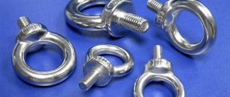
Most consumers choose fasteners with a traditional hexagonal shape. But there may be products with a countersunk head. The semicircular head is different in that the “mustache” or headrest will not allow it to rotate in the normal position. Products for particularly difficult conditions of use are equipped with a press washer.
You can learn how to polish a stainless steel furniture bolt from the video below.
High Strength Bolt Table (Standards)
| Standards | Standard sizes | Notes |
| Bolts GOST 7795-70 | M6-M48 | Instead of bolts GOST 7795-62. Hexagonal reduced head, guide support, accuracy class B. |
| Bolts GOST 7796-70 | M8-M48 | Instead of bolts GOST 7796-62. Hexagonal reduced head, accuracy class B. |
| Bolts GOST 7798-70 | M6-M48 | Instead of bolts GOST 7798-62. Hexagonal head, accuracy class B. |
| Bolts GOST 7805-70 | M2-M48 | Instead of bolts GOST 7805-62. Hexagonal head, accuracy class A. |
| Bolts GOST 7808-70 | M8-M48 | Instead of bolts GOST 7808-62. Hexagonal reduced head, accuracy class A. |
| Bolts GOST 7811-70 | M6-M48 | Instead of bolts GOST 7811-62. Hexagonal reduced head, guide support, accuracy class A. |
| Bolts GOST 7817-80 | M6-M48 | Instead of bolts GOST 7817-72. Hexagonal reduced head, accuracy class A, for reamer holes. |
| Bolts GOST 10602-94 | M52-M150 | Instead of bolts GOST 10602-72. Hexagonal head, accuracy class B, thread diameter more than 48 mm. |
| Bolts GOST 15589-70 | M6-M48 | GOST was introduced for the first time. Hexagonal head, accuracy class C. |
| Bolts GOST 15590-70 | M6-M48 | GOST was introduced for the first time. Hexagonal reduced head, guide support, accuracy class C. |
| Bolts GOST 15591-70 | M6-M48 | GOST was introduced for the first time. Hexagonal reduced head, accuracy class C. |
| Bolts GOST 18125-72 | M52-M160 | Instead of bolts GOST 10603-63, GOST 10604-63. Hexagonal reduced head, accuracy class A and B, thread diameter more than 48 mm. |
| Bolts GOST 22353-77 | M16-M48 | GOST was introduced for the first time. Hexagonal head, accuracy class B. |
| Bolts GOST R 52644-2006 | M16-M48 | GOST was introduced for the first time. Hexagonal head, increased wrench size, for metal structures. |
| Bolts OST 26-2037-96 | M16-M48 | Instead of bolts OST 26-2037-77, OST 26-01-566-72. Hexagonal head, for flange connections. |
| Bolts OST 37.001.123-96 | M6-M16 | Hexagonal reduced head. |
There are not many manufacturers of high-strength bolts, since the production of these hardware requires high-quality raw materials, and the production technologies are complex. The steel of high-strength bolts must meet a long list of requirements and limitations. Most factories producing such fasteners have their own design departments for the development of non-standard individual orders, especially for strength class 12.9. In addition, such enterprises are usually equipped with quality control laboratories for careful handling of raw materials and testing of finished products.
Rules for installing high-strength bolts
Before starting work, a preliminary analysis of the technical operating conditions of the future structure is always carried out. The selection of the required hardware will be influenced by the following factors:
- Characteristics of additional accessories.
- Twist factor.
- Correspondence of the technical and mechanical properties of the hardware to the environment in which it will work.
- Resistance to various external influences.
- Properties of the steel from which it is made.
- Thread pitch and type.
The conditions for the correct choice are also influenced by the size, shape of the bolt head, the presence of heat treatment and protective coating. Always start from the purposes for which you need hardware. The further procedure is as follows:
- The holes in the connected elements are aligned and the elements are rigidly secured using assembly plugs. Usually a tenth of the holes are secured with plugs - this is quite enough for reliable fixation.
- High-strength bolts are inserted into the holes free of plugs and tensioned in accordance with the rules and with the force specified in the technical documents.
- Then remove the assembly plugs, install the remaining bolts and tighten all the parts to the design strength. After this, the working surface can be primed.
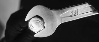
Use a calibration wrench that allows you to control and adjust the tension of the bolts.
4.2. Shear connections
4.2.1. When exposed to a longitudinal force passing through the center of gravity of the connection, the distribution of this force between the bolts should be assumed uniform. When a bending moment is applied to a connection, the distribution of forces between the bolts should be taken proportional to the distances from the center of gravity of the connection to the bolt in question (with triangular diagrams of the distribution of forces between the bolts, Fig. 2).
Rice. 2
4.2.2. Bolts that are sheared by the simultaneous action of a longitudinal force and a bending moment must be checked for the resultant force.
4.2.3. The design force (kN) that can be absorbed by one bolt should be determined using the formulas:
for cutting -
N
bs = 0.1
R
bs
γ
b1
A
n
b,(4 )
to crumple -
N
bp = 0.1
R
bp
γ
b1 γb2 γ(t)
a
b,(5)
Notations adopted in formulas (4, 5):
γ
b1 is the coefficient of working conditions, taking into account the non-simultaneous inclusion of bolts in work, which should be taken according to table. 4;
γ
b2 is the operating condition coefficient, taking into account the distances along the force from the edge of the element to the center of the nearest hole and between the centers of the holes, which should be taken according to table. 5;
A
=
nd
2/4 - design area, cross-section of the bolt rod, cm2;
n
b is the number of calculated cuts of one bolt;
γ(t) - coefficient taking into account the thickness of the elements being connected, determined
(6)
t
— the smallest total thickness of elements removed in one direction;
d
b is the nominal outer diameter of the bolt shaft, cm.
Table 4
| connection characteristics | Connection operating conditions coefficient γв1 |
| Single-bolt in shear and crush calculations | 1,0 |
| Multi-bolt in calculations for shear and crushing | 0,9 |
Table 5
| connection characteristics | Connection operating conditions coefficient γв2 |
| Single-bolt and multi-bolt based on crushing: | |
| at 1.5d ≤a | 0,25 a / |
| at a ≥ 3 | 1,25 |
Note.
Distance
b
must be greater than distance
a
by at least 0.5
d
.
Otherwise a
=
b
-0.5
d
.
The calculated forces that can be absorbed by one bolt of a multi-bolt connection per shear with one shear plane are given in.
Design forces that can be absorbed by one M24 bolt of a multi-bolt connection in collapse (at R
bp = 1.48·
R
un, a = 2
d
;
b
= 2.5
d
) are given in.
4.2.4. Number n
bolts in a connection under the action of axial force
N
(kN) should be determined by the formula
(7)
where Q
b is the lesser of the calculated forces for one bolt
N
bs and
N
bp, calculated in accordance with the requirements of these recommendations.
4.2.5. The crush movements of each element that occur during the operation of connections and from the action of standard loads should be determined:
a) at N
bp≤
N
bs - according to table.
6.
| Design collapse resistance R bp, MPa | Crumple movements of each connected element u , mm, from the action of standard loads at | ||||
| 1,0 | 1,1 | 1,2 | 1,3 | 1,4 | |
| 0,94 R un | 1,0 | 0,8 | 0,75 | 0,7 | 0,65 |
| 1,17 R un | 1,75 | 1,4 | 1,1 | 0,9 | 0,75 |
| 1,48 R un | 3,0 | 2,4 | 2,0 | 1,6 | 1,35 |
| 1,58 R un | 3,5 | 2,8 | 2,3 | 1,9 | 1,6 |
Designations adopted in table. 6:
Q
calc. — the force acting on the connection from the design loads;
Q
normal - the same from standard loads.
Note.
When determining the bearing displacements of each connected element for intermediate values
K
=
Q
calculated /
Q
norms, linear interpolation is allowed.
It is allowed to accept the values of the displacement of each connected element u
, from the action of standard loads less than those given in table. 6, while the design resistance of single-bolt connections to crushing should be determined by the formula
R
bp =
K
f
R
,
8
)
where f
— coefficient, equal to
f
= 1.08×
u
- at 0 u ≤ 0.8 mm, (9)
f
= 0.57+0.4×
u
-0.032×
u
2 - at 0.8
u
≤ 3.8 mm (10)
Factor f
depending on the displacements of the collapse of each connection of the element
u
is given in ;
b) at N
bs
N
bp - according to formulas 9, 10 and according to;
replacing N
bp in formula () with
N
bs.
4.2.6. The strength of elements weakened by holes in shear connections should be checked taking into account the complete weakening of the sections by holes.