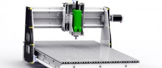
Jig boring units have a special place in the world of machine tools, because they perform one of the most difficult tasks - creating high-precision holes with minor deviations in placement relative to each other. Such equipment has a special reading device, which makes it possible to perform high-precision processing of workpieces. The error when drilling holes is up to 1 micrometer. Additionally, coordinate machines are equipped with a device that controls possible deviations, which makes the work process almost like jewelry.
This type of technique is used in the processing of center-to-center holes if it is necessary to achieve the most accurate distances in accordance with the coordinates . During the processing of workpieces, no additional structures are needed to guide the tool.
Purpose
The equipment is used to process internal cylindrical surfaces. In this case, deviations of the tool from the center of the hole are not allowed. The following types of work are performed on the equipment:
- drilling and boring holes;
- processing of external surfaces of cylindrical workpieces;
- chamfering, countersinking, and reaming;
- processing flat surfaces using cutters;
- threaded profile cutting;
- measuring parts.
Using the machine, holes are drilled in devices such as jigs, where high precision is required. When using tools with diamond chips, polished surfaces are obtained, with strict requirements for tolerances and fits in assembly drawings. Thanks to additional devices, measurements are taken and holes are marked at sharp angles. Using optical instruments, processing and measurement accuracy of up to 0.004 mm is achieved.
Diamond boring machine
335043 DESCRIPTION OF INVENTED AND TO THE AUTHORIZATION OF CERTIFICATES of the Union of Soviet Republics, dependent on the author. certificate submitted 06, X. 1970 ( 1481584/25-8 M. Kl. B 23 b 41 / application for accession to the Committee for Inventions and Discoveries under the Council of Ministers of the USSR, 1972, Bulletin 13 published and published description 15 X. 1972 Authors Invented by F. Dubinenko and V Sh, Kozatsk show DIAMOND BORING MACHINE 5 Diamond boring machines with devices for compensation of thermal deformations are known. However, special cooling units must be installed in them, in addition, they do not take into account temperature 5 displacements in the horizontal plane of the table with the workpiece installed on it part, as well as a bridge with a spindle head in case of displacement of the latter relative to the vertical axis of the bridge. from the sensors that record the misalignment of the axes of the spindle head and the workpiece. These differences make it possible to compensate for horizontal displacements of the axis of the workpiece by obtaining multidirectional and adjustable movements of the spindle head axis. The drawing shows a diagram of the proposed machine, 2 The machine consists of a frame 1, a movable table 2, spindle head 8 installed on the bridge 4 with guide rolling pins 5 (two on each side of the bridge). Each guide rolling pin 5 fits into a 30 elastic hydroplastic sleeve b, mounted in the protrusions 7 of the frame 1. On the frame 1, bridge 4 is secured using locking devices , consisting, for example, of four hydraulic cylinders 8 c, springs 9 and pistons 10 spacers 11 and hydroplastic bushings b. Directional temperature displacements of the spindle head axis are carried out as follows: when the machine is started, oil is supplied to the upper cavities of two, for example left, hydraulic cylinders 8, as a result, the left guide pins 5 of the bridge 4 are released. The axis of the spindle head 8 shifts in the horizontal plane as a result of thermal deformations of the bridge 4 to the left towards the released guide pins 5. When the displacement of the axis of the spindle head reaches a set value, the sensor that registers this displacement sends a signal to turn off the oil from the left cylinders 8, as a result of which the left guide pins 5 will be again fixed by the force of the spring 9. If it is necessary to shift the axis of the spindle head 8 to the right, the oil is supplied to the right hydraulic cylinders 8, the right guide pins 5 of the bridge 4 will be released. Now the axis of the spindle head 8 will be move to the right along with the expansion of 335043 sensors, on the frame of which a bridge is installed, carrying a spindle head, characterized in that, in order to compensate for horizontal displacements of the axis of the workpiece 5 by obtaining multidirectional and adjustable movements of the spindle head axis, the bridge is made in the form of a plate with guide pins, each of which is connected to a fixing device, 10 controlled by signals received from sensors that register the misalignment of the axes of the spindle head and the workpiece.2. The machine according to claim 1, characterized in that the 15 fixing device is made, for example, in the form of a hydraulic cylinder with a spring-loaded piston and a hydroplastic sleeve installed in the protrusions of the frame, into the inner hole of which a guide 20 is inserted. left by G, Dovia Corrector T. China Tekr urilko ri act akaz 1401/8 Issue 593 TsNIIPI Committee for Inventions Moscow, Zh, Raupunova, I, with bridge 4 running in this direction, i.e. during the operation of the machine you can shift the axis of the spindle head 3 in the horizontal plane relative to the initial position to the right and left by an amount determined by the sensor and equal to the displacement of the axis of the workpiece. Any other known device can be used as locking devices. It is also clear that the rolling pins, in this case, may not be cylindrical, and their number may be different.
It is only important that the bridge has the possibility of directed horizontal movement, controlled using sensors and fixing devices. Subject of the invention 1. Diamond boring machine with compensation of temperature shifts based on signals Circulation 448 Subscription openings under the Council of Ministers USSRaya embankment, d
4/5 Watch
Design and principle of operation
The coordinate machine has the following design:
- a work table that moves in two directions along the X and Y axis; the workpiece being processed is fixed on it;
- the stand and bed are made of high quality cast iron, metal guides and a machine control panel are installed on them;
- traverse;
- boring heads.
To perform boring, workers should perform the following manipulations:
- securing the part on the work table in a special device;
- a cutting tool is installed in the spindle cone;
- The height of the traverse with the tool depends on the size of the part.
In order to set the spindle to certain coordinates, the table is moved relative to the cutter. In industry, there are several types of tools for coordinate machines:
- checkpoints;
- pruning;
- groove;
- threaded;
- drill;
- countersinks and countersinks;
- scans.
Boring holes (Photo: Instagram / remplazmatsentr)
Classic notation
They try to manufacture all coordinate CNC machines with standard axis names. However, the manufacturer can change the letter designation at its discretion. It so happens that horizontal movement is associated with the Latin letter X, Y more often plays the role of a vertical projection, but on 5-coordinate systems this axis is the second direction of table movement.
Movement vertically and in the direction of movement of the tool towards the part is denoted by the Latin letter Z. Moreover, the position count increases when directed away from the workpiece. Rotary motion is often referred to as the C axis; this designation is more often used in cylindrical machining.
Additional axes are assigned according to the continuation of the alphabet. However, the tool rotation disk is assigned the letter A. The counter spindle is called the letter E. The machine manufacturer chooses further names according to his preferences.
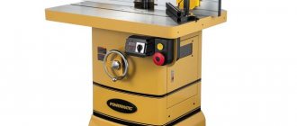
Specifications
Metal boring machines have the following characteristics:
- nominal dimensions of the desktop surface - from 250x450 mm to 630x1100 mm;
- equipment weight - from 1500 kg to 7800 kg;
- minimum boring diameter - from 12 mm;
- the ability to process holes up to 250 mm in diameter;
- part weight - up to 600 kg;
- spindle speed - from 50 to 3000 rpm;
- rated power of the drive motor is from 2 kW to 10 kW.
Varieties
There are two types of jig boring machines according to the type of design:
- Single post. The workpiece in the equipment is fixed on a work table, which moves horizontally in two directions. In this case, the cutting tool is installed in the spindle and moves vertically.
- Two-post. Like its analogue, it has a table with the ability to fasten the workpiece being processed; it moves only in the longitudinal direction. The traverse used in the design has guides for moving the spindle with the tool horizontally and vertically.
According to machine automation there are:
- installed indicators, the ability to set coordinates for processing;
- application of numerical control;
- device for automatic replacement of cutting tools depending on processing conditions;
- the ability to synchronize with the program control unit of the desktop, where the workpiece is fixed.
The dimensions of the equipment depend on the spindle diameter.
Single-column jig boring machine (Photo: Instagram / rage_83)
Application area
Multi-axis machines are in demand from almost any manufacturer of metal products, furniture, plastics, and unique products. The largest number of coordinate systems are found in the automobile and aircraft industries, and the space industry. Such machines can also be seen at sheet material cutting sites.
Vertical multi-axis centers are mobile and can be easily installed on a flat surface in a new location. Manufacturers provide the possibility of upgrading equipment by adding axes; accordingly, the memory and the number of inputs on interface boards have to be increased. From a 3-axis center, 5 or 6-axis systems can be easily achieved.
Selection principle
When purchasing equipment, you should consider the following parameters:
- permissible size range of processed parts;
- machine weight;
- range of internal holes;
- the number of revolutions of the spindle with the tool per minute;
- size, weight of the workpiece;
- power readings of drive motors in all directions of movement of equipment elements.
Advantages and disadvantages
Advantages:
- increased accuracy of workpiece processing in contrast to analogues;
- increasing machine productivity when using a CNC unit;
- use in industry with the possibility of installing equipment in serial production lines;
- protection of the work area;
- obtaining holes of complex shapes using program coordinates;
- small sizes;
- in industry, this device can replace several machines.
Flaws:
- high price;
- complex repair and maintenance of jig boring machines, which requires the involvement of trained personnel.
High-precision equipment (Photo: Instagram / stan.samara)
Manufacturers and cost
Several companies produce this equipment, including:
- CJSC "Stan-Samara" Founded in 1991, the company simultaneously produces grinding equipment.
- JSC MZKRS. Located in Moscow, founded in 1942.
- Foreign model Newall. A special feature of the equipment produced is the table dimensions of 380x530 mm.
- WKV and also WHN.
When purchasing jig boring machines, the consumer must be prepared for the costs. The cost of equipment depends on technical parameters and varies from 150,000 rubles to 1,500,000 rubles.
Complete production process
A CNC jig milling machine operates according to a standard algorithm. First, a model of the future part is created on paper or a personal computer. Next comes the transfer of dimensions and outlines through the application into a machine-readable form of vector graphics. The programmer sets the direction of movement of the tool and inserts technological pauses. Selects the type of tool, processing speed, positioning accuracy of rotating axes.
After converting the model into machine codes, the machine is ready to cut the part. But before that, the program should be debugged. First, 3D movements are tested and the resulting result is monitored. Then, at a limited feed, the automation cycle is started without rotating the main unit - the spindle. If everything goes smoothly and without deviation in the trajectory of movement, then they begin cutting the part.
It should be remembered that no CNC machine can be physically protected from the ignorant. At best, manufacturers provide soft safety couplings against mechanical damage. But even such a small breakdown can lead to prolonged equipment downtime. Therefore, all numbers entered into the processing program must be meaningful and calculated. They act in a similar way when adding correctors for tool wear and backlash compensation.
DIY making
When assembling the machine at home, it is recommended to use high-quality materials at hand.
Guide elements
When making it yourself, you can use round bushings and rods. The disadvantage of homemade products may be premature wear. The use of original guides will result in high costs.
The distance between the slide and the working surface is adjusted using screws. Movement along the guides is carried out using a drive system.
Equipment developers recommend using older typewriters because they are made of high quality steel. They should be carefully disassembled, the carriage and guides with all auxiliary elements should be removed. Each carriage is used separately to provide movement in two directions.
Old typewriter (Photo: Instagram / yulekmoto)
Drive unit
To ensure table movement, it is necessary to use an electric motor with a bearing unit. The movement is transmitted using a screw.
Cardan
It is made from a bronze bushing of the required size. A hole is drilled on the motor shaft and tube and secured together using spokes from a bicycle wheel or a needle from bearings. After connecting to the motor shaft, it is recommended to lubricate the joint.
Drive shaft
Rods made of steel that have undergone heat treatment can be used as this element. It is first necessary to cut a thread on the surface of the workpiece. In this case, the standard step is used.
Bronze split nut
This part should be secured to moving parts of the equipment. It is made from a bronze bar in which a hole is first drilled and then threaded. It is recommended to turn the nut completely before use.
Kinematic diagram of horizontal boring machine 2A620
Kinematic diagram of horizontal boring machine 2a620
Drive of the main movement of horizontal boring machines 2A620F1
The spindle and faceplate rotation is driven by a two-stage speed unit with electromagnetic clutches mounted on the spindle head. Kinematic diagrams of the machines are shown in Fig. 14, 15 and in table. 2.
To protect against dynamic impact, the main drive mechanism has an elastic coupling (Fig. 16).
The transmission of motion to the spindle is carried out by two pairs of gears 63, 64 (100) and 65, 66 (69) (Fig. 17, 18, 19). The larger wheel 64 (100) rotates the spindle in the lower speed range with high torques, and the other, smaller wheel 66 (99) rotates the spindle in the upper speed range with lower torques. The movement is transmitted to the faceplate by a pair of wheels 36, 35. To turn on the rotation of the faceplate, there is a special handle.
The axial movement of the spindle, the radial movement of the faceplate support (Fig. 20), the vertical movement of the spindle head and the longitudinal movement of the table are carried out from a common DC electric motor through a gearbox, which is located on the machine bed (Fig. 21).
The distribution of movement in the movement chain of the spindle, spindle head, radial support and table is carried out longitudinally by means of electromagnetic couplings.
The kinematic chain of the radial caliper drive has a planetary mechanism with satellites 26 and 71, which allows the caliper to move during rotation of the faceplate (Fig. 22).
Axial movement of the boring spindle is carried out by ball screws 86 and 84, located in the tail part of the spindle head (Fig. 23).
Vertical movement of the spindle head is carried out by means of a rotating nut located in the gearbox on the spindle head and a stationary ball screw mounted on the stand (Fig. 24).
The machines are equipped with a mechanism to prevent the spindle head from falling when the counterweight cable breaks (Fig. 25).
When the spindle head counterweight is suspended, part 243, connected to the counterweight cable, is in the upper position, compressing the package of disc springs 244. In this case, ball 245, resting against the shoulder of part 243, through a system of levers fixes part 248 mounted in the spindle head gearbox in the upper position.
If the counterweight cable breaks, part 243, under the influence of a package of disc springs 244, will move down, releasing ball 245 and part 248 through the lever system. Part 248, under the influence of spring 249, will move to the lower position and engage with part 247, which secures shaft 246 from rotation. At the same time, the spindle head is securely fixed from falling.
Drive for lateral movement and rotation of the table
Transverse movement of the table and rotation of the table are carried out from a common DC electric motor through a gearbox, which is located at the rear end of the lower sled.
The distribution of movement to the chain of transverse movement and rotation of the table is carried out by means of electromagnetic couplings in the gearbox (Fig. 26).
Kinematics of thread cutting
The machine allows you to cut metric and inch threads (see “Table of replacement gears for thread cutting”).
Thread cutting is carried out by a retractable spindle during its axial movement or by a radial support of the faceplate during longitudinal movement of the table.
For thread cutting, the spindle feed chain is connected to the spindle rotation drive via a guitar with a set of replaceable gears located at the front end of the spindle head.
To cut left-hand threads on the guitar, an idler gear is installed.
To move the faceplate support away from the steering wheel when cutting threads using the table feed, turn on the handle located on the spindle head cover.
Kinematics of the helm
The spindle head has a steering device for manual movement of the spindle, radial support, spindle head and longitudinal movement of the table.
The turret allows for fine movement of the moving body and rapid movement of the retractable spindle.
The steering wheel is turned on using a button from the remote control on the spindle head.
Exploitation
To prevent accidents, the following safety requirements must be observed:
- when replacing tools at height, it is necessary to use fixed platforms;
- installation of the cutting tool should be carried out with the spindle completely stopped;
- bring the cutter to the workpiece at low speed to avoid breakage of the device;
- it is prohibited to approach the spindle at dangerous distances during processing;
- the instrument must be secured with special devices;
- workpieces must be rigidly fixed to the work table.
By observing safety requirements while working on a jig boring machine, accidents are prevented.