Engineers and other technical specialists know very well that each of the parts that make up machines and mechanisms must have strictly defined operational properties. The most important of them include durability, wear resistance, strength, as well as some other parameters. They depend not only on the material the part is made of, but also on many other factors. One of them is surface roughness.
In order to achieve the desired roughness state, the parts undergo finishing and finishing processing . It should be noted that as a result of this technological process, the surface layer, among other things, also acquires the required physical and mechanical properties.
Grinding
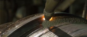
In technology, grinding refers to a method of treating a metal surface that uses an abrasive material. Its cutting parts are abrasive grains.
Finishing operations
Depending on the nature of the surfaces being processed, external, internal and flat grinding are distinguished.
From the point of view of the technological stages of processing the surfaces of parts, grinding is used for both finishing and finishing, as well as for roughing.
Precision Machining
Precision machining (fine turning and boring, diamond turning, fine milling) is characterized by high cutting speeds (100–1,000 m/min), low feeds (0.01–0.15 mm/rev), small depth of cut (0.05 –0.3 mm) with high vibration resistance of the AIDS technological system. Steel workpieces with an intermittent machined surface (the presence of grooves, splines, holes), parts made of high-strength steels and cast iron are processed at cutting speeds of up to 50 m/min (when using tools with a cutting part made of superhard materials, the cutting speed can be increased to 150 m/min) . Precision processing makes it possible to obtain a surface roughness Ra of 0.02–0.63 microns, accuracy of 5–9 grades.
Lapping and finishing
In technology, these operations are finishing , and are used for mechanical processing of parts of various machines, mechanisms, and devices. Their use makes it possible to simultaneously achieve both high accuracy and the required surface roughness. The main tool for lapping and finishing is the so-called lapping. One of its main characteristics is that it is made from a much softer material than the one it is intended to process. It is most often used cast iron of such brands as SCh 20 and SCh 15, various grades of copper, other alloys, and even hard wood. To increase the efficiency of processing , special pastes or abrasive powder mixed with oil are applied to the surface of the parts before it.
The process itself, during which the surface of the lap is saturated with abrasive material, is called caricature. With the help of lapping, operations such as finishing of reamers, measuring tiles, smooth, round and threaded gauges are most often carried out.
Features of artistic metal processing
Artistic types of metal processing include casting, forging and embossing. In the middle of the 20th century, welding was added to them. Each method requires its own tools and devices. With their help, the master either creates a separate work of art, or additionally decorates a utilitarian product, giving it aesthetic content.
Artistic embossing
Embossing is the creation of a relief image on the surface of a metal sheet or the finished product itself, for example, a jug. Embossing is also done on heated metal.
Diamond smoothing
In technology, diamond burnishing is understood as a finishing method in which plastic deformation of the previously processed surface occurs, carried out using a special tool sliding over it.
This finishing treatment is used to either completely eliminate or significantly reduce the irregularities that appeared on them during the previous processing.
One of the main features of this processing method is that in its process the hardness of the surface layer of the part increases. In this case, the workpiece rotates, and after each revolution the tool moves at the feed in the axial direction by a certain amount. Due to the fact that the feed is less than the width of the groove formed by the tool, the marks that are formed from it overlap many times.
The tool smoothes the surface with its spherical working part. It itself is a metal mandrel in which a tip made of synthetic or natural diamond is fixed. The resistance of these crystals to mechanical stress is approximately the same.
Methods of mechanical processing of metals
A large group of methods for machining metals have one thing in common: each of them uses a sharp and hard tool in relation to the workpiece, to which mechanical force is applied. As a result of the interaction, a layer of metal is separated from the part, and its shape changes. The workpiece exceeds the dimensions of the final product by an amount called “allowance”
There are such types of mechanical processing of metals as:
- Turning. The workpiece is fixed in a rotating tooling, and a cutter is brought to it, removing a layer of metal until the dimensions specified by the designer are reached. Used for the production of parts shaped like a body of revolution.
- Drilling. A drill is immersed into a stationary part, which quickly rotates around its axis and is slowly fed towards the workpiece in the longitudinal direction. Used for making round holes.
- Milling. Unlike drilling, where processing is carried out only with the front end of the drill, the side surface of the cutter is also working, and in addition to the vertical direction, the rotating cutter moves both right and left and back and forth. This allows you to create parts of almost any desired shape.
- Planing. The cutter moves back and forth relative to the stationary part, each time removing a longitudinal strip of metal. In some machine models, the cutter is fixed and the part moves. Used to create longitudinal grooves.
- Grinding. The processing is carried out by rotating or performing longitudinal reciprocating movements with an abrasive material that removes thin layers from the surface of the metal. It is used for treating surfaces and preparing them for coating.
Metal grinding
Each operation requires its own special equipment. In the technological process of manufacturing a part, these operations are grouped, alternated and combined to achieve optimal productivity and reduce intra-shop costs.
Honing
In technology, honing is understood as such a procedure as the final finishing of a ground, bored or reamed hole using a hone - a special sliding head, which consists of several sliding abrasive bars.
The hone (honing head) is subject to two movements: reciprocating, along the axis, and rotational, around the axis of the hole being processed (it is relatively slow).
Honing is used to increase dimensional accuracy, reduce shape deviations, reduce surface roughness, and maintain the structure and microhardness of the surface layer of the material.
Technology for preparing surfaces and products for painting
Various chemical methods are used. preparation:
- spraying - with a low-pressure jet, usually a chemical surface preparation unit is used;
- immersion - through a series of sequentially located baths, also an AHP, but different;
- steam jet - manually, using a spray barrel (a high-temperature steam-water mixture under high pressure), degreasing is carried out simultaneously with amorphous phosphating; used on large-sized products.
Standard technology for surface preparation for painting
In cases where special quality of painting is not required, special equipment and standard technology for preparing the surface for painting are used.
There are 4 main stages:
- Cleaning. Includes removal of various types of contamination - brushes, scrapers. Old paint, scale, and rust are removed by heat treatment - first they are heated with a burner flame and then the sludge is removed with brushes and scrapers. It is better to clean large volumes with sandblasters or electric brushes.
- Degreasing. At this stage, severely ingrained rust is removed by wiping the affected areas with a solution of acetic acid (10 percent) or a special detergent for degreasing. Before this, the surface is wiped with a solvent, organic matter and oil stains are removed. Don’t forget: rinse off the acid with water and wait until it dries.
- Apply primer to the entire surface before painting. Additional protection of the cleaned metal from rapidly developing corrosion and leveling of the surface. The final coating acquires the necessary adhesion.
- Grinding. Use fine sandpaper to walk over the dried primer, removing small irregularities and specks. Wipe with a clean cloth.
Sandblasting
Experts from the Radar Powder Coating Center will help you select the necessary equipment.
Super finishing
In technology, superfinishing is understood as a method of finishing surfaces in which their special purity is achieved. It is carried out using oscillating abrasive bars.
Superfinishing is used mainly to process the outer surfaces of various rotating bodies. The essence of this method is the principle of “non-repeating trace”. Its essence is that the same abrasive grain does not pass along the same path twice.
When superfinishing, the main working movement is the oscillation of the head, which, together with the bars, moves along the axis. The stroke of the bars ranges from 2 to 6 millimeters; per minute they make from 200 to 1000 double strokes. In this case, the workpiece is given a rotational movement.
Thermal types of metal processing
Heat treatment of metals is used to improve their physical and mechanical properties. This includes operations such as:
- annealing;
- hardening;
- vacation;
- aging;
- normalization.
Heat treatment of steel
Heat treatment involves heating a part to a certain temperature and then cooling it according to a special program.
Annealing
The workpiece is heated to the plasticity temperature and slowly cooled directly in the furnace.
Annealing reduces the hardness of steel, but significantly increases ductility and malleability.
Annealing
Used before stamping or rolling. During annealing, internal stresses that arise during casting or machining are relieved.
Hardening
When hardening, the workpiece is heated to the plasticity temperature and kept in this state for a certain time, during which the internal structures of the metal are stabilized. Next, the product is quickly cooled in a large amount of water or oil. Hardening significantly increases the hardness of the material and reduces its impact strength, thereby increasing brittleness. Used for structural elements subject to large static and small dynamic loads.
Vacation
Carried out after hardening. The sample is heated to a temperature slightly lower than the quenching temperature and cooled slowly. This allows you to compensate for the excessive fragility that appears after hardening. Used in tool production
Aging
Artificial aging involves stimulating phase transformations in the metal mass. It is carried out with moderate heating to give the material properties that arise during natural aging over a long time.
Polishing
In technology, polishing refers to a finishing operation necessary to obtain a smooth and clean surface of a part. It is produced with special wheels on which a special abrasive powder mixed with lubricant is applied. Polishing is also carried out with soft wheels impregnated with graphite filler.
As a rule, before polishing, parts are sanded with elastic belts or wheels. This is necessary to ensure the required surface cleanliness.
Chemical processing of metals to increase the protective properties of the material
Chemical treatment of metal is the action of special substances on it in order to cause a controlled chemical reaction.
They are performed both as preparatory operations to clean the surface before welding or painting, and as finishing operations to improve the appearance of the product and protect it from corrosion.
Metal galvanizing
Protective coatings are applied using electrochemical treatment using the galvanic method.
How to treat surfaces against coronavirus: recommendations from Rospotrebnadzor
Recommendations regarding how to treat surfaces against coronavirus
Rospotrebnadzor describes the composition and minimum required concentration of active ingredients in products that can fight Covid. These include:
- Tertiary amines 0.05%
- Isopropyl alcohol 70%
- Hydrogen peroxide 3%
- Ethyl alcohol 75%
- Sodium salt of dichloroisocyanuric acid 0.06%
- Calcium (sodium) hypochlorite 0.5%
- Dichloranthine 0.005%
- Quaternary ammonium compounds 0.5%
- Chloramine B 3.0%
- Polymer derivatives of guanidine 0.2%
There is also a list
Russian manufacturers of disinfectants recommended by Rospotrebnadzor.
Whether a particular disinfectant is suitable for eliminating coronavirus pathogens can always be found out from its instructions. The full composition of the product is always indicated there, which can be checked against the list given above, the method of use and the necessary precautions. Instructions can be found on the packaging of the product itself, or online. Now you can easily find official instructions from Rospotrebnadzor for most disinfectants online.
Section 4. Technology of surface treatment of machine parts
Topic 4.1. Machining technologies
This topic explores the following questions:
– methods of processing workpieces on turning machines;
– technological methods for processing holes (drilling, reaming, countersinking, boring, broaching;
– methods of processing flat surfaces;
The main methods of machining by cutting: turning, boring, drilling, milling, planing.
Turning is performed on turning machines and is used primarily for processing the surfaces of parts such as bodies of rotation, which include smooth and stepped shafts, gears, bushings, covers, pulleys, using cutters.
Turning has several varieties: turning, boring, trimming, cutting. Turning – processing of the outer surfaces of workpieces. Boring – processing of internal surfaces of workpieces. Trimming – processing of flat (end) surfaces of workpieces. Cutting – dividing a workpiece into parts.
The turning process is characterized by the rotational movement of the workpiece (the main cutting movement) and the translational movement of the tool - the cutter (the feed movement). The feed movement is carried out parallel to the axis of rotation of the workpiece (longitudinal feed), perpendicular to the axis of rotation of the workpiece (transverse feed).
Schemes of the main types of surface treatment shown in Fig. 4.1 are typical, since they can be implemented on universal lathes, semi-automatic machines, automatic machines and CNC machines. The movement of tools in the feed movement directions depends on the type of machine and they are controlled manually (on universal machines), from cams and copiers (on semi-automatic and automatic machines) or by control commands of the machine’s CNC system program.
On lathes you can turn on centers, in a chuck and on a faceplate; boring; face turning; cutting and trimming; thread cutting; turning cones, shaped surfaces and other types of work using appropriate tools and devices.
External cylindrical surfaces are ground with straight or persistent cutters (Fig. 4.1, a
,
b
).
Smooth shaft blanks are processed by installing them in the centers. The blanks of stepped shafts are turned according to the schemes for dividing the allowance into parts or according to the schemes for dividing the length of the workpiece into parts. External and internal threads (Fig. 4.1, c
) are cut with thread cutters, the shape of the cutting edges of which determines the profile of the threads being cut.
Turning of long flat cones (2 = 8...10°) is carried out by shifting the tailstock body in the transverse direction relative to its base (Fig. 1, d
,
g
) or using a special device - a cone ruler. When machining conical surfaces on CNC machines, the longitudinal and transverse feed movements are automatically summed up.
Through holes on screw-cutting lathes are bored with straight boring tools (Fig. 4.1, d
), deaf - persistent (Fig. 4.1,
f
).
With a transverse feed movement on screw-cutting lathes, the annular grooves are turned (Fig. 4.1, h
) with cutting and slotting cutters.
Rice. 4.1. Schemes of surface treatment on a screw-cutting lathe
Shaped surfaces (fillets) are processed with shaped rod cutters (Fig. 4.1, and
).
Short conical surfaces (chamfers) are obtained with wide cutters, in which the main angle in the plan is equal to half the angle at the apex of the conical surface (Fig. 4.1, j
).
Parts from the workpiece are cut off with cutting tools with an inclined cutting edge, which ensures that the end of the finished part is obtained without a residual burr (Fig. 4.1, l
).
Trimming the ends is performed with special scoring cutters (Fig. 4.1, n
).
On screw-cutting lathes, holes are machined with drills, countersinks and reamers. In this case, processing is carried out by the longitudinal movement of the cutting tool feed (Fig. 4.1, m
)
.
Grinding of external and boring of internal conical surfaces of medium length with any angle of the cone at the apex is carried out with an inclined movement of the feed of the cutters, when turning the upper support (Fig. 4.1,
o
).
According to their purpose turning cutters are divided into pass-through, scoring, boring, cutting-off, shaped, threaded and grooving. Depending on the nature of the operations performed, cutters can be roughing or finishing.
Methods for installing and securing a workpiece processed on a lathe depend on the type of machine, the type of surface being machined, the type of workpiece (shaft, disk, ring, non-round rod, etc.), the ratio of the length of the workpiece to its diameter, the required processing accuracy, and others factors.
External turning of parts with length L <
4
D
is carried out with passing and scoring cutters. Such parts are secured only in the chuck without supporting the free end by the center of the tailstock of the lathe. For fastening, three- and four-jaw chucks are used, screwed onto the spindle. In machine tools for fastening workpieces, pneumatic, hydraulic, centrifugal and other chucks are widely used. A three-jaw self-centering chuck is used to secure symmetrical workpieces, a four-jaw chuck is used to install workpieces of complex and asymmetrical shapes.
For turning external cylindrical surfaces of parts (shafts, axles) with an L/D ratio >
4 usually use longitudinal turning at centers using through cutters.
In this case, centering holes are made on the end surfaces of the workpieces. When processing long parts L/D >
10...12, to protect them from deflection, guide devices are used - open and closed steady rests. To install workpieces such as bushings, rings, cups, conical mandrels, collet mandrels, and elastic mandrels with corrugated bushings are used.
Types of lathes. According to their technological purpose, turning machines are divided into screw-cutting lathes, turret lathes, rotary lathes, multi-cutting machines, single- and multi-spindle automatic machines and semi-automatic machines.
Screw-cutting lathes
They are divided according to the maximum processing diameter, the length of the workpiece being processed, the weight of the machines and their accuracy. Lightweight screw-cutting lathes weighing up to 100 tons are widely used for the manufacture of tools, instrument parts and watches.
Heavy screw-cutting lathes weighing over 400 tons are designed for processing parts with a diameter of 1250 mm or more.
Turning and turret
The machines are designed for the production of similar parts from rods and piece blanks when using multi-tool setup. The turret mounted on the frame allows you to simultaneously secure several different types of tools. The presence of a turret head and a transverse support allows you to simultaneously process several surfaces of the workpiece.
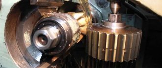
Multi-tool machines
designed for processing workpieces of multi-stage parts with grooves, chamfers and transition surfaces (fillets). A multi-cutting machine is equipped with several cutting tools. If you have a carbon ruler, this machine can be used to grind shaped surfaces.
Vertical lathes
Designed for processing workpieces of heavy parts with a large diameter and a relatively short length. On rotary machines you can turn cylindrical and conical ones, trim ends, cut grooves, drill, countersink, and ream.
Multi-tool machines
designed for processing workpieces of multi-stage parts with grooves, chamfers and transition surfaces (fillets). A multi-cutting machine is equipped with several cutting tools. If you have a carbon ruler, this machine can be used to grind shaped surfaces.
Automatic lathes
are designed for processing rod workpieces, and semi-automatic lathes are designed for processing rod workpieces and piece workpieces.
Technological methods for processing holes (internal surfaces) . In the manufacture of machine parts for various purposes, one encounters the processing of the following types of holes: smooth cylindrical and conical, stepped, shaped, through and blind. Achieving the required accuracy when machining holes is more difficult than when machining external surfaces. The complexity of processing holes is explained by a number of reasons: the rigidity of the tool for processing holes is limited by the size of the latter; chip removal and supply of cutting fluid (coolant) deteriorate; the surface itself is less accessible for viewing and control (including measurement).
Depending on the service purpose of the hole, it is necessary to ensure the following parameters: size tolerance, surface roughness, straightness of the hole axis, correct geometric shape (for example, roundness for cylindrical and conical holes), alignment and concentricity with other cylindrical surfaces and holes, perpendicularity of the hole axis to the end , the distance between the axes of the holes. Often, to ensure the required dimensional characteristics of a part, a hole is selected as a base and processed at the beginning of the technological route.
Drilling is the main technological method of forming holes in the solid material of a workpiece. Drilling can produce both through and blind holes.
The most common method of conventional (shallow) drilling is processing with a twist drill.
. One drill usually drills holes with a diameter of up to 20...30 mm. When processing holes of larger diameter, subsequent drilling, countersinking, boring and broaching are used.
Processing can be carried out by imparting rotation to the tool or the workpiece being processed. The following drilling schemes are used: 1) the tool rotates, an axial feed is imparted to it, the part is stationary; 2) rotation is imparted to the part, and axial feed is imparted to the non-rotating tool; 3) counter rotation of the part and the tool.
A common defect during drilling is the curvature of the hole axis (drill slip). This is especially noticeable when drilling deep holes. The most radical way to eliminate drill slip is to impart rotation to the part and the tool.
When drilling large diameter holes, core drill bits are often used. Depending on the type of processing, drills for deep holes, single-edged, with a coolant supply, feather drills, etc. are also distinguished; These drills are special and are used extremely rarely.
Types of drilling machines. Tabletop drilling machines are produced for drilling holes with a diameter of up to 16 mm; vertical drilling and radial drilling – for drilling holes with a diameter of up to 100 mm. Horizontal drilling machines are designed to produce deep holes using special drills.
In single and small-scale production, vertical drilling machines are used. When processing massive or large-sized workpieces, radial drilling machines are used, in which the spindle with the tool moves relative to the workpiece and can be installed at the required point in the horizontal plane.
Holes on drilling machines are processed with drills, countersinks, reamers and taps.
A blade tool can be used for drilling, countersinking, reaming, boring, and broaching.
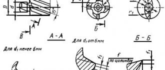
Reaming
(Fig. 4.2,
b
) - the process of increasing the diameter of a previously drilled hole with a larger diameter drill in order to improve their accuracy and quality (up to 9th grade and
Ra
= 2.5 microns).
Countersinking
(Fig. 4.2,
c
) is used for pre-processing of cast and stamped holes to improve the accuracy and surface quality (μm) of a hole pre-processed (by drilling) with a multi-blade cutting tool - a countersink.
Deployment
(Fig. 4.2,
d
,
e
) – final processing of a cylindrical or conical hole with a reamer (usually after countersinking) in order to obtain high accuracy and low roughness of the machined surface (
Ra
= 0.32 µm).
Rice. 4.2. Basic drilling patterns
Countering
(Figure 4.2,
f
) process the end support planes for the heads of bolts, screws and nuts. The perpendicularity of the machined end surface to the main hole is ensured by the counterbore guide cylinder.
Countersinking
cylindrical or conical recesses are obtained in the existing holes for the heads of screws, bolts, rivets and other parts.
In Fig. 4.2, g
,
h
shows countersinking of a cylindrical recess with a cylindrical countersink (countersink) and a conical recess with a conical countersink.
Threading
– obtaining a helical groove on the inner cylindrical surface using a tap (Fig. 4.2,
and
).
Holes with complex profiles are processed using a combined cutting tool. In Fig. 4.2, k
shows a combined countersink for processing two surfaces: cylindrical and conical.
Boring holes . Boring is turning of existing holes with boring cutters in order to improve their accuracy and quality (up to 2nd accuracy grade and Ra
= 0.32 µm).
Boring is carried out according to the same scheme as turning external cylindrical surfaces. The rotational movement here is the main cutting movement, and the rectilinear translational movement along the axis of the hole being machined is the feed movement.
When processing internal cylindrical surfaces of large diameters, boring is carried out on lathes. In this case, the part is mounted in a three-jaw chuck and supported by a steady rest. Both through and blind holes are processed using boring cutters. To improve the accuracy and quality of machining internal holes, more rigid boring bars are used. A round boring bar is installed in the guide bushings of a special device.
Types of boring machines. Boring machines are divided into horizontal boring, jig boring, diamond boring and special. The most widely used are horizontal boring machines (HSB), which most often process blanks of large and medium-sized body parts. GDS mainly processes holes in small-scale and medium-scale production. GDS have wide versatility and can be used to perform various types of processing. The workpieces are installed and secured on the GDS table (plate) or in special devices. Cutting tools intended for performing operations are installed and secured by means of an auxiliary tool (mandrel, boring bar, tool holder) in the machine spindle, radial support of the faceplate or special boring devices.
Jig boring machines have found the greatest application in tool production for the manufacture of stamps, molds, templates, and copiers. On diamond boring machines, holes are finally machined with diamond and carbide cutters in small-sized body workpieces. Diamond boring machines are widely used for boring holes in cylinder blocks and liners of tractor, automobile and motorcycle engines.
Broaching of internal surfaces is a high-performance and accurate method of processing by cutting through holes, ensuring the production of machined surfaces of the 6th...9th accuracy grade with a roughness up to Ra
= 0.63 µm. It is used, as a rule, for finishing the internal surfaces of any transverse profile (cylindrical, square, polyhedral, spline holes and keyways). In this case, the profile of the machined surface in the cross section is determined by the sharpening profile of the broach teeth - a special cutting tool that makes a translational movement (the main cutting movement).
There is no feed movement during broaching as an independent movement of the tool or workpiece.
A broach for processing internal holes is a multi-edged cutting tool that has a large length despite relatively small transverse dimensions. On the cutting part (roughing and finishing) there are cutting teeth located one after the other. The outer size of each subsequent broach tooth is larger than the previous one. In addition to the cutting part, the broach has a calibrating part that cuts off the allowance formed as a result of the end of the action of elastic deformations; front and back; a guide cone for centering the broach in the hole being processed; a neck and a locking part designed to secure the broach in the chuck of the broaching machine. Broaches can be either standard or non-standard.
During the cutting process, the broach is literally pulled with force through a stationary workpiece.
Distinctive features of the cutting process when broaching is the ability to carry out combined processing (roughing, finishing, calibrating and finishing-hardening) in one pass.