What is plane roughness by type of processing
When manufacturing the required part, in accordance with technical drawings and sketches, various types of processing are used. The initial workpiece is subjected to heating, drilling, cutting and other technological operations.
Each type of processing of a product leaves a certain pattern on its surface in the form of small shagreen, gouges, microscopic cracks and scratches. All these consequences are displayed in the form of roughness on the processed surface of the product.
According to the type of technological impact, a certain class of plane roughness arises. All types and dimensions of this phenomenon are presented in more detail in GOST 2789-73 “ Surface Roughness ” .
The standard contains detailed information with illustrations of roughness. Some types of technical influence leave changes on the surface of the material that are not noticeable to the eye. These roughnesses are studied under a microscope.
The main indicators of shagreen include:
- The height of the treated surface, measured in 10 points;
- Average number of plane deviations;
- Average pitch of irregularities;
- The highest point of the plane after processing;
- Profile reference length.
Finishing metal grinding and polishing of the product maximally levels the surface of the processing, but internal changes at the molecular level in the material leave certain consequences in the form of microscopic shagreen.
The influence of roughness on the performance of parts
As mentioned earlier, in the process of giving a metal sheet the desired configuration, roughness remains at the impact sites - small depressions and ridges that affect the determination of the metal processing class. They can arise due to the unevenness of the cutting tool or vibrations that occur during work, remain as an imprint of unevenness on the stamp or mold itself, etc.
The presence of roughness in a part installed in a machine or other unit can lead to:
- incorrect mating of elements due to crushing of the material or accelerated wear of the protrusions of the part;
- decrease in joint strength, defects when applying paint and varnish and galvanic coatings;
- incorrect results of geometric measurements of an element;
- reducing the rigidity of butt joints;
- destruction of seals mated to shaft surfaces;
- reducing the fatigue strength of the element due to stress concentration in roughness;
- accelerated oxidation and deterioration of metal, etc.
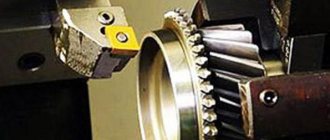
Roughness during turning
This indicator is displayed as a set of small steps of the base length of the processed plane and its irregularities. Modern turning equipment ensures the highest possible quality of parts production. Shagreen during turning is a value that is calculated at the design stage of the future product.
In many machines, by default, the required tolerances of shagreen on the plane are set, which greatly facilitates the task of personnel and increases production volumes. The main factor here is the exact shagreen indicators for the specific material from which the future part is composed.
Basic designations
The roughness of the surface under study is measured over tolerably small areas, and therefore the baselines are selected taking into account the parameter of reducing the influence of the wave-like state of the surface on changes in height parameters.
Irregularities on most surfaces arise due to the resulting deformations of the top layer of material during processing using various technologies. The outline of the profile is obtained during an examination using a diamond needle, and the imprint is recorded on a profilogram. The main parameters characterizing surface roughness have a specific letter designation, used in documentation, drawings and obtained when measuring parts (Rz, Ra, Rmax, Sm, Si, Tp).
To measure surface roughness, several defining parameters are used:
- Ra- denotes the value of the profile under study with possible deviation (arithmetic mean) and is measured in microns;
- Rz – denotes the height of the measured irregularities determined by 10 main points in microns;
- Rmax is the maximum permissible value of the height parameter.
Surface roughness designation
The step parameters Sm and Si and the reference length of the profile under study tp are also used. These parameters are indicated if it is necessary to take into account the operating conditions of the parts. In most cases, the universal indicator Ra is used for measurements, which gives the most complete characteristic taking into account all points of the profile. The value of the average height Rz is used when difficulties arise in determining Ra using instruments. Such characteristics affect the resistance and vibration resistance, as well as the electrical conductivity of materials.
The definition values of Ra and Rz are indicated in special tables and, if necessary, can be used when carrying out the necessary calculations. Typically, the determinant Ra is indicated without a numerical symbol; other indicators have the required symbol. According to current regulations (GOST), there is a scale that gives the values of surface roughness of various parts, which have a detailed breakdown into 14 special classes.
There is a direct relationship that determines the characteristics of the surface being processed; the higher the class indicator, the less important the height of the measured surface is and the better the quality of processing.
How is plane roughness measured by type of processing?
Even the most modern technologies for working with shagreen surfaces cannot provide a perfectly smooth surface. In this regard, there are always certain deviations from the specified design drawing of the part. They can be macro or microgeometric in nature.
It is customary to distinguish 3 main types of this indicator:
- Initial shagreen (occurs when the product comes into contact with various abrasive attachments);
- Operational (manifests itself as a result of friction and natural wear during processing);
- Equilibrium (the result of friction under stationary processing conditions).
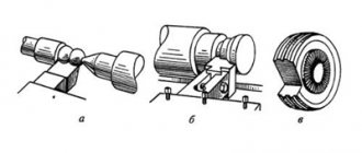
Shagreen is measured comprehensively or element by element. The second option is the most accurate, but also much more labor-intensive. In practice, the following 3 main measurement methods are used:
- Using a probe. The top layer is measured with a specialized profilometer sensor equipped with a small diamond needle. At its end there is a sensitive head, which provides signals to the device when monitoring the plane. The operation of the device resembles an echo sounder.
Profilometers are: electronic, inductive and piezoelectric. More advanced devices called profilographs are capable of recording all the measurements obtained for further study by specialist technologists.
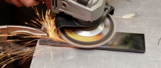
- Optical method. It is a non-contact measuring option for shagreen, consisting of several calculation options.
Using a raster. A thin glass plate coated with a special raster (reminiscent of a grid) is fixed onto the processed plane. Next, light rays are applied at a certain angle and the raster lines coincide with the shagreen surface, repeating its relief.
With the help of shadow. A specialized ruler with a beveled edge is placed on the element being studied. It is through it that the supplied light beam passes. The shadow that appears in this case thoroughly displays the relief of the plane of the part, the results of which are subsequently studied under a microscope.
- Microinterference method. The plane is measured using curved stripes produced by an interferometer device. And its results are subsequently studied under a microscope and an accurate picture of the surface is obtained.
The roughness of the top layer affects the further use of the resulting parts. The quality of welding of such elements, painting and other further operations depends on its coefficient.
Surface roughness and its influence on the operation of machine parts
During the process of forming parts, roughness appears on their surface - a series of alternating protrusions and depressions of relatively small sizes.
Roughness can be a mark from a cutter or other cutting tool, a copy of the irregularities of molds or dies, and can appear as a result of vibrations that occur during cutting, as well as as a result of other factors.
The influence of roughness on the operation of machine parts is diverse:
- surface roughness can disrupt the nature of the mating of parts due to crushing or intense wear of the profile protrusions;
- in butt joints, due to significant roughness, the rigidity of the joints decreases;
- the roughness of the surface of the shafts destroys various types of seals in contact with them;
- irregularities, being stress concentrators, reduce the fatigue strength of parts;
- roughness affects the tightness of connections and the quality of galvanic and paint coatings;
- roughness affects the accuracy of measuring parts;
- metal corrosion occurs and spreads faster on roughly processed surfaces, etc.
Roughness table
The initial roughness is a consequence of the technological processing of the surface of the material. For a wide class of surfaces, the horizontal pitch of irregularities ranges from 1 to 1000 µm, and the height - from 0.01 to 10 µm. As a result of friction and wear, the parameters of the initial roughness, as a rule, change, and operational roughness is formed. The operational roughness, reproduced under stationary friction conditions, is called equilibrium roughness.
| Class | 1 | 2 | 3 | 4 | 5 | 6 | 7 | 8 | 9 | 10 | 11 | 12 | 13 | 14 |
| The cells above indicate roughness classes for comparison with the new standard | ||||||||||||||
| Ra | 100 | 50 | 25 | 12.5 | 6.3 | 3.2 | 1.6 | 0.8 | 0.4 | 0.2 | 0.1 | 0.08 | 0.025 | 0.01 |
| Rz | 400 | 200 | 100 | 50 | 25 | 12.5 | 6.3 | 3.2 | 1.6 | 0.8 | 0.4 | 0.2 | 0.1 | 0.05 |
| Sandblasting | Rz400 | |||||||||||||
| Forging in dies | Rz400 | Rz200 | Rz100 | |||||||||||
| Sawing | Rz400 | |||||||||||||
| Drilling | Rz100 | Rz50 | Rz25 | |||||||||||
| Rough countersinking | Rz100 | Rz50 | Rz25 | |||||||||||
| Finish countersinking | Rz50 | Rz25 | 3.2 | 1.6 | ||||||||||
| Deployment is normal | 3.2 | 1.6 | 0.8 | |||||||||||
| Deployment is precise | 1.6 | 0.8 | 0.4 | |||||||||||
| Deployment is subtle | 0.8 | 0.4 | 0.2 | |||||||||||
| Reaching out | Rz25 | 3.2 | 1.6 | 0.8 | 0.4 | |||||||||
| Rough turning | Rz400 | Rz200 | Rz100 | Rz50 | ||||||||||
| Finish turning | Rz100 | Rz50 | Rz25 | 3.2 | 1.6 | 0.8 | ||||||||
| Fine turning | 3.2 | 1.6 | 0.8 | 0.4 | ||||||||||
| Preliminary planing | Rz400 | Rz200 | Rz100 | Rz50 | ||||||||||
| Finish planing | Rz100 | Rz50 | Rz25 | 3.2 | 1.6 | |||||||||
| Fine planing | 1.6 | 0.8 | ||||||||||||
| Pre-milling | Rz200 | Rz100 | Rz50 | Rz25 | ||||||||||
| Finish milling | Rz25 | 3.2 | 1.6 | |||||||||||
| Milling fine | 3.2 | 1.6 | 0.8 | |||||||||||
| Pre-grinding | Rz25 | 3.2 | 1.6 | |||||||||||
| Finish grinding | 1.6 | 0.8 | 0.4 | |||||||||||
| Sanding fine | 0.4 | 0.2 | ||||||||||||
| Sanding - finishing | 0.1 | 0.08 | Rz0.1 | Rz0.05 | ||||||||||
| Rough grinding | 0.8 | 0.4 | ||||||||||||
| Lapping average | 0.4 | 0.2 | 0.1 | |||||||||||
| Fine lapping | 0.1 | 0.08 | Rz0.1 | Rz0.05 | ||||||||||
| Honing is normal | 1.6 | 0.8 | 0.4 | 0.2 | ||||||||||
| Mirror honing | 0.4 | 0.2 | 0.1 | 0.08 | ||||||||||
| Scraping | 3.2 | 1.6 | 0.8 | |||||||||||
| Rolling | Rz50 | Rz25 | 3.2 | 1.6 | 0.8 | |||||||||
| Chill casting | Rz400 | Rz200 | Rz100 | Rz50 | ||||||||||
| Injection molding | Rz400 | Rz200 | Rz100 | Rz50 | Rz25 | 3.2 | ||||||||
| Precision casting | Rz50 | Rz25 | 3.2 | 1.6 | ||||||||||
| Plastic molding, precision | Rz25 | 3.2 | 1.6 | 0.8 | 0.4 | 0.2 | 0.1 |
What types of surfaces exist
To ensure interchangeability and unification of production, roughness parameters are combined into classes. There are 14 varieties of them in total. Each class is assigned a specific Ra and Rz value. The most accurate class is the fourteenth, the roughest is the first. For this reason, surfaces have also been classified. The following types are found in production:
- Mounting surfaces that are motionless relative to each other and are not subject to tightness requirements. For them, the Ra value is 2.5-20 µm.
- Working surfaces that move relative to each other. This includes piston-cylinder connections, which can often be found in a variety of engines and pumps. Ra for them is 0.16-2.5 microns.
- Bounding and connecting surfaces. This refers to the elements necessary for fastening and assembly. These are all kinds of cases, clamps and other mechanisms. Ra for them ranges from 2.5-20 microns.
- Special surfaces. Here we mainly refer to the controls. The processing of such surfaces is extremely high with their Ra value of 0.63-0.08 µm.
Control methods
To control surface roughness, two methods are used:
- qualitative;
- quantitative.
When carrying out qualitative control, a comparative analysis of the surface of the working test and standard samples is carried out by visual inspection and by touch. To carry out the research, special sets of surface samples are produced that have routine processing in accordance with GOST 9378-75. Each sample is marked indicating the Ra index and the method of influencing the surface layer of the material (grinding, turning, milling, etc.). Using visual inspection, it is possible to fairly accurately characterize the surface layer with characteristics Ra = 0.6-0.8 µm and higher.
Surface roughness samples
Quantitative surface control is carried out using instruments using different technologies:
- profilometer;
- profiler;
- double microscope.