The wafer check valve is designed to protect pipelines from changes in pressure and temperature. The devices are produced as spring, single- and double-leaf, and rotary. Alloys of steel, bronze and aluminum are used in production. The products are used in housing and communal services, chemical and oil production industries.
Wafer check valve
Why are wafer valves needed?
A check valve is a type of shut-off valve. Its task is to organize the flow of the medium in one direction and prevent reverse flow. Operating a pipeline without check valves can cause breakdowns and cause an emergency. Another function of the equipment is to protect the pipeline system from water hammer.
The modules require several types of attachment to the pipe:
- welded,
- flanged,
- wafer,
- coupling
| It is important to know! Wafer-type valves are fastened by clamping between pipeline flanges. The device automatically starts when the mixture is transported through pipes. |
Tips for choosing
In practice, in everyday life we may encounter the installation of a coupling check valve (clutch valve) after the water meter and at the inlet of the heating system. Choosing a shutter for a meter makes virtually no sense - they are sold everywhere and produced in every region. The technology and design are also the same everywhere. Material: brass. The main thing is to buy it in a store, with a receipt, a guarantee, and inspect it visually. The most important thing is that the nominal diameter coincides with the diameter of the water meter!
Work on the heating system input must be carried out by utility specialists. But it is likely that under certain conditions the residents of the house will still have to buy and select components for the input unit. The most important thing is to purchase from a construction hypermarket, with a guarantee, the required nominal diameter. The choice of materials is very important: the ideal, but expensive option is stainless steel or brass.
The best option in terms of price/quality ratio - structural steel with a stainless steel working body - also works well and lasts a long time.
Reed valves and flapper models
The check valve flaps are held closed by springs. The change in position causes the direction of flow. So, if the transported masses move along a vector, they exert pressure on the valve flaps and it opens. When the reverse current flows, the contents of the pipe act on the spring-loaded flap, and the gap closes.
There are flap valves and reed valves. The second group has two doors that work synchronously. Thanks to the fastening of the valves at two points, the valve is characterized by greater stability and reliably serves on pipelines of large cross-sections (up to 400 mm) and under pressure.
In the Smartex Group product range you will find wafer check valves of the following diameters:
- DN 50;
- DN 65;
- DN 80;
- DN 100;
- DN 125;
- DN 150;
- DN 200;
- DN 250;
- DN 300;
- DN 400.
Application and main functions
The fittings are designed to block the possibility of changing the direction of liquid or gas in a pipe during a drop in pressure, emergency situations, or as a result of water hammer. In household communications, these shut-off devices are used in ventilation systems, heating communications, and when installing sewage drains.
Preventing backflows in pipeline services is critical to the efficient and safe transport of liquids or gases.
The formation of reverse flow is fraught with failure of pipelines and the creation of emergency situations with serious consequences. The most harmless example that can be given is the formation of a backflow in a sewer pipe, when the discharged waste suddenly rushes back and begins to flow from all technological openings for its discharge.
Wafer check valves are installed without threads, using rubber gaskets as an insulating seal.
Wafer check valve is used:
- To prevent the possibility of a change in flow direction as a result of a pressure difference in the pipe, for example, when turning off the forced transport pump.
- To equalize the flow force. Here, shut-off valves of this type play the role of a control gateway during water hammer, preventing emergency situations.
Note! The wafer check valve operates automatically and does not require additional maintenance after installation.
Equipment characteristics
- Diameter from 50 to 400 mm.
- Connection method (wafer, flange, coupling, welding).
- Operating temperature (from 0 to 80 degrees).
- Working pressure (limit 20.7 bar).
- Capacity (depends on the diameter of the valves, measured in m3/h at a pressure of 1 bar).
Depending on the protective coating, the valves can be used on routes with different media. They are designed for installation on pipelines moving water and compressed air.
How to install it yourself
At the time of design, the risk of flooding should already be included in the system, so during this period it is necessary to work out the installation of the valve. Installation takes place in several stages.
Installation of a check valve can be done both on an external system and on an internal one.
The first stage is choosing an installation location
The location for installing the throttle must be easily accessible. The equipment must not be installed in the wall or floor, covered or cluttered.
Each device has a cover for cleaning and repair, so access to it is required at all times. If the sewerage system runs in the floor or concrete base, the locking mechanism is mounted in the pipe, and its upper part remains on the surface.
If the depth of the gasket is large and the headband is out of sight, we make a removable cover in the floor for inspection.
The second stage is choosing a device
Locks are classified differently, some are installed outdoors, in a well, others can only be installed indoors. It is necessary to choose the most suitable one for the installation conditions. If there is an error at this point, the shutter may subsequently collapse or crack.
Tools:
- Grinder with cutting disc.
- A sharp, hard knife for chamfering.
- Oil, lubrication paste.
- Hammer and flat board.
- At the installation site, we clear the work area.
- We measure the length of the device so that it fits into the prepared space.
- Lubricate the end of the pipe generously with motor oil or plumbing paste.
- The O-ring should also be treated.
- Before inserting the firecracker into the pipe, having made the socket, we will turn the device several times (if possible).
- With a little effort, but sharply we stick the pipe into the throttle.
- Then we check to see if the rubber band in the device has pulled up.
- On the reverse side we continue assembling the sewerage system.
It is not always possible to install a throttle during the initial installation of the pipeline. This can be done in the current system.
- Having chosen a place, use a grinder to carefully cut out a piece of pipe. It is advisable to choose a place closer to the socket so that the piece can be removed.
- We make a piece of pipe slightly larger than the device itself. In order not to disassemble the entire thread, we will need a channel with a compensatory socket.
- We insert the compensator into the pipe, and the valve from the other edge.
- We insert the assembly onto the pipeline first from the side of the compensator, moving it until it stops, then, pushing it out of the socket, insert the valve on the other side.
How to chamfer a plastic or PVC pipe
The end, if it is not fixed in the system, is pulled out and pressed between the legs or armpit so that the cut is in front of the eyes. Using a sharp knife, we begin to cut the edge in a circle. The result is a chamfer, a cone. We also remove all burrs in the cut areas.
How to place it at the outlet of a plumbing fixture
To install it to the toilet, you will need an external device without a stable housing, inside which the clapper moves. Instead, a cuff is placed on the back of the toilet, with a hard membrane attached to the end. The shutter is of a conical type. A serial connection allows you to insert the device inside the socket, where the plate will work. We coat each joint with oil or plumbing paste for better connection.
Scope of application
The valves are designed for installation on horizontal and vertical sections of the pipeline. Due to their functionality and corrosion resistance, they are used in a wide variety of areas:
- fire equipment;
- heat and water supply systems;
- chemical industry;
- in production for supplying water and other liquids.
The location of check valves in the pipeline system is clearly regulated and specified in installation standards. In engineering systems, shut-off valves are installed:
- on the pressure line of each pump that is connected in parallel;
- at a heating point in the area between the supply and return pipelines;
- after the water meter.
Expert advice
When installing a water metering unit, especially in a steel water supply system, it may be inconvenient to install - there will not be enough space to screw on the union nut at the last moment. In this case, it is worth supplementing the metering unit with another union nut - an “American” one on the valve side (of the “nut-fitting” type).
Do not be afraid to install a check valve on the metering unit yourself. This is quite affordable for the novice home DIYer.
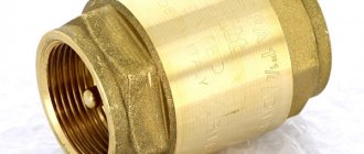
Materials
Wafer check valves are made of cast iron and painted red. The outside and inside of the product has an anti-corrosion coating made of thermosetting epoxy resin.
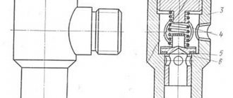
The valve consists of the following elements:
- body (cast iron 65-45-12);
- leaf valve (cast iron 65-45-12);
- stem (420 stainless steel);
- spring (304 stainless steel);
- seals (EPDM).
Certificates and other permits
The modules were developed by Rapidrop Global Ltd, whose production facilities are located in the UK. The company has been operating in the global market for more than 20 years and is a leader in the segment of equipment for water fire extinguishing systems. Valves are UL listed, Gost certified, anti-corrosion coating meets ANSI/AWWA C550 standards.
Installation rules
Installation is carried out on discontinuous sections of the pipeline between two flanges. To create a tight connection, gaskets must be used. The sealing element must be compatible with the working environment.
| It is important to know! Installation on a horizontal pipeline requires the axis of the valve flaps to be positioned strictly vertically. On a vertical pipeline, the axis can be located in any direction. |
When performing installation, the following regulations must be observed:
- installation must be carried out by persons with appropriate qualifications who have studied the safety regulations;
- the selected article must correspond to the operating parameters of the pipeline;
- before installation, the valve is inspected for compliance with the flange diameters;
- the module undergoes a visual inspection, the integrity of the valve seat and the mobility of the valves are assessed;
- counter flanges are cleaned of dust and debris.
During installation, the flanges are positioned plane-parallel, ensuring free placement of the valve with sealing elements. The reinforcement is fastened with bolts. The connection is checked for alignment. The studs are gradually tightened, the procedure is carried out evenly in 3-4 passes in a crisscross pattern, sequentially.
To prevent emergency situations, equipment requires periodic inspection. The regularity of inspections depends on the standards adopted in production and the characteristics of equipment operation.
Main varieties
If we review the most popular check valve devices, we should start with rotary models, in particular with the DN150 wafer valve. DU150, like other models, allows the flow of the working medium through itself in only one direction. If the direction of movement of the working fluid flow changes, the valve is automatically blocked and its shutter is closed.
Among the check valves belonging to the class of rotary valves, there are:
- simple;
- unstressed.
The locking element of rotary-type check valves is a spool, which allows them to be used even when working with heavily contaminated working media. In addition, the design features of such valve devices make it possible to use them for pipelines of even significant diameter (from fifty to one hundred and fifty millimeters).
Rotary check valve 19CH21BR
Rotary check valves, the structural elements of which are made of brass, are used to equip heating systems, as well as water and heat supply systems. The design of such valves, which operate primarily with a liquid working medium, includes a mesh that acts as a filter element.
Depending on their design, rotary check valves can be one of three types:
- coupling;
- flanged;
- wafer
Wafer devices, in turn, are divided into check valves of the following types:
- reverse wafer valve made of stainless steel;
- double-leaf type wafer check valve;
- check wafer valves made of cast iron.
Steel rotary check valves with flanges for welding
Popular models of check valve wafer devices, for the manufacture of which steel alloys are used, are also DN25, 32, 50, 80, 110. The most significant advantages of these valve devices are compact dimensions and affordable cost. Meanwhile, when using wafer valves in a pipeline, a significant loss of pressure of the transported working medium occurs.
Among the many check valves offered by modern manufacturers, we should highlight the DU150 flange lift valve and the DU100 model, which are installed and successfully used on pipelines for various purposes. Mention should also be made of a brass wafer check valve with two flaps mounted on the same axis. Valve devices of this type, characterized by unpretentious installation, are used to equip pipelines whose diameter is in the range of 50–80 mm.
Based on the material of manufacture, flanged valve devices are divided into the following types of products:
- wafer-type steel check valve with protective mesh;
- cast iron check valve, also equipped with a mesh that acts as a filter element.
Flanged check valve with safety net
Valves made of cast iron or steel alloy are large in size and weight, which somewhat limits their scope of application.
In order not to significantly lose pressure in the working medium transported through the pipeline, it can be equipped with spring-type check valves, which can be made of either cast iron or brass alloy. Flanged check valves are also equipped with a spring, the most popular models of which include DN50, 80, 110. Their great advantage is that they can be installed in both horizontal and vertical positions. In addition, wafer spring check valves can successfully withstand such phenomena as water hammer.
Closing of the valve in check valves that are not equipped with a spring is ensured by the force of gravity that the valve itself has. Their installation can be carried out both horizontally and vertically, but only if the flow of the working medium transported through a vertical pipeline is directed from bottom to top.
Today, ventilation systems are also equipped with reverse air seals, which is necessary in order to prevent contaminated air from entering back into the ventilated room. Such devices can be found in ventilation systems serving not only industrial premises, but also office and domestic premises (kitchens, sanitary facilities, etc.). In addition, ventilation systems installed in public buildings – shopping and entertainment centers, shopping malls, etc. – are equipped with check valves.
The ventilation check valve is used to prevent air flow when the fan is turned off.
The design of check valves installed in ventilation systems is formed by a rotating axis on which special blades are fixed. These blades can cut off the air flow due to a special spring or gravity.
Another type of such devices is a poppet (or disk) check valve, the closing element of which is a disk located in a seat with a sealing element. The shut-off element in the disc check valve is fixed on a rod that can move freely in the device body. The disc type check valve can be wafer or coupling. It is used to equip both pipelines through which gaseous working media are transported and ventilation systems.
Advantages of valves
- Simple on-line installation.
- Equipment reliability.
- Durability of work.
- Minor loss of pressure.
- Relatively low price.
- Compact dimensions.
- Light weight.
- High maintainability.
- Minimum maintenance requirements.
When choosing equipment, it is necessary to take into account the diameter of the water supply, the working environment, the temperature range and the planned pressure. If you are in doubt about the selection of equipment, contact our consultants. They will help you complete your order and advise on current technical specifications.
Advantages and disadvantages
Advantages of the reverse wafer device:
- small weight;
- compact dimensions of the shut-off elements, allowing the device to be secured to different sections of the pipeline;
- efficient operation in systems with contaminated environments;
- Possibility of installation on pipes with large diameters;
- low hydraulic resistance;
- anti-corrosion treatment;
- resistance to changes in temperature conditions;
- low-cost installation, cheap maintenance and repairs;
- versatility, durability, reliability of the design solution.
The disadvantage of the control device is the loss of pressure intensity when passing through the valve due to the presence of an axis and flaps or disk. When making calculations, it is necessary to take into account changes in operating pressure indicators. Disc elements reduce the flow rate of the medium faster than flap elements.
Check valves only regulate the flow of the working medium, without replacing standard valves for reliably shutting off the flow.
If operational characteristics are violated (temperature changes, flow is blocked by contaminants), the wafer valve allows liquid or gas to pass through.
What is
Pipeline or shut-off valves are one of the most important and necessary mechanisms that are responsible for the correct operation of the entire system. The correctness of its operation and the uninterrupted flow of the transported flow will depend on the correct selection and subsequent installation. If you do not pay enough attention to this point or simply save money by choosing a little-known supplier or an obvious fake, a breakdown will immediately follow after installation, which can render other equally expensive equipment unusable and stop the line. To avoid such situations, you should give preference only to high-quality units and buy them from the manufacturer or trusted suppliers.
HIGH TECH
Check valve bodies are also made of bronze or brass for water supply with a diameter of 10 to 100 mm, these are mainly sleeve valves, and welding versions are not made from these materials. Steel bodies are more expensive than cast iron or brass, but they have a number of other advantages; they can be made in a welded design; alloy steel allows the body to be used at a temperature of -60 degrees C. Stainless steels are used for valves intended for aggressive environments or for increased requirements - work with high and low temperatures (-60...+480 degrees C), high pressures (400 kgf/cm2), they are even more expensive.
In addition, the sealing surfaces of the body and flaps can be additionally coated with an alloy of increased resistance (for example, titanium nitride); steel flaps can be coated with a corrosion-resistant material (for example, Steel 20X13). Galvanized steels are also used.
The correct choice of materials will ensure a long valve life of more than 30 years without the need for additional maintenance.
Check valve seal material
The main materials for valve seals are: stainless steel, bronze, brass, rubber, paronite. O-rings can also be overlaid with a stainless alloy.
The valve with soft rubber seals provides tightness class A, but has some limitations; they can be used in a limited temperature range. The following rubber materials are used:
1. Nitrile butadiene rubber NBR : operating temperature –10…+80°С. Oil and petrol resistant rubber. Works well with cold water, petroleum products, natural gas, technical oils, air with added oil (maximum permissible temperature -20...+90 degrees C).
2. Ethylene-propylene rubber EPDM : –10…+110°С. Works well with cold and hot water, sea water, alkalis, alcohols, acids with a concentration of up to 10%, salts of acids, dry air without oil impurities (maximum permissible temperature -30...+150 degrees C).
3. Heat-resistant polymer of ethylene and propylene EPDM HT : -15C...+130 degrees C. Works well with the same environments as EPDM (maximum permissible temperature -30...+150 degrees C).
4. Fluoroplastic (PTFE) : -10…+150 degrees C. Temperature-resistant polymer. Works well with hot and cold water, technical oils, hydrocarbon mixtures (petroleum products, natural gas), steam up to 150 degrees C (maximum permissible temperature -40...+200 degrees C).
5. Thermally expanded graphite (TEG).
6. Spiral wound gaskets (SNP) according to OST 26.260.454.
7. Paronitis . It can be reinforced with mesh, which expands the capabilities of the valve; it is possible to use nitrogen, oxygen, aqueous solutions of salts, some types of light and heavy oil products, ammonia, etc. for media.
Metal seals are more resistant to high temperatures, but are more difficult to achieve tightness class A. Metal seals are often used for tightness classes B and C, which allow the valve to leak.
1. Bronze : +250 degrees C.
2. Brass : (brass grade: LTs 40C).
3. Stainless steel : +400 degrees C.
Sometimes a sealing system is used in combination of a primary metal seal and a secondary soft seal.
Valves with a metal-to-metal seal, or without a seal, are also available.
Rotary check valve calculations
The valve is checked by calculating the hydraulic resistance and differential pressure in a certain area. In addition, they check strength calculations, and for products operated in places with possible seismic phenomena, seismic resistance calculations are also carried out. Seismic resistance is especially important for the nuclear industry, where the consequences of accidents are extremely significant and dangerous.
Valve tightness is the property of the valve to prevent gas or liquid exchange between media separated by the valve (GOST R 52720). Valve tightness standards are established according to GOST R 54808-2011. Where tightness class A does not allow any visible leaks during the entire test period.
Equipment for outdoor installation must be calculated taking into account external loads: wind, tension, icing of pipelines, seismic influences, etc.
All calculations are carried out in strict accordance with Russian regulatory documents: PNAE G-7-002-86, NP-068-05, GOST R 52857.4-2007, GOST R 52857.4-2007 and many others.
Rotary check valve testing
Valves with Pу=1.6 MPa are tested for strength at test pressure Ppr=2.4 MPa, with Pу=1 MPa at Ppr=1.5 MPa. Tests for valve tightness are carried out according to the specifications for the product or according to GOST R 53402.
Seismic resistance tests of the valve are carried out according to methods (for example, CT TsKBA 080-2015).
Check valves intended for gaseous, explosive and fire-hazardous and toxic environments are additionally tested with air after hydraulic tests.
Other regulatory documents for calculations and tests: NP-031-01, NP-064-05, NP-043-11, NP-068-05, GOST 16962.2-90, GOST 17516.1-90, GOST 26445-85, 30546.1-98 , GOST 23216-78, GOST 30546.2-98, GOST 30631-99, GOST 30546.3-98, GOST 30630.1.1-99, GOST 30630.1.3-2001, GOST 30630.1.2-99, GOST 30630.1.8-2002 (IEC 60068-2-57:1989), PNAE G-7-002-86.
Design
Designing a check valve requires knowledge of pipeline fittings, code, and many other knowledge in the field. Computer-aided design simplifies this process, allows you to visualize the operation of the valve, identify shortcomings and improve the design.
Based on the 3D model of the valve, you can carry out a CAE analysis and carry out all the necessary calculations to guarantee a high-quality product. Creating such a model allows you to create high-quality design documentation.
Types and design features
Check valves are distinguished by installation method, and are distinguished:
The design feature of the wafer check valve is the absence of fastening devices. This is its difference from flanged valves, which have a threaded flange on both sides. Thanks to this design solution, the wafer valve has smaller dimensions, which in some cases is crucial.
Manufacturers offer wafer valves from:
Depending on the type of locking mechanism, there are:
- A simple shut-off device that prevents backflow, without a spring. Here the return movement of the gate valve is carried out under the influence of gravity. In other words, it falls into place under its own weight.
- Rotary ones are divided into shock and unstressed. The locking mechanism in such devices operates on the spool principle and allows the valves to be used in not very clean environments on large-diameter industrial pipelines.
- Spring mechanisms work by contracting the spring when pressure is applied to the sash. As soon as the force stops, the spring returns the bolt to its place. The spring mechanism ensures sealed operation of the check valve.
- Spring loaded double doors.
- Double-leaf coupling - brass rotary locking devices are operated at elevated temperatures in a neutral environment. Their main areas of use are heating communications and hot water transportation. Double-leaf brass valves with a diameter of 50 - 110 mm are widely used in water supply.