Any transformer, with the exception of an autotransformer, has at least two windings: high and low voltage. Also, for three-phase devices, each of the windings consists of three parts (according to the number of phases). The large number of parts allows for multiple inclusion options. To avoid confusion, all transformer winding connection groups for three-phase devices are standardized and brought into a single system for error-free connection of devices and the possibility of parallel operation.
The concept of a group connecting the windings of a three-phase transformer
Three-phase networks use two types of connections: star and delta. When making structures, it may seem that there are only four types of winding arrangements:
- Star-star.
- Star-triangle.
- Triangle-star.
- Triangle-triangle.
In reality, everything is more complicated, since in each type of connection (star or triangle) the parts of the windings can be connected differently. An example is a conventional two-winding transformer. If such a device has the same beginnings and ends of the windings, then the phase shift will be equal to 0. Turning one of the windings will give a phase shift of 1800.
There are also z-shaped winding connections (zigzag). In such designs, each of the windings consists of two parts located on different cores of the transformer magnetic circuit.
A three-phase network is characterized by a phase shift relative to one another by 1200. Therefore, there are a total of 12 connection groups. Each group is characterized by a certain shift of the same phases at the input and output of the transformer.
Transformer device
A transformer is a static (that is, no moving parts) electromagnetic device designed to convert alternating current of one voltage into alternating current of another voltage at a constant frequency. The simplest transformer has two windings, electrically isolated from each other, with the exception of the autotransformer, and united by a common magnetic flux. To enhance the magnetic coupling of the windings and reduce parasitic parameters, most transformers are made on a closed magnetic core made of ferromagnetic materials (electrical steels and alloys, ferrites, magnetodielectrics).
Let's consider the design of a transformer on an armored W-shaped core.
Transformer structure: 1 – magnetic core, 2 – frame of the transformer windings (magnetic core insulation), 3 and 6 – transformer windings, 4 – interlayer insulation of the windings, 5 – interwinding insulation of the transformer.
The figure above shows a transformer consisting of two coils 3 and 6, called windings. The windings are wound onto a frame or sleeve 2, which acts as insulation for the transformer magnetic circuit. In addition to insulating the magnetic circuit, it is necessary to provide insulation between the windings 5 to prevent electrical contact between them, since the potential difference can reach tens of thousands of volts.
To prevent short-circuiting of the winding wire, interlayer insulation is performed inside the winding, and only insulated wire is used to wind the coils.
Symbols and explanation
Groups are marked with numbers from 0 to 11. For convenience and standardization, the following is accepted:
- connections of the same type (∆/∆, Y/Y) have even numbers;
- heterogeneous connections (∆/Y, Y/∆) – odd.
Three-phase transformers are made on core magnetic cores. Each phase is located on a separate rod. This greatly simplifies further work and coordination of devices with each other.
If a transformer has identical phases wound on the same rods, then the groups of connections are called main (0, 6, 11, 5). The remaining groups are derivatives.
Since the minimum phase shift can be 300, the number of options is 12, which corresponds to the positions of the clock hands. The 0th and 12th positions are the same. Based on this, they say that the group number coincides with the position of the hour and minute hands. The phase shift is calculated simply:
Group number*300.
The following designations are accepted on electrical circuits and devices:
- Y, U – star;
- Yn, Un – star on the low voltage side;
- Yo, Uo – star with zero point;
- ∆, D, D – triangle;
- ∆н, Дн, Dн – triangle on the low voltage side.
An example of marking a two-winding transformer:
- ∆/Yн – 11. Primary winding triangle, secondary (step-down) star. Phase shift 3300;
- Y/Yо -0. Both windings are connected in a star, the secondary with the zero point removed. There is no phase shift.
Also on electrical diagrams, high voltage (HV) windings are designated by the following symbols:
- A, B, C – beginning of the winding;
- X, Y, Z – end of the winding.
Likewise for the low voltage side:
- a, b, c;
- x, y, z.
Multi-winding devices are marked in a similar way, for example:
Yo/Y/∆ – 0 – 11.
Instead of the zero group, the twelfth group can be indicated, which is completely equivalent.
How to connect an unknown transformer to the network?
Before connecting the transformer to the network, you need to test its windings with an ohmmeter. In step-down transformers, the resistance of the mains winding is much greater than the resistance of the secondary windings and can differ by a hundred times.
There can be several primary (network) windings, or a single winding can have taps if the transformer is universal and designed for use at different mains voltages.
In two-frame transformers on core magnetic cores, the primary windings are distributed over both frames.
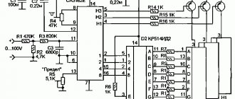
When testing transformers, you can use the diagram below. If switched on incorrectly, the FU fuse will protect the network from short circuit and the transformer from damage.
We calculate the fuse current in the usual way:
I=P/U
I – current for which the fuse is designed (Ampere),
P – overall power of the transformer (Watt),
U – mains voltage (~220 Volts).
Example:
35 / 220 = 0.16 Ampere
The closest value is 0.25 Ampere.
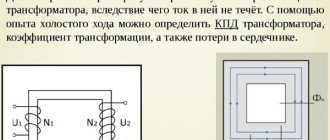
Circuit for measuring the no-load current (IO) of the transformer. The XX current of the transformer is usually measured to exclude the presence of short-circuited turns or to ensure that the primary winding is connected correctly.
When measuring the XX current, you need to gradually increase the supply voltage. In this case, the current should increase smoothly. When the voltage exceeds 230 volts, the current usually begins to increase more sharply. If the current begins to increase sharply at a voltage significantly less than 220 Volts, it means that either you have chosen the primary winding incorrectly, or it is faulty.
| Power, W) | Current XX (mA) |
| 5 — 10 | 10 — 200 |
| 10 -50 | 20 — 100 |
| 50 — 150 | 50 — 300 |
| 150 — 300 | 100 — 500 |
| 300 — 1000 | 200 — 1000 |
Approximate currents of XX transformers depending on power.
It should be added that the currents of XX transformers, even of the same rated power, can differ greatly. The higher the induction values included in the calculation, the lower the idle current.
Connection diagram for determining the number of turns per volt.
Return to top menu
How vector diagrams are constructed
When constructing vector diagrams, you need to remember the rule that the phase shift between the phases is 1200, that is, if the voltages are equal, the ends of the vectors will always form an equilateral triangle.
The simplest diagram to draw is for a star connection. A point is placed in the center of the diagram, which corresponds to the combined ends of the windings. Phase vectors are drawn from the center at angles of 1200. The vector of the middle phase is drawn vertically.
For a triangle, draw a line parallel to the corresponding phase of the star, and from its ends, respectively, the remaining two phases are connected to it. The condition must be met - all sides of the triangle must be parallel to the corresponding phases of the star. The required vectors will be lines drawn from the center of the triangle to its vertices.
Vector diagrams are drawn for the high and low sides and then aligned with a single center. The angle between like phases will indicate the connection group number expressed in hours.
The count must be taken from the high voltage vector to the low one.
Connection group table
The table below shows the designations of the connection groups and the phase rotation of the low and high sides.
| Connection group | Designation | Phase rotation |
| 0 | Y/Y-0 | C, B, A |
| c, b, a | ||
| ∆/∆-0 | C, B, A | |
| c, b, a | ||
| 1 | Y/∆-1 | C, B, A |
| c, b, a | ||
| ∆/Y-1 | C, B, A | |
| c, b, a | ||
| 2 | Y/Y-2 | C, B, A |
| c, b, a | ||
| ∆/∆-2 | C, B, A | |
| a, c, b | ||
| 3 | Y/∆-3 | C, B, A |
| b, a, c | ||
| ∆/Y-3 | C, B, A | |
| b, a, c | ||
| 4 | Y/Y-4 | C, B, A |
| b, a, c | ||
| ∆/∆-4 | C, B, A | |
| b, a, c | ||
| 5 | Y/∆-5 | C, B, A |
| c, b, a | ||
| ∆/Y-5 | C, B, A | |
| c, b, a | ||
| 6 | Y/Y-6 | C, B, A |
| c, b, a | ||
| ∆/∆-6 | C, B, A | |
| c, b, a | ||
| 7 | Y/∆-7 | C, B, A |
| c, b, a | ||
| ∆/Y-7 | C, B, A | |
| c, b, a | ||
| 8 | Y/Y-8 | C, B, A |
| a, c, b | ||
| ∆/∆-8 | C, B, A | |
| c, b, a | ||
| 9 | Y/∆-9 | C, B, A |
| b, a, c | ||
| ∆/Y-9 | C, B, A | |
| b, a, c | ||
| 10 | Y/Y-10 | C, B, A |
| c, b, a | ||
| ∆/∆-10 | C, B, A | |
| b, a, c | ||
| 11 | Y/∆-11 | C, B, A |
| c, b, a | ||
| ∆/Y-11 | C, B, A | |
| c, b, a |
Determination by galvanometer method
There are several ways to determine whether the windings are connected correctly. The easiest way is to use a magnetoelectric system voltmeter. It is also called the direct current method.
To do this, a measuring device is connected to the ends of the winding being tested, and a constant voltage is applied to the other winding. The deflection of the arrow at the moment the key is closed will indicate the polarity of the winding connection. Such actions are performed for each winding.
You can also use a simple voltmeter when connecting AC voltage. To do this, a reduced alternating voltage is supplied to one of the windings, and the remaining two windings are connected in series and connected to a voltmeter. Absence or too small readings indicate that the windings are connected in opposite directions.
Transformer electrical circuit
In Russia, the era of converting voltage from one value to another originates from the work on the study of ferromagnetic materials by the great Russian physicist Alexander Grigorievich Stoletov, who first discovered the hysteresis loop in the 1880s, as well as the redistribution of domains in a ferromagnetic material when exposed to an electromagnetic field .
Previously, then not yet studied, this effect allowed Michael Faraday to identify in 1831 the possibility of energy transfer across the entire plane of a ferromagnetic material - the so-called phenomenon of electromagnetic induction. 17 years later, Heinrich Daniel Ruhmkorff first laid out the prototype of a graphic image of a magnetized coil.
The first AC transmission transformer was a ferromagnetic rod with multiple windings. This invention was recorded by the issuance of a patent to Pavel Nikolaevich Yablochnikov in 1876, but the transformer in its modern representation was presented a year later in 1877 by Dmitry Nikolaevich Motovilov. At the same time, the first electrical circuit of a transformer appeared, displaying two windings on a ferromagnetic material.
Soon in London in 1884, at the Growner Gallery station (it is believed that the first power station appeared here), series-connected Golyar and Gibbs transformers based on a closed core were used. Two years earlier, Thomas Edison's first steam generators were installed in the gallery. In the same year, brothers Edward and John Hobkinson produced the first closed-core transformers. Industrial production of closed-core transformers began in 1885 in the Hungarian electrical engineering industry. These were structures based on ring, armor and rod cores. In the same year, Hungarian designer Max Dery received a patent for the design of transformers with parallel connection. The first models immediately revealed one significant drawback - rapid overheating of the magnetic circuit due to the large load of consumers, which rendered the transformer windings unusable. In 1889, the Swedish inventor D. Swinburne, to reduce overheating of the windings, immersed a working transformer in a ceramic vessel filled with oil, calling it an “oil transformer.” In the same year, Swedish engineer Johns Wenstrom invents a three-phase system for generators, transformers and electric motors. At this time, a three-phase electrical circuit of a transformer appeared, which was invented by the Russian scientist M. O. Dolivo-Dobrovolsky, and already in 1891, Charles Brown and Walter Boveri organized a high-voltage energy transmission company in the Swiss city of Baden. The demand for electricity grew exponentially and in 1893 the Brown-Boveri company provided Europe with the first industrial power plant based on the use of three-phase transformers. Electricity was generated by Edison's steam generators. In the Russian Empire, the already mentioned Odessa Opera House launched one of the first alternating current installations for its lighting. This happened in 1887.
Since then, development in this area has stepped far forward and today there are 7 transformer classifiers. Transformers are divided by purpose: - Power transformers - a fairly general concept that combines the use of transformers in static converters to convert alternating current into direct current (rectifiers), or, conversely, from direct current to alternating current (inverters). Their main purpose is to convert one voltage and current value into another voltage and current value without changing the power (taking into account, of course, losses due to leakage induction). — Power transformers for special purposes - most often they can be found in old welding machines, low- or high-frequency devices (in electrical equipment of railways), etc. — Test transformers are used to obtain high or ultra-high voltages and currents. In industry, they are used to check the breakdown of insulation (ceramic insulators, for example), in high-voltage testing laboratories. Long-term operation of such transformers is excluded. — Instrument transformers include voltage and current transformers. They are used primarily in power electronics or in electrical installations with high voltage, where it is necessary to measure high-voltage circuits with standard measuring equipment. — Until very recently, radio transformers were used in power supplies for consumer electronics radio devices. This type is also used for matching resistance in interconnect connections of electrical circuits. Today, in power supplies they have been replaced by pulse technology, and radio transformers are used only in devices that are critical to the purity of the supply voltage (powerful, expensive audio amplifiers, for example).
Based on the type of cooling, transformers are divided into dry and oil-based. The number of phases in the power winding divides transformers into single-phase and three-phase. There is also a classification based on the shape of the magnetic circuit: rod (linear transformers in television equipment), armored, toroidal and oval.
The electrical circuit of a transformer in its simplest design must contain at least two windings. Such transformers are called double-winding. If there are more than two windings, then they fall into the multi-winding class. The design of transformer windings divides them into cylindrical, disk and concentric.
Based on the ratio of windings, transformers are divided into step-up transformers - if the voltage of the secondary winding is greater than the power winding, and step-down transformers (correspondingly, vice versa).
The principle of operation of the device is clearly visible from the electrical circuit diagram of the transformer.
The primary winding W1, when an alternating voltage source U1 is connected to it, due to the flow of current I1 induces an alternating magnetic flux F in the core of a magnetically conductive material, which, in turn, induces an emf E1 and E2 in the primary and secondary (W2) windings. Due to the transformation ratio (the ratio of the emf or the number of turns of the primary winding to the secondary) and the effect of magnetic induction in the winding W2, when a load Zn is connected, a current I2 begins to flow. Voltage U2 appears at the load.
The transformation ratio determines the ratio of the EMF or the number of turns of the primary winding to the secondary. If the value of K>1, then the transformer is considered to be step-down, if K<1, then it is considered to be step-up. The same transformer, depending on the winding of the connected voltage source, can be both step-down and step-up.
The ability to transmit energy through a magnetic circuit without losses, which will be inevitable, determines the efficiency of the transformer. Modern factory-made transformers allow achieving efficiency of up to 99%. The main reasons for the decrease in efficiency in transformers are magnetic losses in the core due to eddy currents and hysteresis (energy loss due to magnetization reversal of the core), the resistivity of the transformer windings, the quality of the winding, the size of the connected load in relation to the overall power of the core.
Many computer programs that allow simulation of the operation of electronic circuits use an electronic equivalent circuit of the transformer to process the results of the physical processes of energy conversion by a transformer. In such a circuit, magnetic coupling is usually replaced by an electrical circuit. There are 2 types of transformer emulation circuits: T-shaped and simplified.
In this electrical equivalent circuit of the transformer, magnetic connections are replaced by electrical ones. R1 and X1 together with R2 and X2 represent the electrical emulation of the primary and secondary windings of the transformer, and R0 and X0 represent magnetization and no-load. If we take into account an ideal lossless transformer, then the electrical circuit of the transformer will look like this.
On January 1, 1970, a unified international GOST for conditional graphic display of transformers was approved. According to GOST 2.723-68, the electrical diagram of a transformer can be displayed in 3 options: simplified single-line, simplified multi-line and expanded. A simplified display of the UGO (conditional graphic display) represents the magnetic coupling of the transformer in the form of a circle.
For example, a three-phase autotransformer with a ferromagnetic magnetic core and nine terminals will be displayed on the diagram as follows. This type of transformer wiring diagram display is more common in older circuit diagrams from the 70s. Modern circuit diagrams use UGO low-frequency transformers of the 2nd type in the form of a designation of two chokes and a ferromagnetic material - (transformer with a magnetodielectric core). The electrical circuit of a pulse-type transformer is increasingly found in this designation.
Recently, modern consumer electronics have almost completely switched to using switching circuitry in power supplies. Its advantage is obvious - smaller weight and dimensions, higher efficiency and better power indicators of power supplies. Many solutions today use transformers with high permeability cores of 400HH and above. Such transformers are called high-frequency or, in common parlance, pulse transformers. Disassemble any switching computer power supply, and you will see its circuitry and transformers as well. For example, the circuit diagram below shows the implementation of a powerful charger (or power supply) based on the popular PWM controller UC3842, power field-effect transistor UFN432 and high-frequency power transformer with insulated magnetic material T1.
Pulse transformer cores are produced with and without a non-magnetic gap. The non-magnetic gap is used to ensure that, under the influence of large induction currents, the ferromagnetic core does not enter saturation, which is fraught with a decrease in efficiency, rapid overheating of the transformer and its failure. As a rule, such transformers are used in switching power supplies operating on the flyback principle (single-cycle energy conversion). In fact, pulses of a frequency specified by the PWM are supplied to its primary winding through a power switch. EMF accumulates in the core during the working period of the pulse, and at the moment of pause, the accumulated energy, according to the transformation ratio, is transferred to the load by the secondary winding. That is, in practice we get a two-winding inductor. The above circuit (and most circuits of network step-down switching power supplies) works precisely on this principle. Network pulse welding machines (for the most part) also use this type of core.
Cores without a non-magnetic gap (torroidal, armored, etc.) are more often used in the topology of pulse converters according to the Push-pool scheme. This technology is more often used in pulsed boost/buck converters when it is necessary to convert one DC voltage into a different voltage. For example, according to the diagram below, a simple power supply for a car audio amplifier is implemented.
In this electrical circuit, the operation of transformer T1 is similar to the operation of a conventional transformer, that is, rectangular pulses (ideally) are supplied to windings I and II alternately through switches VT3 and VT4. Through the transformation ratio, the voltage is removed from windings III and IV. Perhaps the reader will ask the question that if the pulses go continuously, then, in fact, this is the same constant voltage, which will lead to through currents in the primary winding of our transformer and transistors, which will lead to almost instantaneous failure. Especially for this purpose, any PWM chip contains a parameter such as “dead time”, which specifies a pause in the supply of pulses to one switch and the other. With this time, we can change the strength of the electromagnetic field and its inductance, thereby adjusting the voltage level at the output of the converter. The study of the operation of a pulse transformer takes up quite extensive material, which is not included in the specifics of this article.
An electrical circuit using a pulse transformer requires competent calculation and selection of the element base, because such a circuit solution is primarily high-frequency, which implies the use of specific radio components (transistors with low transition resistance, low-impedance capacitors, calculation of critical resistance powers, etc.). A particularly important point is the calculation of the pulse transformer. Without going into details, let's say that the simplest and most convenient computer programs for calculating pulse transformers are the programs of a person with the nickname Starichok (Vladimir Denisenko) from Pskov.
Flyback is a program that allows you to calculate a pulse transformer for a flyback converter or power supply.
ExcellentIT is a program for calculating a pulse transformer for a push-pull converter.
Tranz50Hz – calculation of a power transformer for an electrical 50Hz network on various cores.
All of its programs have a user-friendly interface, an extensive database of factory core parameters, and a help file. In addition, the author answers the questions asked without any problems. These and many other programs are present in the author’s threads on radio-electronic forums.
Examination
If the transformation ratio is known, then using a voltmeter you can determine the number of the main connection group. For this purpose, voltage is applied to ends A and a or x and y and the voltages are measured at terminals B-c and C-c when connected in a star, or By and Cz when connected in a triangle. The following ratios are used for verification:
UBb = UCc = UAa(k-1) Group Y/Y-0
UBy = UCz = Uxy(k+1) Y/Y-6
UBb = UCc = UAa(√(1-√3k+k2)) Y/∆-11
UBy = UCz = Uxy(√(1+√3k+k2)) Y/∆-5
To avoid equipment damage, emergency situations and injury, all measurements should be made at low voltage, without connecting the equipment to the main network of the enterprise.
Welding transformers
There are special welding transformers.
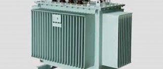
Welding transformer
The welding transformer is designed for electric arc welding; it works as a step-down transformer, reducing the voltage on the secondary winding to the required value for welding. The voltage of the secondary winding is no more than 80 Volts. Welding transformers are designed for short-term short circuits of the output of the secondary winding, in which an electric arc is formed, and the transformer does not fail, unlike a power transformer.
Examples of group winding connections
The state standard provides only two groups of winding connections:
- Y/Y-0 or ∆/∆-0
- Y/∆-11 and ∆/Y-11
Strict standardization eliminates accidents and damage resulting from incorrect connections. In addition, for transformers of the same power and transformation ratio, parallel connection of devices becomes possible.
The remaining number of connections is used extremely rarely in some cases when it is impossible to use the standard option.
The type of connection must be specified in the accompanying documentation and duplicated on the device nameplate.
The given parameters of the transformer
To analyze the operation of a transformer as an electrical device, the so-called equivalent circuit or equivalent circuit is used. This circuit contains all the main parameters of the transformer used in calculations and theory. An equivalent circuit is built for the so-called reduced transformer, when the number of turns of the secondary and primary windings is considered the same. The reduction of the number of turns of the winding is accompanied by the reduction of all other parameters of the transformer: voltage, currents and resistances. The given parameters of the secondary winding are calculated using the following expressions
where n is the transformation ratio,
U'2, I'2, Z'2 – given parameters of the secondary winding: voltage, current, resistance,
U2, I2, Z2 – real parameters of the secondary winding: voltage, current, resistance.
These expressions correspond to the parameters of the secondary winding reduced to the primary. If necessary, you can adjust the parameters of the primary winding to the secondary. In this case, the transformation ratio will be equal to the ratio of the turns of the secondary winding ω 2 to the primary winding ω 1 .
Erroneous designations
Erroneous connections occur when the rules for connecting the ends are not followed. This occurs as a result of incorrect winding or incorrect designation. As a result, when the device is connected to a three-phase network, the windings connected in opposite directions compensate each other’s magnetic fluxes, so a current begins to flow through them, limited only by the active resistance of the winding wire, which is equivalent to a short circuit.
To eliminate cases of incorrect switching, it is recommended that after repairing equipment or before switching on unknown devices, carefully check the phasing of each winding using several methods to eliminate possible errors.
A preliminary calculation of voltages for measurements using the voltmeter method will help reduce the likelihood of error. The data obtained serve as guide values that need to be taken into account when making subsequent measurements.