Any transformer, with the exception of an autotransformer, has at least two windings: high and low voltage. Also, for three-phase devices, each of the windings consists of three parts (according to the number of phases). The large number of parts allows for multiple inclusion options. To avoid confusion, all transformer winding connection groups for three-phase devices are standardized and brought into a single system for error-free connection of devices and the possibility of parallel operation.
Electrical device design
Transformation of three-phase current does not necessarily imply the use of one transformer having a common magnetic circuit. Although such installations are widely used in the national economy.
There is the possibility of such a transformation using three separate single-phase transformers that are not magnetically connected to each other, that is, each individual phase will have its own separate magnetic circuit.
A transformer made according to this scheme is called a group transformer. The primary and secondary windings of the device are interfaced with each other according to one of the schemes adopted for transforming three-phase current.
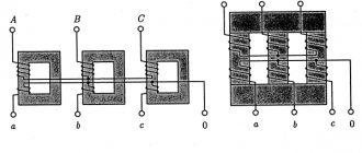
Structurally, a three-phase transformer is a three-rod magnetic circuit with windings located on each of the rods, made in the same way as for single-phase devices.
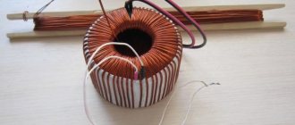
Interesting material on the topic: how a toroidal transformer works.
Let's imagine three single-phase transformers placed next to each other so that their three rods form one common central rod. On each of the other three rods there are primary and secondary windings.
The currents in the transformer coils will create time-varying magnetic fluxes, which will each be closed in its own magnetic circuit. In the central composite rod, the magnetic fluxes will add up and give a total of zero, because these fluxes are created by symmetrical three-phase currents, regarding which we know that the sum of their instantaneous values is equal to zero at any moment of time.
Let us assume that the primary coils of all transformer bars are exactly the same and wound in the same direction. We connect all the upper ends of the coils to neutral O, and connect the lower ends of the coils to the three terminals of the three-phase network. The magnetic cores are made of sheet electrical steel. To weaken eddy currents and reduce magnetization reversal losses, steel sheets are insulated with varnish before assembly.
Detailed design of a three-phase transformer.
Basic formulas
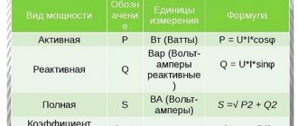
Before you get acquainted with the features of how to connect a star-delta electric motor, it is worth remembering the basic formulas for calculating power and the ratio of voltages and currents between them. When calculating devices powered by an alternating voltage network or a separate transformer, the concept of total power is used. It is denoted by the capital letter S and is found as the product of the effective value of voltage and current U × I. Also, it is possible to calculate based on the EMF, at which S = E × I.
In addition to the full one, there are also:
- active;
- reactive power.
In the first case, it is denoted by the letter P = E × I × cos φ or P = U × I × cos φ. In the second case, Q = E × I × sin φ or Q = U × I × sin φ. Where in the formulas E is the electromotive force, I is the current, φ is the angle between the voltage and current created by the phase shift in the windings.
If the motor windings are identical to each other in all respects, then all types of power are determined as the product of current and voltage multiplied by 3.
Magnetic Circuit Location
Three-phase core transformers are divided into transformers with a symmetrical magnetic circuit and transformers with an asymmetrical magnetic circuit. The arrangement of the rods in the same plane leads to the fact that the magnetic resistance for the middle phase flow is less than for the outer phase flows.
Indeed, the magnetic fluxes of the extreme phases travel along slightly longer paths than the flux of the middle phase. In addition, the flow of extreme phases, having left their rods, passes completely in one half of the yoke, and only in the other half (after branching into the middle rod) does half of it pass. The flow of the middle phase, upon exiting the vertical rod, immediately branches into two halves, and therefore only half of the flow of the middle phase passes through both parts of the yoke.
Thus, the flows of the extreme phases saturate the yoke to a greater extent than the flow of the middle phase, and therefore the magnetic resistance for the flows of the extreme phases is greater than for the flow of the middle phase.
A consequence of the inequality of magnetic resistances for the flows of different phases of a three-phase transformer is the inequality of no-load currents in individual phases at the same phase voltage. However, with low saturation of the iron of the yoke and good assembly of the iron of the rods, this inequality of currents is insignificant.
Since the design of transformers with an asymmetrical magnetic circuit is much simpler than that of a transformer with a symmetrical magnetic circuit, the first transformers found their primary application. Transformers with a symmetrical magnetic circuit are rare.
It will be interesting➡ How does a power transformer work and where is it used?
Main types of device
The main group of three-phase transformers are armored transformers. An armored three-phase transformer can be considered as consisting of three single-phase armored transformers, placed one next to the other with their yokes. It can be divided into three single-phase armored transformers, the magnetic fluxes of which can each be closed along its own magnetic circuit.
In core transformers, the windings are almost entirely open and therefore more accessible for inspection and repair, as well as for the cooling medium. There are a number of advantages and disadvantages based on which type of transformer is chosen.
Pros and cons of armored transformers over rod transformers.
The devices are switched according to various winding connection schemes. Group three-phase transformers are used in the presence of very high powers, from 630 kVA per phase.
Using a group transformer under such conditions is advisable because the dimensions and weight of the product are significantly smaller than a similar unit operating at the total power of the group.
Moreover, when using a single transformer, in order to have reserve power, you have to install another similar device, and in a group transformer, one of three single-phase ones can be used as a backup.
This determines the choice of group transformers for the stated purposes, despite the fact that they have lower efficiency, larger dimensions and are somewhat more expensive compared to single analogues.
You can read more about the design of transformers in the material on current transformers.
Classifications
Transformers are classified according to a number of parameters, such as:
- Purpose. Used: for changing voltage, measuring current, protecting electrical circuits, as laboratory and intermediate devices.
- Installation method. Depending on the location and mobility, the transformer can be: stationary, portable, internal, external, support, busbar.
- Number of steps. The devices are divided into single-stage and cascade.
- Rated voltage. There are low and high voltage.
- Winding insulation. The most commonly used are oil-paper, dry, and compound.
In addition, converter devices come in different types, each of which has its own classification system.
Power
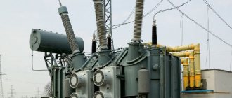
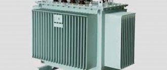
The most widely used type is the power transformer. Devices with direct conversion of alternating voltage, designed for high power, are in demand in various areas of the electric power industry. They are used on power lines with voltages of 35–1150 kV, in city power networks operating with voltages of 6 and 10 kV, and in providing end consumers with voltages of 220/380V. The devices provide power to all kinds of electrical installations and devices in the range from fractions to hundreds of thousands of volts.
Power transformer
Measuring
Current transformers (CTs) reduce the current to the required levels. The scheme of their operation is distinguished by the sequential connection of the primary winding and load. At the same time, the secondary winding, which is in a state close to a short circuit, is used to connect measuring instruments, actuators and indicator devices. With the help of TA, galvanic isolation is carried out, which makes it possible to avoid using shunts during measurements.
High voltage CT(left) and low voltage CT(right)
With the help of voltage transformers (VT), the same as TA only in voltage. In addition to converting input parameters, electrical equipment and its individual elements are protected from high voltage.
High voltage transformer (left) and low voltage transformer (right)
Pulse
If it is necessary to convert pulsed signals, pulse transformers (IT) are used. By changing the amplitude and polarity of the pulses, the devices maintain their duration and practically do not affect the shape.
Autotransformer
In autotransformers, the windings form one circuit and interact through electromagnetic and electrical communication. Unlike other types of converters, devices can contain only 3 outputs, allowing you to operate with different voltages. The devices are distinguished by their high efficiency, which is especially noticeable with a slight difference in input and output voltage.
Single-phase (left) and three-phase (right)
Without galvanic isolation, representatives of this type increase the risk of high-voltage shock to the load. A prerequisite for the operation of devices is reliable grounding and a low transformation ratio. The disadvantage is compensated by lower consumption of materials during manufacturing, compactness and weight, and cost.
Dividing
For isolation transformers, interaction between the windings is eliminated. The devices increase the safety of electrical equipment in the event of damaged insulation.
Isolation transformer
Coordinator
Matching transformers are used to equalize resistance between stages of electronic circuits. While maintaining the signal shape, they play the role of galvanic isolation.
Peak transformer
Using a peak transformer, sinusoidal voltage is converted into pulse voltage. In this case, the pulses change polarity with each half-cycle.
Twin throttle
A feature of a dual inductor is the identity of the windings. The mutual induction of the coils makes it more efficient than standard chokes. The devices are used as input filters in power supplies, audio and digital equipment.
Twin throttle
Welding
In addition to the above, there is the concept of welding transformers. Specialized devices for welding work lower the voltage of the household network while simultaneously increasing the current, measured in thousands of amperes. The latter is adjusted by dividing the windings into sectors, which affects the inductive reactance.
Welding transformer
Rod type magnetic core
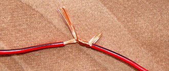
To power radio-electronic devices, three-phase transformers with a common magnetic system through a yoke I for three phases with three rods C, or three-rod transformers are usually used. Each of the transformer windings, both primary and secondary, can be connected: a) by a star; b) a triangle.
When connected by a star, the ends of the windings form a common point 0. When connected by a triangle, the beginning of the first phase winding is connected to the end of the third, the beginning of the second - to the end of the first, and the beginning of the third - to the end of the second. In the first case, everything starts, and in the second, the common points of the windings are connected to the network.
It should be noted that the concepts of the beginning and end of the windings are conventional, but they are necessary for the correct connection of the phase windings. In three-phase transformers, the positive direction of the current from the beginning to the end of the winding must correspond to a certain direction of the magnetic flux in the rods; in core transformers this direction must be the same.
Winding connection: a - star; b - triangle.
The beginnings of high voltage (HV) phase windings are usually designated by capital (capital) letters A, B and C, and their ends by letters X, Y and Z, and for phase windings the letters AX, VU and CZ are used. The beginnings and ends of low voltage (LV) windings are designated, respectively, by lowercase (small) letters - a, b, c and x, y, g.
The most common winding connections are “star” (Y) and “delta” (D), and the primary and secondary windings can have either the same or different circuits. If, when connecting the windings with a star, the zero point is output, then such a connection is called “star with zero” (Yo).
Star connection of windings
The simplest and cheapest of them is to connect both windings of the transformer with a star (Y/Y), in which each of the windings and its insulation (with solid grounding of the neutral point) should be designed only for phase voltage and line current.
Star connection of transformer windings.
Since the number of turns of a transformer winding is directly proportional to the voltage, therefore, a star connection of the windings requires a smaller number of turns in each winding, but a larger cross-section of conductors with insulation designed only for phase voltage.
A three-phase transformer has windings connected in a star (Y/Y). This connection is widely used for small and medium power transformers (up to approximately 1800 kVA). The star connection is most desirable for high voltage, since in it the insulation of the windings is calculated only for the phase voltage. The higher the voltage and lower the current, the relatively more expensive it is to connect the windings with a delta.
Where is triangle winding used?
Connecting the windings with a triangle is structurally more convenient at high currents. For this reason, the Y/D connection is widely used for high power transformers where a neutral wire is not required on the low voltage side.
With three-phase transformation, only the ratio of phase voltages U1ph/U2ph is always approximately equal to the ratio of the numbers of turns of the primary and secondary windings w1/w2; As for linear voltages, their ratio depends on the method of connecting the transformer windings.
Connection of transformer windings with a triangle.
With the same connection method (Y/Y or D/D), the ratio of line voltages is also equal to the transformation ratio. However, with different connection methods (Y/D or D/Y), the line-to-line voltage ratio is √3 times less or more than this ratio. This makes it possible to regulate the secondary line voltage of the transformer by correspondingly changing the method of connecting its windings.
The operating characteristics of transformers are influenced by energy losses during heating of the windings in combination with other external and internal factors that significantly complicate the relationship of the secondary voltage shape with similar parameters of the primary circuit.
Connection of electric motor windings with triangle and star
Today, high-power asynchronous electric motors are distinguished by reliable operation and high performance, ease of operation and maintenance, as well as reasonable prices. The design of this type of engine allows it to withstand strong mechanical overloads.
As is known from the basics of electrical engineering, the main parts of any engine are a static stator and a rotor rotating inside it.
Both of these elements consist of conductive windings, while the stator winding is located in the grooves of the magnetic core maintaining a distance of 120 degrees. The beginning and end of each winding are brought out into an electrical distribution box and installed in two rows.
When voltage is applied from a three-phase power supply to the stator windings, a magnetic field is created. This is what makes the rotor rotate.
An experienced electrician knows how to connect an electric motor correctly.
The connection of an asynchronous motor to the electrical network is carried out only according to the following schemes: “star”, “triangle” and their combinations.
Determination of device currents
When determining the primary winding current, losses should be taken into account, as well as the magnetizing current of the transformer, the relative magnitude of which in low-power power transformers is very significant. The current values can be determined using the following formula:
It will be interesting➡ Necessary conditions for parallel operation of transformers
where U1 and U2 are the voltages of the windings as specified;
P2 – power of the secondary winding as specified;
cos φ2 – load power factor according to the specification;
η – coefficient of performance (efficiency) of the transformer.
The choice of induction in the core rod and current density in the wires of the transformer windings - the permissible value of induction in the rod and yoke of the transformer core is determined by the selected value of the magnetizing current, power, frequency, type of transformer, number of joints in the core and the material of the latter.
You can read the article in more detail about the design of power transformers.
How to choose a current transformer for a meter: 10 criteria according to GOST
Long-term and reliable operation of the CT is possible if its design complies with:
- purpose. (We focus only on measuring products);
- the current voltage of the electrical wiring, which can vary from 220 volts to high-voltage values;
- type of insulation;
- acceptable installation method (in closed distribution devices or outdoors);
- the magnitudes of effective currents taken into account by the transformation ratio;
- accuracy class;
- a number of other requirements.
In addition, it will be necessary to clarify the design of the primary winding, which can be manufactured:
- rod or tire;
- with the possibility of installing one turn or several.
To operate different measurement, protection or automation circuits, several secondary windings with different characteristics can be made inside the CT housing. All of them will have to be taken into account, and the unnecessary ones will have to be reliably bypassed.
GOST 7746-2001 Table 5 defines the values of 10 main parameters that ensure reliable operation of CTs as measuring devices for electric meters.
More detailed information is provided within this GOST.
Transformer power circuits
The permissible current density in the wires of the transformer windings largely determines the weight and cost of the latter. The higher the current density in the windings, the lower their copper weight and, accordingly, the cost of the transformer. On the other hand, with increasing current density, losses in the copper of the windings and heating of the transformer increase.
Power supply diagram for a traction network of a 2×25 kV system using a three-phase transformer with step-up autotransformers.
The simplest is the power supply circuit for the traction network of a 2×25 kV system using a three-phase transformer and step-up autotransformers. A special feature of the circuit is that to increase the voltage to 55 kV, a conventional linear autotransformer AT is used, which is connected to the contact network and the supply wire, and transformer T is connected between the contact network and the rails.
Autotransformers are installed on the terminals of a 27.5 kV transformer or on the feeders of the contact network. The latter option is preferable, since it allows you to have only contact network buses at the substation, and autotransformers can be installed outside the territory of the traction substation.
In the scheme, a significantly larger part of the electricity is supplied to electric locomotives directly along the contact network - rails circuit, bypassing the step-up autotransformer.
This circumstance makes it possible to install step-up autotransformers at a substation of the same power as in the feeder zone, and not reserve them at the substation. When the autotransformer at the substation is disconnected, the autotransformer closest to the substation in the feeder zone takes on the role of step-up.
Star motor connection
The most commonly used is the star connection, because in this mode the necessary power is provided and good torque on the shaft is guaranteed. But it is worth understanding that an underloaded motor in a 3-phase network will consume excess power, so it is better to use a less powerful motor or adjust the frequency of the supply transformer or drive, depending on the voltage source.
And to determine the electrical parameters of the network, it is necessary to use the relation √3. Initially, it should be noted that when connected in a star, the linear and phase currents are the same, and the voltage is determined by the formula U = √3 × U f. It is not difficult to find the phase voltage from it. Accordingly, powers are determined taking into account this ratio:
S = √3 × U × I
It should be remembered that if the transformer, in addition to 3 phases, also has a 4th terminal from the middle point, then it must be connected to the electric motor.
How to increase energy transfer
It is possible to increase the transmission of electricity along the supply wire-rail circuit by installing special step-up autotransformers at substations, the power of which corresponds to the load of the substation power arm, or by specially connecting two standard three-phase transformers at the substation.
The U/D-1 connection group of the second transformer is obtained by the same double relabeling of the terminals of the two phases of the primary and traction windings of the standard transformer. The designation of the secondary winding terminals according to the factory markings is shown in the figure with the index “T”.
The same terminal of the traction winding of both transformers is connected to the rails, as in the 25 kV system (terminal st according to the factory marking). The connection with the st output rails determines that the windings on the middle rod will be the least loaded for both transformers.
By analogy with three-phase transformers in a 25 kV system, if a wire is connected to terminal at, we have a positive voltage of this wire relative to the rails, and to terminal bm, we have a negative voltage of the wire relative to the rails.
Power supply diagram for the traction network of a 2×25 kV system with a series connection of two phases of three-phase transformers (a), vector diagrams of the voltages of the primary and secondary windings (b).
The first transformer is connected by its terminal am to the contact network of the first feeder zone, and by its terminal bm to the contact network of the second feeder zone.
The second transformer has a reverse connection: with its terminal yat it is connected to the supply wire of the second feeder zone, and with its terminal bm - to the supply wire of the first feeder zone.
The sequential connection of two secondary windings of transformers with winding connection groups U/D-11 and U/D-1 makes it possible to obtain double the voltage of the two phases supplying the traction network on opposite sides of the substation.
It will be interesting➡ Transformers for LED strips, expert opinion
As above, at the contact network and the supply wire, and the voltages of the supply line are indicated, with which the voltage of the contact network and the supply wire coincide in phase. The latter are shifted by 180°. Therefore, the figure shows the position of only the contact line-rail voltages. It does not differ from the position of these vectors in a 25 kV system, if in a 2x25 kV system the transformer connected to the contact network is connected to the same phases of the supply line as in the 25 kV system.
Engine design
The windings are located on the stator, and the rotor is short-circuited in the form of a squirrel wheel: aluminum or copper rings at the ends are connected to each other by parallel jumpers. The stator is wound in a special way with a certain number of poles, which depends on the power parameters and the supply network. Household fans have only 2 poles, industrial traction motors have 8 or more.
The advantages of using asynchronous electric motors with a star or delta connection circuit are obvious and are as follows:
- Increased endurance - even at loads exceeding the rated load, the engine will operate without failure.
- Ability to work in aggressive environments. Due to the absence of sliding contacts, sparking cannot occur in the engine, and, consequently, problems associated with it. With high-quality insulation, the electric motor can operate in damp environments.
- Long operating time at high loads. The engine is capable of operating for a long period of time under significant load on the shaft without overheating and burning out the windings.
Beginners, and not only others, will find this article about the parameters, pinout and analogues of the KT815 transistor useful.
Scheme of operation when one of the transformers is disconnected
In the event that a transformer connected to the supply wire buses is disconnected at the substation, we will have the circuit practically considered in the figure with step-up autotransformers, the role of which is played by the autotransformers closest to the substation in the feeder zones.
At the same time, in the sections from the substation to the autotransformers closest to it we have a 25 kV system, and in most of both feeder zones the 2x25 kV system remains. Since the resistance of sections with a 25 kV system is greater than their resistance with a 2x25 kV system, neighboring substations take on a greater load.
If a transformer connected to the contact network buses is disconnected at a substation, the autotransformers closest to the substation will operate in transformer mode and, with significant traffic volumes or heavy trains, may be overloaded.
Scheme of operation when one of the transformers is turned off.
This can be avoided either by switching to one-way power supply to feeder zones from neighboring substations during the shutdown of the specified transformer, or by bringing the connection group of an operational transformer into correspondence with the group of the disconnected transformer and connecting it to the contact network buses.
To do this, it should be possible to quickly switch two phases on the primary side of the transformer connected in normal mode to the supply wire buses.
If it is necessary to have a greater degree of redundancy of transformers, it is possible, as in the case of single-phase transformers, to use a third three-phase transformer as a backup with the ability to connect it to the 110 (220) kV buses and to the buses of the contact network or supply wire instead of any transformer taken out of operation.
The considered schemes of substations with three-phase transformers are promising on the roads of the CIS countries at the junction of 25 and 2×25 kV systems and at traction substations, if necessary, to power a large regional load from them, as well as when strengthening the power supply system of previously electrified lines.
General information
Voltage transformers are used to convert high voltage to low standard values (100, 100/√3, 100/3 V), used to power measuring instruments and various control, protection and automation relays. They, like current transformers, isolate (separate) measuring instruments and relays from high voltage, ensuring the safety of their service.
According to the design principle, switching circuit and operating features, electromagnetic voltage transformers differ little from power transformers. However, compared to the latter, their power does not exceed tens or hundreds of volt-amperes. At low power, the operating mode of voltage transformers approaches the idle mode. Opening the secondary winding of a voltage transformer does not lead to dangerous consequences.
At voltages up to 35 kV, voltage transformers, as a rule, are switched on through fuses so that if the voltage transformer is damaged, it does not cause an accident. At voltages of 110 kV and above, fuses are not installed, since, according to available data, damage to such voltage transformers rarely occurs.
Voltage transformers are switched on and off using disconnectors.
To protect the voltage transformer from short circuit current, removable tubular fuses or overcurrent circuit breakers are installed in the secondary circuits. Fuses are installed if the voltage transformer does not supply high-speed protection, since these protections may act falsely if the fuse-link does not burn out quickly enough. The installation of automatic circuit breakers ensures the effective operation of special interlocks that disable certain types of protection in the event of a break in voltage circuits.
For safe maintenance of secondary circuits in the event of an insulation breakdown and high voltage entering the secondary winding, one of the secondary winding terminals or the zero point is connected to ground. In circuits for connecting secondary windings in a star, it is not the zero point that is grounded, but the beginning of the phase b winding. This is explained by the desire to reduce the number of switching contacts in secondary circuits by 1/3, since the grounded phase can be supplied to the relay in addition to switches and auxiliary contacts of disconnectors.
Rice. 4.1. Diagrams of voltage transformers of types NKF-110 (a), NKF-220 (b): VN – primary winding; NN – secondary windings; P – equalizing windings; P – connecting windings; M – magnetic circuit; U f – phase voltage
When using voltage transformers to power AC operational circuits, it is allowed to ground the zero point of the secondary windings through a breakdown fuse, which is caused by the need to increase the insulation level of the operational circuits.
While work is being carried out directly on the voltage transformer and its busbar, safety rules require the creation of a visible break not only from the high voltage side, but also from the secondary circuits, in order to avoid the appearance of voltage on the primary winding due to the reverse transformation of voltage from the secondary circuits powered from which - or another voltage transformer.
To do this, switches are installed in the secondary circuits of the voltage transformer or removable fuses are used. Disabling circuit breakers, as well as breaking secondary circuits with auxiliary contacts of disconnectors, do not provide a visible break in the circuit and are therefore considered insufficient.
Application area
These devices are designed to convert the operational parameters of three-phase electrical networks and are used in the following types of power systems:
- electricity transportation and distribution systems;
- converting devices;
- electrical technological installations (welding equipment, electric furnaces, etc.);
- communication and telemechanics devices;
- automation systems;
- household electrical equipment;
- electrical measuring devices.
A suitable connection diagram is determined in accordance with the operating conditions of the device, which include network power, voltage level, and load asymmetry. The choice of connection scheme is also influenced by economic considerations.
Checking the device
The belonging of a transformer to one or another connection group can be determined using a polarometer-voltmeter of the magnetoelectric system with zero in the middle of the scale and the polarity of its terminals marked.
Each group of connections corresponds to a specific table of polarometer needle deviations for the transformer under test and, after comparing it with the existing ones, a group of winding connections is established.
When the HV windings are switched on to a constant voltage of a certain polarity, an instantaneous EMF is induced in the other windings of the transformer at the moment of switching on, the magnitude and direction of which depend on the group of connections of the windings and are recorded using a polarometer.
The video below discusses in detail the operating principle of a three-phase transformer and its structure.
Quick comparison table
Both options are used in the electrical field. These are proven winding systems that help maintain power while also reducing wear.
It is better to compare schemes using the same properties - it becomes clearer why one should choose one or another option.
| Criterion | Star | Triangle |
| Voltage | 330 V | 220 or 380 V |
| Number of output wires | 3 | 6 |
Expert opinion
Karnaukh Ekaterina Vladimirovna
Graduated from the National University of Shipbuilding, majoring in Enterprise Economics
There is an alternative option when the circuit combines both types of winding. That is, there is a switch from star to triangle or vice versa. This technique is suitable for phase motors with a starting rotor.