Features, subtleties and nuances of work on measuring insulation resistance
Carrying out electrical tests and measurements makes it possible to identify and detect problem areas and areas of cable lines, electrical equipment and installations. As you know, there are two types of insulation - phase, which performs the function of separating current-carrying conductors from each other, and belt, separating the cable from the ground. Different materials are used for making insulation; it can be polyethylene, rubber, paper impregnated with certain compounds, plastic, and so on.
The integrity and reliability of insulation can be influenced by many different factors. Very often, insulating materials receive varying degrees of damage during electrical installation work; various mechanical damage can occur as a result of mechanical stress. The threat to insulation is posed by high loads on the electrical network, resulting from voltage surges and resulting in melting of wires due to overheating. We must not forget about the aggressive external environment in the form of temperature changes, high humidity, and the like. Finally, the cable and its insulation can simply become outdated and worn out from long-term use. Any damage to the insulating layer carries potentially serious dangers in the form of electric shocks, short circuits, fires and fires, therefore timely and regular checks of the condition of the insulation and the level of its electrical resistance are very important and significant.
Each category of electrical installations has its own frequency and regularity of testing. For most of them, measurements must be carried out once every three years; for hazardous premises, mobile installations and some other types of equipment, the period is reduced to one year, and measurement of the insulation resistance of welding machines must be carried out with an even greater frequency - once every six months.
How to measure the insulation resistance of welding machines
It should be remembered that testing is carried out by representatives of specialized electrical laboratories that have all the necessary certificates and approvals. Measurements are usually carried out using megohm meters, which must also undergo regular certification.
Measurements of the insulation resistance of welding machines must be carried out before putting the device into operation and after completing all repair work. The date of measurements must be marked on the housing of the device’s converter or its transformer. Tests are carried out by applying high voltage (380 V) to a welding transformer for 60 seconds at a frequency of 50 Hz. In this case, it is considered normal if the voltage level between the device body and its primary and secondary windings is 1.8 kV, and between the windings – 3.6 kV. All results obtained during the tests are recorded and endorsed in a protocol, which serves as a legal basis for recognizing the insulation resistance measurement as successful.
Below you can use the online calculator to calculate the cost of electrical laboratory services.
Actually, I know that the main document for such work is the Rules for the Technical Operation of Thermal Power Installations (PTE TE), but, I believe, there are other documents with information on measuring insulation resistance. Has anyone encountered this and can recommend a source so that a reference table can be displayed.
The frequency of measurements of insulation resistance of electrical equipment, cable lines and electrical wiring is determined by NTD: PTEEP, RD 34.45-51.300-97, etc.
Read also: What is the lambda of cast iron?
According to the NTD, measurements of insulation resistance in electrical installations of consumers (residential buildings, premises, production) are carried out once every three years.
In special installations and installations with hazardous factors: high humidity, aggressive environment, conductive dust, explosion hazards, fire hazards once a year.
For welding machines, insulation resistance measurements are carried out at least once every 6 months.
The maximum interval between insulation resistance measurements can be no more than 3 years. This is due to the fact that Rostechnadzor authorities have the right to check the condition of consumer equipment no more than once every 3 years. When checking, the inspector will definitely require protocols, among which there should be a protocol for measuring insulation resistance.
General rule: The electricity consumer determines the timing of inspection and testing of electrical equipment independently, but not less than once every three years (PTEEP).
2.12.17 PTEEP Checking the condition of stationary equipment and electrical wiring of emergency and work lighting, testing and measuring the insulation resistance of wires, cables and grounding devices must be carried out when putting the electric lighting network into operation, and subsequently according to a schedule approved by the person responsible for the electrical equipment of the Consumer, but not less than once every three years. The measurement results are documented in a report (protocol) in accordance with the electrical equipment testing standards (Appendix 3).
3.4.12 PTEEP In electrical installations with voltages up to 1000 V with a solidly grounded neutral (TN systems) during major, current repairs and between-repairs tests, but at least once every 2 years, the impedance of the phase-zero loop of electrical receivers related to this electrical installation must be measured and connected to each assembly, cabinet, etc., and check the short-circuit current multiplicity, ensuring reliable operation of protective devices.
Unscheduled measurements should be carried out in the event of failure of electrical installation protection devices.
3.6.2 PTEEP Specific terms of tests and measurements of parameters of electrical equipment of electrical installations during major repairs (hereinafter - K), during current repairs (hereinafter - T) and during overhaul tests and measurements, i.e. during preventive tests performed to assess the condition of electrical equipment and not related to the removal of electrical equipment for repair (hereinafter referred to as “M”), it is determined by the technical manager of the Consumer on the basis of Appendix 3 of these Rules, taking into account the recommendations of factory instructions, the state of electrical installations and local conditions.
The frequency of tests indicated for certain types of electrical equipment in sections 1-28 is recommended and can be changed by the decision of the technical manager of the Consumer.
3.6.3 PTEEP For types of electrical equipment not included in these standards, specific standards and timing of tests and measurements of parameters must be established by the technical supervisor of the Consumer, taking into account the instructions (recommendations) of the manufacturers.
3.6.4 PTEEP Test standards for electrical equipment of foreign companies must be established taking into account the instructions of the manufacturer.
POТ RM-021-2002 “INTERINDUSTRY RULES FOR OCCUPATIONAL SAFETY DURING OPERATION OF OIL TANK STORAGES, POLLS WAREHOUSES, STATIONARY AND MOBILE GAS STATIONS” 5.3.14. Inspection of grounding devices, including measurements of resistance to current spreading, must be carried out at least once a year - in summer, with dry soil for buildings and structures of lightning protection category I-II, for buildings and structures of lightning protection category III - once every 3 years.
Read also: What is the pressure in a 50 liter Gilex hydraulic accumulator
POT RM-011-2000 “INTER-INDUSTRY RULES FOR OCCUPATIONAL SAFETY IN PUBLIC CATERING” 5.6. The insulation resistance of the electrical network in premises without increased electrical hazard should be measured at least once every 12 months, in particularly hazardous premises (or with increased danger) - at least once every 6 months. In addition, protective grounding (grounding) tests are carried out at least once every 12 months.
PO R M 014-2000 “INTER-INDUSTRY RULES FOR LABOR SAFETY IN RETAIL TRADE” 5.1.17. It is impossible to operate equipment that does not have a protective grounding with the housing cover covering the current-carrying parts removed, as well as after the expiration of the next annual test and check of the condition of the protective grounding. Measurement of grounding resistance and wire insulation is carried out periodically, at least once a year.
8.5.18. The insulation resistance of the electrical network in premises without increased danger is measured at least once every 12 months, in particularly hazardous premises (or with increased danger) - at least once every 6 months. Protective grounding (grounding) tests are carried out at least once every 12 months. Insulation tests of portable transformers and 12-42 V luminaires are carried out twice a year.
POTH RM-013-2000 “INTERINDUSTRY RULES FOR LABOR SAFETY DURING DRY CLEANING, WASHING” 3.7.6. The insulation resistance of the electrical network in premises without increased danger should be measured at least once every twelve months, in particularly hazardous premises (with increased danger) - at least once every six months. In addition, protective grounding (grounding) tests are carried out at least once every twelve months.
4.1.18. It is not allowed to operate production equipment that does not have a protective grounding with the housing cover covering the current-carrying parts removed, as well as after the expiration of the next annual test and check of the condition of the protective grounding. Measurement of grounding resistance and wire insulation is carried out periodically, at least once a year.
Contents:
Let's start our conversation with the definition of the very concept of insulation resistance.
It is the ratio of the voltage applied to a dielectric to the current flowing through it.
A dielectric is a substance that practically does not conduct current. In electrical engineering, the following are used as dielectrics:
- in wires and cables, dielectric rubber, oil-impregnated paper, various plastics;
- in electric motors – varnish impregnation of windings;
- in electrical equipment, busbars - ceramic and organic insulators.
Insulation resistance is considered satisfactory if each circuit with connected electrical receivers has a resistance of at least the standardized value for a specific type of equipment.
Insulation resistance is measured in Ohms, kOhms, MOhms and GOhms.
Contents of the check
The types of activities related to maintenance procedures and their frequency are determined by the procedure set out in the current standards and regulations. Moreover, different types of equipment have their own standards, but there are also general maintenance rules.
Electric welding machines, being essentially electrical installations, must be operated and also undergo maintenance in accordance with the current standards, which for them are the Rules for the Technical Operation of Consumer Electrical Installations, which contain the corresponding section. According to these rules, inspection of welding equipment should be carried out to the following extent:
- Carrying out external inspection of devices;
- control switching on in idle mode for at least 5 minutes;
- measurements of insulation resistance values;
- monitoring the serviceability of protective grounding circuits;
- carrying out high voltage tests.
Periodic checks, including monitoring of insulation resistance, external inspection and control switching on as part of maintenance, should be carried out when putting welding equipment into operation after a long break in operation.
This must also be done if visible traces of mechanical or electrical damage are detected, but in any case, no less than once every 6 months. Personnel carrying out such checks must make entries in the prescribed form in a journal specially designed for this purpose.
Test standards carried out during maintenance must comply with those set out in Appendix 3 of the Rules, as well as the instructions for operation and maintenance.
The procedure for measuring insulation resistance.
Who can carry out periodic measurements of insulation resistance?
According to the Labor Safety Rules during the operation of electrical installations, this is a specially trained employee from among the electrical personnel.
Employees of ETL, which has a registration certificate from Rostekhnadzor with the right to carry out this type of work. Based on the measurement results, a report is drawn up indicating the identified defective equipment, recommendations for eliminating the identified defects, and protocols are issued for electrical equipment, cable lines and wiring that have undergone insulation resistance measurements, with a conclusion on the compliance of the equipment parameters (in a particular case of insulation) with the requirements of regulatory documentation and suitability for further use.
The protocol issued by a registered ETL is a legal document confirming the suitability of electrical equipment for use.
You can order the service of checking and measuring insulation resistance in our electrical laboratory. By phone, ProfEnergia specialists will answer all your questions!
Repair and preventive maintenance
Repair and maintenance of devices intended for welding work must be carried out by specialists with sufficient qualifications who are part of specialized units.
If the enterprise does not have repair personnel of the appropriate level, the work must be performed on a contractual basis by repairmen from specialized organizations.
Welding equipment, along with thermal equipment, belongs to objects that are a source of increased danger. For this reason, specialized regulatory documents have been developed regulating the procedure for monitoring its condition. These provisions are formulated in the guidance document RD 34.10.127 - 34.
Inspection frequency
In accordance with this document, all repair and preventative measures related to the maintenance of welding and thermal equipment must be carried out in direct accordance with the schedule approved by the chief technical specialist of the enterprise.
The importance of timely verification of technical measuring instruments that are equipped with welding machines is especially emphasized. For this purpose, it has been established that the specialist responsible for metrology at the enterprise should take part in the preparation of maintenance schedules for welding equipment.
Thus, a planned shutdown of equipment for repairs or maintenance should be timed to coincide with the delivery of measuring instruments for verification.
According to the standards established by this guidance document, as part of maintenance, it is necessary to regularly carry out activities to monitor the technical condition of equipment:
- AC and DC welding machines (transformers and rectifiers) are inspected twice a month;
- welding inverter converters are subject to inspection once a week;
- machines for automatic and semi-automatic welding are inspected daily.
The fact of the inspection (inspection), as well as the result obtained, is recorded in a journal of the established form.
Special checks
A special form of inspection is established when monitoring newly received equipment, equipment that has been repaired, and equipment that has been idle for more than three months.
In these situations, the availability and completeness of the technical operational documentation of the device (passport, operating instructions, diagrams) is checked.
A visual inspection of the technical condition of the equipment is carried out, if the equipment is new, excess lubricant is removed, transport fasteners are removed, and if any, loose bolted connections are pulled.
The presence of a valid (that is, not expired) mark (sticker) of the verification organization on the housings of measuring instruments is checked. If necessary, a note about the verification period is made in the corresponding column of the equipment passport.
The level of electrical insulation resistance is measured. It is also necessary to turn on the equipment to determine its operating status.
Insulation resistance measurements are carried out between windings (for transformers and rectifiers), as well as between each winding and the equipment frame.
In this case, you should follow the recommendations set out in the technical documentation of the device. If the operating instructions do not contain a description of the testing methodology, they should be carried out in accordance with GOSTs. Thus, automatic welding machines are tested in accordance with GOST 8213 standards.
Semi-automatic welding devices - in accordance with GOST 18130. Tests of devices based on a welding inverter are carried out in accordance with GOST 7237. Alternating current devices (transformers) - in accordance with GOST 7012.
As part of the service, electric generators are subject to testing in accordance with GOST 304. Devices using rectified welding current - in accordance with GOST 13821.
Reasons for deterioration of insulation
During the operation of electrical equipment, as a rule, the insulation deteriorates. The main reasons for the deterioration of insulation are the following:
- electrical - mainly local (point) insulation breakdowns associated with ionization at high electric field strength;
- thermal overloads – as a result of increased loads, the process of overheating of current-carrying parts of electrical installations or cores of cable lines and electrical wiring occurs, which leads to changes in insulation properties. For example, rubber dries out and cracks, and plastic melts;
- mechanical loads - occur in cable lines laid in the ground as a result of changes in the temperature surrounding the cut, freezing and thawing of the soil, or in ceramic insulators as a result of internal stresses. They manifest themselves in rips and tension in cables and cracks and chips in insulators.
- exposure to aggressive environments and water.
- incorrect actions of personnel.
Read also: What is a lerka tool
Ultimately, deterioration of insulation can lead to single-phase and multi-phase short circuits, and in case of incomplete short circuits (without metal contact) - to fires.
Thus, it becomes clear why regular measurements of insulation resistance are necessary.
Welding machines of private owners
In order for welding equipment in a private owner’s workshop to work reliably, it must be properly maintained. The burden of repairs and maintenance in this case lies with the owner himself.
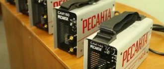
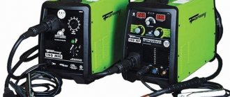
The most common type of privately owned welding equipment is an inverter for performing manual arc welding. How to check its functionality is written in detail in the instructions supplied with it.
For long and successful operation of such a device, you should follow a few simple rules. The load mode of the device should not exceed that recommended in the operating instructions.
The device body and additional accessories (wires, clamps, electrode holder) must be kept clean. The condition of elements subject to wear must be constantly monitored and promptly replaced. This applies to the electrode holder and workpiece clamps.
Periodically, depending on the intensity of use of the product, it is necessary to carry out a maintenance procedure for welding equipment.
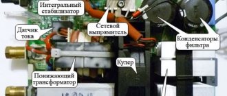
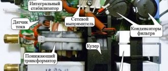
In particular, if this is a welding inverter, you sometimes need to remove the housing cover to remove dust and carbon deposits deposited on the surface of the cooling radiators and electronic components of the circuit.
To do this, you can use a soft brush or blow it with a vacuum cleaner. Dust accumulating inside the housing prevents the normal removal of heat from heating power elements, which can cause their premature failure.
The inverter circuit elements are forcibly cooled by a fan. Cooler maintenance involves cleaning its blades from dust and lubricating the bearings with liquid lubricant.
Technologies, standards, advantages and features of the use of robotic welding
Robotic welding is a fully automated process, which is implemented through the use of special robotic manipulators, welding equipment, fixtures and its workspace. The main advantages of robot welding are the first-class quality of finished products and high productivity of welding production. Like any modern and high-tech production, in the field of robot welding there are a lot of important features, knowledge of which will allow you to achieve the best result and launch a truly safe, highly efficient welding process [1]. The main features of robot welding technology will be discussed in this article.
As already noted, the main advantage of robotic welding is its high accuracy: thus, modern welding robots have technical characteristics that make it possible to achieve accurate positioning of the welding torch with minimum tolerances of the order of 0.03–0.05 mm, which is sufficient for the vast majority of welding tasks.
However, it is necessary to note some drawback of the robot, which is that, unlike a person, if the positioning of the part is not accurate enough, he cannot independently change the trajectory and find the correct point for welding, and in this case the error in positioning and assembling the workpieces should not exceed ± 0.5 mm [2].
To achieve this positioning accuracy, welding path correction methods are used, for example, using a laser seam tracking system. Correction of trajectories makes it possible to ensure high accuracy of the welded product while maintaining quality, but, on the other hand, when using it, a drop in process productivity is expected up to 30% of the manufacturing time.
Thanks to the use of technological equipment, the technological process of welding using robots allows reducing the loss of time for adjusting the welding torch.
Along with this, the welding equipment must fix the workpiece to be welded on the positioning device and provide robots with free access to the welding sites. There is no need to use welding equipment as a tool for editing the geometry of the workpiece being welded before it enters the subsequent automated welding line. An exception may be the use of hydraulic clamps. The essence of using hydraulic clamps is not only to fix, but also to ensure a certain geometry of the workpiece during welding.
Since welding robots are modern, high-precision and high-tech equipment, the workpiece entering the robotic welding operation must meet high requirements for accuracy and quality, which is expressed in the need to use appropriate equipment at all stages preceding welding [2]. The use of modern CNC plasma and laser cutting machines is an excellent solution for cutting metal sheets for subsequent processing by automated welding.
In addition to decent assembly quality of the workpiece and its correct positioning, a prerequisite for accurate assembly and welding by a robot is the calibration of the components of the robot itself. In general, calibration of a robotic complex includes three stages: calibration of axes, including external ones, setting the coordinates of the tool, setting the coordinates of the environment [3].
Axes calibration and environment coordinate adjustment are mandatory. Axle calibration is typically performed once before the system is first started up and is checked regularly during routine maintenance. Tool calibration is necessary to establish a connection between the instrumental and base coordinate systems of the robot manipulator, which, in turn, is required for the correct movement of the torch along a given path, as well as for the accurate operation of the system for correcting these trajectories. The environmental coordinates are necessary to create a virtual model of the complex in a CAM system, which allows you to create welding programs for the robot [3].
Selecting a welding method
The robotic welding method and, accordingly, welding equipment are selected based on the conditions of the production task. Since resistance and electric arc welding are considered the most universal and accessible, our review will be devoted to them.
Arc welding is a process of obtaining the heat necessary for heating and melting metal due to an arc discharge that occurs between the electrode and the metal being welded.
The robotic arc welding system uses uncoated electrode wire as well as flux to protect the arc and weld pool from air. Due to the fact that part of the flux layer, the total thickness of which is 30–35 mm, melts, a gas cavity is formed around the arc and deep penetration of the workpiece metal occurs. During submerged arc welding, on the surface of the molten metal, in addition to the weld pool, a pool of liquid slag is also formed, so when they solidify, the weld becomes covered with a solid slag crust.
Another type of electric arc welding is gas shielded welding, in which the molten metal of the electric arc and weld pool is protected from the effects of atmospheric air by monoatomic argon or helium, neutral diatomic nitrogen or hydrogen, or carbon dioxide.
The advantages of gas shielded welding over submerged arc welding are that it produces a cleaner and visually more beautiful weld without slag inclusions. In addition, gas-shielded arc welding is considered more productive and efficient compared to conventional arc welding.
When resistance spot welding, parts are connected to each other not in a straight line, but pointwise - in one or several places at the same time. The strength of the welded joint is determined by the size and structure of the weld point, which, in turn, depend on the characteristics of the contact surface of the electrode, the strength and time of current flow through the workpiece, the compression force and the quality of the surfaces of the parts.
Workspace organization
The placement and layout of the robot welding complex requires special attention. It is necessary to provide special buffer zones for products after welding. When choosing a location for the welding complex, it is important to remember that the standard requirements for the territory include a high-quality concrete floor, the thickness of which should not be less than 300 mm, with differences not exceeding 5 mm per 1000 mm. In the area where the robotic welding complex is located, it is advisable to design a dry air supply, and when designing the power supply, it is necessary to provide for the use of stabilizers.
Welding cycle control
In order to be able to control the welding cycle, it is important to imagine the entire set of operations of the welding complex and know how long these operations last. It is convenient to organize this data set in the form of a cyclogram, which will allow you to identify bottlenecks in the operation of the welding complex and understand how well this or that operation fits into the production process.
Even at the design stage of a robotic complex, it is necessary to calculate the optimal scheme for its operation, which would minimize robot downtime and be consistent with the actual load of the complex, that is, with the number of workpieces that come from previous production units.
Thus, despite the laboriousness of organizing a welding robot workplace, setting it up, and the significant need for training of personnel programming and servicing the robot, it is necessary to note the following main advantages of modern welding robots over humans:
– increased productivity and welding speed (arc time factor reaches 60–80%);
– reduction in the number of jobs (one welding robot operator replaces 2–4 welders);
– high quality welds;
– improved working conditions (the operator does not need to stand in close proximity to the arc);
– complete safety of welding operators by minimizing the harmful effects of toxic fumes from molten metal, radiation and electric shock;
– reduction of production errors, which means minimizing scrap and rework.
Literature:
- Welding and cutting of metals, M. D. Banov, Yu. V. Kazakov 2006 - 400 p.
- Robotic welding. https://vektor-grupp.ru/articles/1114/
- Robotic welding: application features. https://robo-weld.com/technology/welding_method/robotizirovannaya_svarka_osobennosti_primeneniya.html
Frequency of inspection of welding machines
GOST R IEC 60974-4-2014
NATIONAL STANDARD OF THE RUSSIAN FEDERATION
ARC WELDING EQUIPMENT
Periodic inspection and testing
Arc welding equipment. Part 4. Periodic inspection and testing
OKS 25.160.10* _____________________
* In IUS N 10 2015 GOST R IEC 60974-4-2014 is given with OKS 25.160,
hereinafter. — Note from the database manufacturer.
Date of introduction 2016-01-01
1 PREPARED BY the Federal State Autonomous Institution “Scientific and Educational at MSTU named after N.E. Bauman” (FSAU “NUTSSK at MSTU named after N.E. Bauman”), National Agency for Welding Control (SRO NP “NAKS”), Scientific- production (NPF "ITS"), Limited Liability Company "Storm" (LLC "Storm") based on its own authentic translation into Russian of the standard specified in paragraph 4
2 INTRODUCED by the Technical Committee for Standardization TC 364 “Welding and related processes”
4 This standard is identical to the international standard IEC 60974-4:2010* Arc welding equipment. Part 4: Periodic inspection and testing (IEC 60974-4:2010 Arc welding equipment - Part 4: Periodic inspection and testing). ________________ * Access to international and foreign documents mentioned in the text can be obtained by contacting the User Support Service. — Note from the database manufacturer.
When applying this standard, it is recommended to use instead of reference international standards the corresponding national standards of the Russian Federation and interstate standards, information about which is given in the additional appendix DA.
Degree of Compliance - Identical (IDT)
5 INTRODUCED FOR THE FIRST TIME
The rules for applying this standard are established in GOST R 1.0-2012 (section 8). Information about changes to this standard is published in the annual (as of January 1 of the current year) information index “National Standards”, and the official text of changes and amendments is published in the monthly information index “National Standards”. In case of revision (replacement) or cancellation of this standard, the corresponding notice will be published in the next issue of the information index “National Standards”. Relevant information, notices and texts are also posted in the public information system - on the official website of the Federal Agency for Technical Regulation and Metrology on the Internet (gost.ru)
Basic terms and definitions
Equipment maintenance and repair system - A set of interrelated tools, maintenance and repair documentation and performers necessary to maintain and restore the quality of the products included in this system.
Maintenance of welding equipment (Preventive maintenance, Maintenance) – A set of operations to maintain the serviceability of the equipment.
Repair – A set of operations to restore the serviceability or performance of products.
Frequency of maintenance (repair) - The time interval or operating time between this type of maintenance (repair) and the subsequent type of the same or another of greater complexity. (Note: the type of maintenance (repair) is understood as maintenance (repair), allocated (allocated) according to one of the characteristics: stage of existence, frequency, volume of work, operating conditions, regulation, etc.).
Periodic maintenance – Maintenance performed at operating hours or time intervals established in the operational documentation.
Regulated maintenance – Maintenance provided for in the regulatory, technical or operational documentation and performed at the frequency and to the extent established therein, regardless of the technical condition of the product at the time of the start of maintenance.
Planned maintenance – Maintenance, which is carried out in accordance with the requirements of regulatory, technical or operational documentation.
Overhaul - Repairs performed to restore the serviceability of a product to full or close to full service life with the replacement or restoration of any of its parts, including basic ones.
Medium repair – Repair performed to restore serviceability or partially restore the service life of a product with the replacement or restoration of components of a limited range and monitoring the technical condition of the components.
Medium repair – Repair performed to restore serviceability or partially restore the service life of a product with the replacement or restoration of components of a limited range and monitoring the technical condition of the components.
Scheduled repairs – Repairs that are carried out in accordance with the requirements of regulatory and technical documentation
2.5. Organization of tests. Standards
| GOST | Name |
| 3.1507-84 | ESTD. Rules for preparing documents for testing |
| 20.57.406-81 | Comprehensive quality control system. Products of electronic technology, quantum electronics and electrical engineering. Test methods |
| 27.202-83 | Reliability in technology. Technological systems. Methods for assessing reliability based on quality parameters of manufactured products |
| 27.203-83 | Reliability in technology. Technological systems. General requirements for reliability assessment methods |
| 27.204-83 | Reliability in technology. Technological systems. Technical requirements for methods for assessing reliability using performance parameters |
| 27.410-87 | Reliability in technology. Methods for monitoring reliability indicators and plans for control tests for reliability |
| 16504-81 | System of state testing of products. Testing and quality control of products. Basic terms and definitions |
Requirements of regulatory documents for the maintenance of welding equipment
Operation of welding equipment must be carried out in accordance with the requirements of the “Rules for the technical operation of consumer electrical installations” (RTE).
Requirements of the Rules for the Technical Operation of Consumer Electrical Installations :
- P.1.2.3 To fulfill the responsibilities for organizing the operation of electrical installations, the manager appoints a person responsible for the electrical facilities of the organization;
- Clause 3.1.21 The enterprise must have a system of maintenance and repair of CO (installations), developed and implemented taking into account the operating instructions, operating instructions for CO, instructions from the manufacturer and local conditions;
- Clause 3.1.22 Insulation resistance is measured at least once every 6 months, as well as during long breaks in operation and mechanical damage;
- Clause 1.6.10 Installed equipment must be provided with spare parts and materials. Condition, delivery conditions, storage are controlled by the person responsible for the energy sector
The system of maintenance and repair of welding equipment (WPR) in the organization includes:
- the presence of a person responsible for electrical facilities, who is obliged to provide timely and high-quality technical maintenance and scheduled preventive maintenance (Clause 1.2.6. PTE);
- presence of a person responsible for the operation of welding equipment In accordance with clause 3.1.23 of the PTE in the presence of service Ch. the welder is responsible for him, who “Heads the development of schedules for scheduled maintenance and major repairs of welding equipment”;
- availability of maintenance schedules drawn up by the person responsible for the energy sector, approved by the technical manager of the Consumer (clause 1.6.3. PTE)
PPR schedules should provide for current repairs (maintenance), medium and major. Thus, for sources of general industrial use, the following sequence of scheduled repairs is recommended: start-up (K) – T – S – T – S – T – S – T – K. In this case, the period between repairs is set depending on the complexity of the equipment, operating conditions, intensity work. T - from 3 to 6 months, S - from 1-3 years, K - 3-6 years. So between the repair cycle from one major overhaul to another, the service life of the welding machine is usually 6 years. The passports for individual brands of equipment indicate maintenance periods and scope of work, for example, for the VDU 506, dust is removed and the condition of the contacts is checked once a month, and control units are checked once every 3 months.
In accordance with clause 1.6.7 of the PTE, CO that has reached the service life specified in the passport must undergo technical examination by a commission headed by the technical manager. in order to assess the condition, establish the timing of further work and operating conditions.
The results of the commission’s work must be reflected in the report and technical passports of the welding equipment with a mandatory indication of the period for subsequent examination.
Welding equipment that has reached the service life established by the technical documentation and has not undergone technical diagnostics must be taken out of service. Before decommissioning, it is economical to carry out no more than 1 - 3 major repairs.
Unscheduled repair of a source is prescribed when its inoperable condition is identified
Daily maintenance of the source is performed by the welder before starting work. He inspects the source to identify external damage, checks the presence of grounding, fastening of welding cables and the tightness of gas and water communications. The identified comments are reported to the foreman.
Inspection and preventive maintenance of welding equipment
Maintenance contains operations regulated in the passport or technical documentation to maintain the serviceability of the product throughout its entire service life. Depending on the type of CO, maintenance includes monitoring its technical condition (including measuring insulation resistance), cleaning, lubrication, fastening bolted connections, replacing some wearing parts of the product (for example, feed rollers), adjustment, etc.
To ensure uninterrupted and long-term operation of welding equipment, timely elimination of minor faults during its operation, it is necessary to carry out control and preventive work, which are divided into:
Control and preventive work should be carried out periodically.
For daily maintenance it is necessary:
- Before starting work, inspect the welding equipment to identify accidental damage to individual external parts.
- Check the grounding of the power supply.
- Check the reliability of the connection of the welding wires to the terminals of the power source and the product being welded.
- After starting, check the direction of rotation of the fan, in other words, the correct direction of the cooling air flow.
Monthly (once a month) you need:
- Clean the welding equipment from dust and dirt by blowing the power source with compressed air and wiping in accessible places with a rag.
- Check the condition of electrical wires, mechanical contacts and soldering and, if necessary, ensure reliable electrical contact.
- Check the reliability of all screw connections.
- Check the tightness of the power coils.
- Clean the starter from dust and dirt, check the condition of the contacts. If they are burnt or drops of metal have formed on the surface, then the surface of the contacts must be cleaned.
Once every three months you need:
- Check the insulation resistance of live parts.
- Check the condition of the control unit, the radio interference protection filter of the protective circuits in the required way, and establish the absence of mechanical damage to the capacitors.
- In welding converters, you need to check the condition of the commutator, and if traces of carbon deposits are found on the commutator, it should be sanded with fine-grained sandpaper.
Once every six months you need:
- Clean the contacts and insulating parts of the current range switch from dust and deposits of metal particles.
- Lubricate all rubbing areas with refractory grease.
- In welding converters, check the condition and presence of lubricant in the bearing chambers and, if necessary, replace it.
Once a year you need:
- Disassemble the fan electric motor and clean it internally; before changing the lubricant, the bearings must be washed with gasoline.
- Carry out a routine routine inspection to identify the need for scheduled repairs.
Each enterprise (factory, installation site or site, repair organization) must draw up schedules of inspections, checks, preventive (routine) and major repairs of equipment approved by the chief engineer. In addition to the timing (dates) of control, the schedules indicate the names of the persons responsible for carrying out these operations.
Welding machine VD252
Recommendations for DIY repairs
When repairing inverter-type welding machines, you should adhere to a certain algorithm:
- If a malfunction occurs, you must immediately disconnect the electrical device from the network, allow it to cool, and only then open the metal casing.
- Diagnostics must begin with a visual inspection of the electrical components of the inverter. There are often cases when repairing an inverter welding machine involves simply replacing damaged parts or soldering conductive contacts. Visually enlarged capacitors or cracked transistors should be replaced first.
- If a visual inspection fails to determine the cause of the malfunction of the welding machine, you must proceed to checking the parameters of the parts using a multimeter, voltmeter and oscilloscope. The most common failures of power units are associated with malfunction of transistors.
- After replacing the electrical elements, it is worth moving on to checking the printed conductors located on the inverter board. If you find torn or damaged tracks on the printed circuit board of a welding tool, you must immediately eliminate the defect by soldering jumpers or restoring the tracks using copper wire of the required cross-section.
- After completing work with the tracks, it makes sense to move on to servicing the connectors. If the inverter device stopped working gradually, then there may be poor contact in the connecting connectors. In this case, it is enough to measure all contacts with a multimeter and clean the connectors with an ordinary household eraser.
- Despite the fact that malfunctions of a welding inverter are rarely associated with diode bridges, it would be a good idea to check their performance. It is better to diagnose this electrical element in a soldered state. If all the legs of the bridge are short-circuited, then you should search for the faulty diode and replace it.
- The last step in inverter repair is checking the board and control panels. Diagnostics of all components of the board should be carried out using a high-resolution oscilloscope.
When performing independent repair work, you should not forget about the safety rules:
- Do not use electrical appliances without a protective top casing;
- all diagnostic and repair work should be carried out on completely de-energized equipment;
- It is safest to remove accumulated dust and dirt using an air flow generated by a compressor or a compressed gas cylinder;
- Cleaning of printed circuit boards must be done using neutral solvents applied to a special brush;
- Long-term storage of electrical appliances should be done in dry rooms and completely switched off.
Most inverter electrical appliances are supplied complete with accompanying documentation. In these papers you can find a description of the most common faults and repair methods. Therefore, if malfunctions occur, you should carefully study the documentation and only then begin repair work.
