Power supplies for radio and electrical equipment almost always use rectifiers designed to convert alternating current to direct current. This is due to the fact that almost all electronic circuits and many other devices must be powered from DC sources. A rectifier can be any element with a nonlinear current-voltage characteristic, in other words, passing current differently in opposite directions. In modern devices, planar semiconductor diodes are usually used as such elements.
Planar semiconductor diodes
Along with good conductors and insulators, there are many substances that occupy an intermediate position in conductivity between these two classes. Such substances are called semiconductors. The resistance of a pure semiconductor decreases with increasing temperature, unlike metals, whose resistance increases under these conditions.
By adding a small amount of impurity to a pure semiconductor, its conductivity can be significantly changed. There are two classes of such impurities:
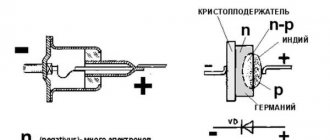
Figure 1. Planar diode: a. diode device, b. designation of a diode in electrical circuits, c. appearance of planar diodes of various powers.
The layer at the interface of p- and n-type semiconductors (pn junction) has one-way conductivity? conducts current well in one (forward) direction and very poorly in the opposite (reverse) direction. The structure of a planar diode is shown in Figure 1a. The basis ? a semiconductor plate (germanium) with a small amount of donor impurity (n-type), on which a piece of indium, which is an acceptor impurity, is placed.
Once heated, indium diffuses into the adjacent regions of the semiconductor, converting them into a p-type semiconductor. A pn junction occurs at the boundary of regions with two types of conductivity. The terminal connected to the p-type semiconductor is called the anode of the resulting diode, the opposite? its cathode. An image of a semiconductor diode on circuit diagrams is shown in Fig. 1b, appearance of planar diodes of various powers? in Fig. 1st century
What is good about the device and what hinders it?
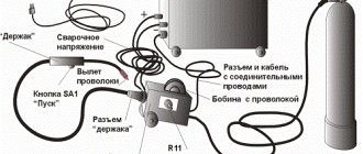
How to convert an AC welding machine into a DC welding machine - the necessary semiconductor circuit with a rectifier device will answer this question for the master:
- The three-phase system has the best performance; it allows you to use network power up to 380 V.
- Such equipment is used where a large continuous process is needed in order to weld large steel parts without interruption during this time period. With the help of these powerful devices you can produce gates, containers, and any utility metal structures.
- Such a tool will be useful mainly not in a private household, but for small businesses and the sale of manufactured products. This is because these are bulky and heavy structures, unlike devices with fewer phases, they require additional installations to move the device.
In such a system, the transformer is capable of reducing weight, but you need to be able to wind its core yourself or buy a ready-made one with the necessary parameters.
The simplest rectifier
Figure 2. Current characteristics in various circuits.
The current flowing in a conventional lighting network is variable. Its magnitude and direction change 50 times within one second. A graph of its voltage versus time is shown in Fig. 2a. Positive half-cycles are shown in red, ? negative.
Since the current value varies from zero to the maximum (amplitude) value, the concept of the effective value of current and voltage is introduced. For example, in a lighting network the effective voltage value is 220 V? in a heating device connected to this network, the same amount of heat is generated over equal periods of time as in the same device in a 220 V DC circuit.
But in fact, the network voltage changes in 0.02 s as follows:
- the first quarter of this time (period)? increases from 0 to 311 V,
- second quarter of the period? decreases from 311 V to 0,
- third quarter of the period? decreases from 0 to 311 V,
- last quarter of the period? increases from 311 V to 0.
In this case, 311 V? voltage amplitude Uо. The amplitude and effective (U) voltages are related to each other by the formula:
When a series-connected diode (VD) and load are connected to an alternating current circuit (Fig. 2b), current flows through it only during positive half-cycles (Fig. 2c). This happens due to the one-way conductivity of the diode. Is such a rectifier called half-wave? During one half of the period there is current in the circuit, during the second? absent.
The current flowing through the load in such a rectifier is not constant, but pulsating. You can turn it almost constant by connecting a filter capacitor Cf of a sufficiently large capacity in parallel with the load. During the first quarter of the period, the capacitor is charged to the amplitude value, and in the intervals between pulsations it is discharged to the load. The tension becomes almost constant. The greater the capacitor capacity, the stronger the smoothing effect.
Problems with a simple power supply with a load
The resistance drawn on the diagram is the equivalent of the load. The load must be such that the current supplying it, with an applied voltage of 12 V, does not exceed 1 A. You can calculate the load power and resistance using the formulas.
Where does the resistance R = 12 Ohm, and the power P = 12 watts come from? This means that if the power is more than 12 watts and the resistance is less than 12 ohms, then our circuit will begin to work with overload, will get very hot and will quickly burn out. There are several ways to solve the problem:
- Stabilize the output voltage so that when the load resistance changes, the current does not exceed the maximum permissible value or when there are sudden current surges in the load network - for example, when some devices are turned on - the peak current values are cut to the nominal value. Such phenomena occur when the power supply powers radio-electronic devices - radios, etc.
- Use special protection circuits that would turn off the power supply if the load current exceeds.
- Use more powerful power supplies or power supplies with more power reserves.
Diode bridge circuit
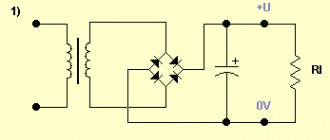
More advanced is the full-wave rectification circuit, when both positive and negative half-cycles are used. There are several varieties of such schemes, but the most commonly used is pavement. The diode bridge circuit is shown in Fig. 3c. The red line on it shows how current flows through the load during positive times, and the blue line? negative half-cycles.
Figure 4. 12 volt rectifier circuit using a diode bridge.
In both the first and second half of the period, the current through the load flows in the same direction (Fig. 3b). The amount of pulsation within one second is not 50, as with half-wave rectification, but 100. Accordingly, with the same filter capacitor capacity, the smoothing effect will be more pronounced.
As you can see, to build a diode bridge you need 4 diodes? VD1-VD4. Previously, diode bridges on circuit diagrams were depicted exactly as in Fig. 3c. The image shown in Fig. 1 is now generally accepted. 3g. Although there is only one picture of a diode, it should not be forgotten that the bridge consists of four diodes.
The bridge circuit is most often assembled from individual diodes, but sometimes monolithic diode assemblies are also used. They are easier to mount on the board, but if one arm of the bridge fails, the entire assembly is replaced. The diodes from which the bridge is mounted are selected based on the amount of current flowing through them and the amount of permissible reverse voltage. This data can be obtained from diode instructions or reference books.
The complete circuit of a 12 volt rectifier using a diode bridge is shown in Fig. 4. T1? step-down transformer, the secondary winding of which provides a voltage of 10-12 V. Fuse FU1? This is a useful detail from a safety point of view and should not be neglected. The brand of diodes VD1-VD4, as already mentioned, is determined by the amount of current that will be consumed from the rectifier. Capacitor C1? electrolytic, with a capacity of 1000.0 μF or higher for a voltage of at least 16 V.
Output voltage? fixed, its value depends on the load. The higher the current, the lower the voltage. To obtain a regulated and stable output voltage, a more complex circuit is required. Obtain the regulated voltage from the circuit shown in Fig. 4 can be done in two ways:
It is hoped that the descriptions and diagrams given above will provide practical assistance in assembling a simple rectifier for practical needs.
There is an inconsistency in electrical engineering. On the one hand, it is more convenient to transmit energy over long distances if it is in the form of alternating voltage. On the other hand, direct current is required to power smartphones, LEDs in light bulbs, circuit boards in TVs and similar household appliances. This problem is successfully solved by a family of radio components such as rectifier diodes.
Mini welding transformer
If you do not need to weld rails or channels from 4–5 mm steel, you can assemble a compact welder for soldering steel wire (making frames for homemade products) or welding thin sheet metal. To do this, you can take a ready-made transformer from a powerful household appliance (the ideal option is a microwave) and rewind the secondary winding. Wire cross-section 15–20 mm², power consumption no more than 2–3 kW.
The calculation of the circuit is carried out in the same way as for more powerful units. When assembling the rectifier, you can use less powerful diodes.
What are diodes
A diode is a semiconductor element based on a silicon crystal. Previously, these parts were also made of germanium, but over time this material was forced out due to its shortcomings. The electrical diode functions as a valve, i.e. it allows current to flow in one direction and blocks it in the other. Such capabilities are built into this part at the level of the atomic structure of its semiconductor crystals.
Read also: Beauty under your feet: making garden paths from a mold
One diode cannot obtain a full constant voltage from an alternating voltage. Therefore, in practice, more complex combinations of these elements are used. An assembly of 4 or 6 parts, combined according to a special circuit, forms a diode bridge. He is already quite capable of coping with full current rectification.
Interesting. Diodes have parasitic sensitivity to temperature and light. Transparent rectifiers in a glass case can be used as light sensors. Germanium diodes (approx. D9B) are suitable as a temperature-sensitive element. Actually, due to the strong dependence of the properties of these elements on temperature, they stopped producing them.
Distinctive features of three-phase equipment
The operating principle of the device, assembled according to an electrical circuit for a rectifier powered by three mains phases, is based on the presence of a small ripple in the output voltage. The waves overlap each other in the process, preventing the voltage from dropping to zero.
The welding installation is constructed by including semiconductors behind the transformer windings in phases. The terminals are connected, resulting in a single output. Through such a bridge, waves divided in two are passed, forming a rapid pulsation, but with less force. In such a design, you will need a zero output, and the transformer is connected to the power supply according to a special circuit.
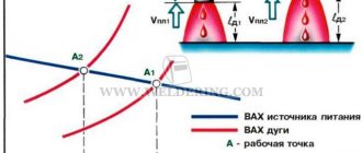
Craftsmen know in practice that the highest quality work is obtained with the use of devices operating on direct current, providing an arc with stable combustion and a durable seam. In order to obtain the necessary parameters, despite the growth of technological discoveries and the emergence of innovations in instrument making, craftsmen with their own hands produce and still use the simplest rectifiers.
Single-phase and three-phase diode bridge
There are two main types of straightening assemblies:
- Single-phase bridge. Most often used in household electrical appliances. Has 4 outputs. Two of them are supplied with alternating voltage, i.e. phase (L) and zero (N). The permanent one is removed from the remaining two, i.e. plus (+) and minus (-).
- Three-phase bridge. It is found in powerful industrial installations and equipment powered by a 380 volt network. Three phases are supplied to its input (L1, L2, L3). The constant voltage is also removed from the output. Such bridges are distinguished by their large size and impressive currents that they are capable of passing through themselves.
Operating principle of a diode bridge
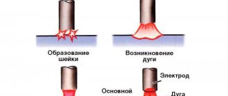
You can understand how a bridge performs its task by understanding how a separate diode behaves. Initially there are only two wires with alternating voltage (L and N). It has the shape of a sinusoid (Fig. a). If you add one diode to the circuit, then it will transmit only the positive half-wave (Fig. b), if this component is deployed, then the negative component (Fig. c). This voltage will no longer be variable. However, it is not suitable for powering serious electrical appliances. There are moments in it when there is no current at all. The use of four diodes will allow you to obtain a constant voltage without any interruptions (Fig. d). Three-phase bridges are straightened using the same method. However, they do this with three sine waves at the same time.
Rectifier
The voltage obtained after the diode bridge has the shape of a sinusoid, in which the negative component is reflected relative to the time axis. In simple terms, it is shaped like hills and is called pulsating. This voltage is positive. Does not contain moments when current does not flow. But it is still unstable. For example, at point “a” it is early 0 volts, and at “b” it has a maximum value. This rectifier cannot be considered complete.
To solve this problem, a smoothing electrolytic capacitor is required. On the board it is usually located in the same place as the diode assembly. The capacitance accumulates energy at those moments when it has peak values (point b), and releases it at moments of dips (a). The output is a straight line - full-fledged direct current, suitable for powering subsequent electronic components, processors, microcircuits, etc.
Application in practice
For example, consider the TELWIN Force 165 inverter device. The input rectifier uses GBPC3508 diode assemblies. The GBPC3508 bridge rectifier can operate with a current of 35 A, reverse voltage - 800 V.
Along with it comes a necessarily smoothing filter made of large capacitors. In addition, there is an electromagnetic compatibility filter that prevents interference from the inverter into the household network.
The output of the inverter uses powerful dual diodes with a common cathode. They have high performance, unlike diodes located at the input of the device.
Thanks to the short recovery time, less than 50 nanoseconds, the devices have time to switch the high-frequency current at the output of the secondary winding.
This device uses dual diodes STTH6003CW, FFH30US30DN or VS-60CPH03, designed for a forward current of 30 amperes for one device (60 amperes for both) and a reverse voltage of 300 volts.
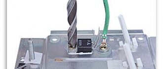
Installed on the radiator. An RC filter is used to protect semiconductors from overload. The control circuit requires a stable power supply without voltage surges.
For this purpose, the device is equipped with zener diodes or a ready-made integrated stabilizer, which provide stable power to the control chips. The result is a compact device that allows high-quality welding of metal.
Disadvantages of a full bridge
A full-fledged full-wave bridge has disadvantages:
- The current is forced to flow not through one diode, but through two at once, connected in series. Therefore, the voltage drop across the rectifier element doubles. For low-power bridges on silicon diodes it can reach 2 volts. In powerful rectifiers - about 10 V. Hence, significant power losses on the rectifying element and its increased heating.
- If one or four diodes fail, the bridge continues to operate. This defect may not be noticeable without special measurements. However, it creates the risk of more serious damage to the device, which is powered through a faulty bridge.
Output voltage regulation
If the power supply voltage needs to be regulated from zero, then the optimal circuit would be a parametric stabilizer with the addition of a variable resistor.
Smooth voltage regulation.
A 1 kOhm resistor connected between the base of the transistor and the common wire will protect the triode from failure if the potentiometer motor circuit breaks. When you rotate the variable resistor knob, the voltage at the base of the transistor will change from 0 to Ust of the zener diode with a lag of approximately 0.6 volts. It must be taken into account that the parameters of the node will be worse due to the use of a potentiometer - the presence of a moving contact (even of good quality) will inevitably reduce the voltage stability at the base of the transistor.
Design
The circuit of any rectifier bridge includes diodes. They can be separately soldered onto a printed circuit board or located in the same housing. Regarding the size, rectifiers are miniature, for example, imported MB6S or Soviet KTs405A. The latter are popularly called “ka-tseshki” or “chocolates”.
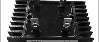
There are samples with impressive dimensions. For example, a three-phase rectifier bridge made in China. The device is designed for currents of hundreds of amperes, therefore it has screw fastening for power wires and a flat metal heat-conducting surface with holes for fixing on the cooling radiator.
Rectifier markings
There are no generally accepted rules according to which manufacturers label their diode bridges. Everyone has the right to name their product as they see fit, i.e. according to its own nomenclature.
However, most of these parts have similar features that help visually determine the purpose of their pins. In the photo of a three-phase bridge (see above), the alternating current symbol is highlighted separately - a wavy line. It indicates that a sinusoidal input voltage is connected to this pin. Also on some bridge models, the input terminals are marked with the letters AC (Alternative Current), indicating alternating current. In this case, the output contacts from which direct current is removed are indicated by the symbols DC (Direct Current) or the traditional “+” and “-”. Additionally, on some rectifiers, one of the corners is “filed” on the plus side. An extended pin can also indicate “+”. This type of marking is common to many electronic components and is called a key.
High Power Power Supply
The power supply can be made more powerful by adding several powerful stages using TIP2955 Darlington transistors to the circuit. One stage will provide an increase in load current of 5 A, six composite transistors connected in parallel will provide a load current of 30 A.
Darlington transistors type TIP2955
A circuit with this kind of power output requires adequate cooling. Transistors must be provided with heat sinks. You may also need an additional cooling fan. In addition, you can protect yourself with fuses (not shown in the diagram).
The figure shows the connection of one composite Darlington transistor, which makes it possible to increase the output current to 5 amperes. You can increase it further by connecting new cascades in parallel with the specified one.
Connecting one composite Darlington transistor
Attention! One of the main disasters in electrical circuits is a sudden short circuit in the load. In this case, as a rule, a current of gigantic power arises, which burns everything in its path. In this case, it is difficult to come up with such a powerful power supply that can withstand this. Then protection circuits are used, ranging from fuses to complex circuits with automatic shutdown on integrated circuits.
DIY diode bridge
To assemble the rectifier yourself, you will need 4 diodes of the same type. At the same time, they must be suitable in terms of reverse voltage, maximum current and operating frequency. Connections must be made in accordance with the diagram below. A positive voltage is removed between the two cathodes and a negative voltage between the anodes. An alternating voltage source is connected to the points at which opposite terminals of the diodes are connected. The entire circuit can be soldered by surface mounting in a couple of minutes, or you can work hard and make it in the form of a small printed circuit board.
Additional Information. The reverse voltages of diodes connected in a series circuit are added to each other.
Selecting a build type
For each task there is its own optimal version of the rectifier diode assembly. All of them can be divided into 3 types:
- Rectifier with one diode. It is used in the simplest and cheapest circuits where there is no c.l. requirements for the quality of the output voltage, as, for example, in night lights.
- Dual diode. These parts look similar to transistors, because they are produced in the same packages. They also have 3 pins. Essentially, these are two diodes placed in one housing. One of the conclusions is average. It can be the common cathode or the anode of the internal diodes.
- Full diode bridge. 4 parts in one case. Suitable for devices with high currents. It is mainly used on the inputs and outputs of various power supplies and chargers.
Additional Information. Rectifiers are also used in cars. They are needed to convert the alternating voltage coming from the generator to direct voltage. This, in turn, is necessary to charge the battery. A conventional gas generator produces alternating current.
Read also: Summer nods - what they should be
Adding a rectifier
A homemade powerful welding transformer from a circuit design point of view is a regular power supply. Accordingly, the rectifier is designed as simply as in a network charger for a mobile phone. Only the element base will look several orders of magnitude more massive.
As a rule, a pair of capacitors are added to a simple diode bridge circuit to dampen rectified current pulses.
You can assemble a rectifier without them, but the smoother the current, the better the quality of the weld. To assemble the bridge itself, powerful diodes of the D161–250(320) type are used. Since a lot of heat is generated on the elements when loaded, it must be dissipated using radiators. The diodes are attached to them using a bolt connection and thermal paste.
Of course, the radiator fins must either be blown by a fan or protrude above the case. Otherwise, instead of cooling, they will heat the transformer.
Checking elements
In most cases, it is not necessary to unsolder the bridge from the board for testing. It should be tested in the same way as a 4 pn junction with a diode bridge connection. This measurement is so common that its capability is implemented in any multimeter. The test device must be switched to diode continuity mode.
The forward voltage drop across a working rectifier diode is 500-700 mV. Otherwise, the device will display “1”. A burnt part most often shows “0” in both directions, i.e. short circuit. Less often, a complete breakage of the element occurs (also in both directions). All measurements should be repeated for each diode included in the bridge. Total 8 measurements, i.e. 4 in forward direction and 4 in reverse. If a Schottky diode is tested, then this parameter is 200-400 mV.
Operating principle of a single-phase bridge circuit
The process of alternating current flow can be represented as a wave oscillating at a certain frequency. This procedure is very fast, which can be imagined as at one specific moment, a current passes first in one direction and then in the other.
In welding, specialists ensure that these movements are carried out unilaterally:
- A semiconductor is soldered into the secondary winding of the transformer; it carries out electrical transmission in the desired direction, which is direct current. Since alternating current has frequencies, its waves will create pauses that are unacceptable in the work process.
- In the circuit, the electrical components are soldered in the opposite direction with respect to each other, then the electron flow will flow in the opposite direction.
- If you create a circuit with pairs of elements directed towards each other, you will get a flow of waves oscillating from zero to maximum. This limit is calculated on the possibility of a secondary transformer winding.
- In the same way, fluctuations are obtained that decrease to a minimum, from the moment of which a new rise begins. In this case, a plus pole voltage is generated, and its minus is located in the transformer winding.
- This circuit is used with an output device in place, so as not to disassemble the winding; it can be created by winding it yourself. This design is famous for its efficiency in relation to the number of semiconductor elements.
- Dividing the winding into several sections allows you to use only part of it.
- The most convenient and applicable for electrical engineers is the bridge rectifier structure. A similar plan consists of a square with semiconductors on the sides. Some of its corners output direct current, others show the voltage output from the transformer.
This example has the advantage that it does not require creating a lead from the second winding, but it will require a lot of semiconductor gates. Welding will be with low power; electrodes of special sizes are selected for them, and parts with limited parameters are welded. It should be taken into account that the parallel connection of a capacitor device reduces wave vibrations during operation of the welding machine.
Using the Schottky barrier
The use of a Schottky diode is justified in two cases. Firstly, when you need to rectify high-frequency current. The Schottky barrier is ideal for such a task, because it has a low junction capacitance and, accordingly, is fast-acting. Secondly, when it is necessary to rectify a large current of tens or hundreds of amperes. In this case, the part performs well due to the low voltage drop and low heat generation.
Diode bridges in the world of electronics play the role of a matching element. With their help, you can connect devices that require direct current to a network of alternating voltage convenient for transmission. There are a lot of such devices in everyday life; they are extremely important for a person’s comfortable life.
The main element used to create a rectifier unit is a diode. Its operation is based on the electron-hole transition (pn).
The generally accepted definition says: a pn junction is a region of space located at the boundary of the junction of two semiconductors of different types. In this space, an n-type to p-type transition is formed. The value of conductivity depends on the atomic structure of the material, namely on how tightly the atoms hold electrons. Atoms in semiconductors are arranged in a lattice, and electrons are bound to them by electrochemical forces. This material itself is a dielectric. It either conducts current poorly or does not conduct it at all. But if atoms of certain elements are added to the lattice (doping), the physical properties of such a material change radically.
Mixed atoms begin to form, depending on their nature, free electrons or holes. The resulting excess electrons form a negative charge, and the holes form a positive charge.
An excess charge of one sign causes carriers to repel each other, while an area with an opposite charge tends to attract them towards itself. An electron, moving, occupies a free space, a hole. At the same time, a hole also forms in its old place. As a result, two flows of charge movement are created: one main and the other reverse. A material with a negative charge uses electrons as majority carriers and is called an n-type semiconductor, while a material with a positive charge using holes is called a p-type semiconductor. In both types of semiconductors, minority charges generate a current opposite to the movement of the main charges.
In radio electronics, germanium and silicon are used from materials to create pn junctions. When crystals of these substances are doped, a semiconductor with different conductivity is formed. For example, the introduction of boron leads to the appearance of free holes and the formation of p-type conductivity. Adding phosphorus, on the other hand, will create electrons and the semiconductor will become n-type.
Add a link to a discussion of the article on the forum
RadioKot >Training >Analog technology >Basics - too simple? That way. Let's continue. >
| Article tags: | Add a tag |
Rectifiers. How and why.
Author: Published 04/20/2006
So, my dears, we have assembled our circuit and it’s time to check it, test it and enjoy this happiness. Next up is connecting the circuit to the power source. Let's get started. We won’t dwell on batteries, accumulators and other power supplies; we’ll move straight to mains power supplies. Here we will look at existing rectification schemes, how they work and what they can do. For experiments we will need single-phase (at home from an outlet) voltage and the corresponding parts. Three-phase rectifiers are used in industry, we will not consider them either. If you grow up to be an electrician, then please.
The power supply consists of several most important parts: Mains transformer - indicated in the diagram as similar to the one in the figure,
Rectifier - its designation may vary. The rectifier consists of one, two or four diodes, depending on which rectifier. Now we'll figure it out.
a) - a simple diode. b) - diode bridge. Consists of four diodes connected as in the figure. c) - the same diode bridge, only drawn simpler for brevity. The contact assignments are the same as for the bridge under letter b).
Filter capacitor. This thing is unchanged in both time and space, and is designated as follows:
There are many designations for a capacitor, as many as there are designation systems in the world. But in general they are all similar. Let's not get confused. And for clarity, let’s draw a load, denote it as Rl - load resistance. This is our scheme. We will also outline the contacts of the power source to which we will connect this load.
Next - a couple of postulates. — The output voltage is defined as Uconst = U*1.41. That is, if we have 10 volts of alternating voltage on the winding, then on the capacitor and on the load we will get 14.1 V. Like that. — Under load, the voltage sags a little, and how much depends on the design of the transformer, its power and the capacitance of the capacitor. — Rectifier diodes should be 1.5-2 times more current than required. For stock. If the diode is intended for installation on a radiator (with a nut or bolt hole), then at a current of more than 2-3A it must be installed on the radiator.
Let me also remind you what bipolar voltage is. If someone has forgotten. We take two batteries and connect them in series. The middle point, that is, the point where the batteries are connected, will be called the common point. It is popularly known as ground, ground, body, common wire. The bourgeoisie call it GND (ground), often referred to as 0V (zero volts). Voltmeters and oscilloscopes are connected to this wire; relative to it, input signals are supplied to the circuits and output signals are taken. That’s why its name is common wire. So, if we connect the tester with the black wire to this point and measure the voltage on the batteries, then the tester will show plus 1.5 volts on one battery, and minus 1.5 volts on the other. This voltage +/-1.5V is called bipolar. Both polarities, that is, plus and minus, must be equal. That is, +/-12, +/-36V, +/-50, etc. A sign of bipolar voltage is if three wires go from the circuit to the power supply (plus, common, minus). But this is not always the case - if we see that the circuit is powered by a voltage of +12 and -5, then such power is called two-level, but there will still be three wires to the power supply. Well, if as many as four voltages are supplied to the circuit, for example +/-15 and +/-36, then we will simply call this power supply - bipolar two-level.
Well, now to the point.
1. Bridge rectification circuit.
The most common scheme. Allows you to obtain unipolar voltage from one winding of the transformer. The circuit has minimal voltage ripple and is simple in design.
2. Half-wave circuit.
Just like the pavement, it prepares us a unipolar voltage from one winding of the transformer. The only difference is that this circuit has double the ripple compared to a bridge circuit, but one diode instead of four greatly simplifies the circuit. It is used for small load currents, and only with a transformer much larger than the load power, because such a rectifier causes one-sided magnetization reversal of the transformer.
3. Full-wave with midpoint.
Two diodes and two windings (or one winding with a midpoint) will supply us with a low-ripple voltage, plus we will get lower losses compared to a bridge circuit, because we have 2 diodes instead of four.
4. Bridge circuit of a bipolar rectifier.
For many, this is a sore subject. We have two windings (or one with a midpoint), we remove two identical voltages from them. They will be equal, the ripples will be small, since the circuit is a bridge circuit, the voltage on each capacitor is calculated as the voltage on each winding multiplied by the root of two - everything is as usual. A wire from the midpoint of the windings equalizes the voltage on the capacitors if the positive and negative loads are different.
5. Voltage doubling circuit.
These are two half-wave circuits, but with diodes connected in different ways. It is used if we need to get double the voltage. The voltage on each capacitor will be determined by our formula, and the total voltage on them will be doubled. Like the half-wave circuit, this one also has large ripples. You can see a bipolar output in it - if you call the middle point of the capacitors ground, then it turns out like in the case of batteries, take a closer look. But you can’t get a lot of power out of such a circuit.
6. Obtaining different polarity voltage from two rectifiers.
It is not at all necessary that these are the same power supplies - they can be either different in voltage or different in power. For example, if our circuit consumes 1A at +12 volts, and 0.5A at -5 volts, then we need two power supplies - +12V 1A and -5V 0.5A. You can also connect two identical rectifiers to obtain a bipolar voltage, for example, to power an amplifier.
7. Parallel connection of identical rectifiers.
It gives us the same voltage, only with double the current. If we connect two rectifiers, we will have a double increase in current, three - triple, etc.
Well, if everything is clear to you, my dears, then I’ll probably give you some homework. The formula for calculating the filter capacitance for a full-wave rectifier is:
For a half-wave rectifier, the formula is slightly different:
The two in the denominator is the number of rectification “cycles”. For a three-phase rectifier, the denominator will be three.
In all formulas, the variables are named as follows: Cf - filter capacitor capacitance, µF Po - output power, W U - output rectified voltage, V f - frequency of alternating voltage, Hz dU - ripple range, V
For reference - permissible ripple: Microphone amplifiers - 0.001...0.01% Digital equipment - ripple 0.1...1% Power amplifiers - ripple of a loaded power supply 1...10% depending on the quality of the amplifier.
These two formulas are valid for voltage rectifiers with a frequency of up to 30 kHz. At higher frequencies, electrolytic capacitors lose their efficiency, and the rectifier is designed a little differently. But that is another topic.
| What do you think of this article? | Did this device work for you? | |
| 75 | 3 | 0 |
| 0 | 2 |
Diode operating principle
A diode is a semiconductor device that has low resistance to current in one direction and prevents it from flowing in the opposite direction. Physically, the diode consists of one pn junction. Structurally, it is an element containing two outputs. The terminal connected to the p-region is called the anode, and the terminal connected to the n-region is called the cathode.
When a diode operates, there are three states:
A forward potential is a signal when the positive pole of the power source is connected to the p-type region of the semiconductor, in other words, the polarity of the external voltage coincides with the polarity of the main carriers. With reverse potential, the negative pole is connected to the p-region and the positive pole to the n region.
There is a potential barrier in the area where the n- and p-type material joins. It is formed by a contact potential difference and is in a balanced state. The height of the barrier does not exceed tenths of a volt and prevents the movement of charge carriers deep into the material.
If direct voltage is connected to the device, then the magnitude of the potential barrier decreases and it practically does not resist the flow of current. Its value increases and depends only on the resistance of the p- and n-regions. When a reverse potential is applied, the barrier value increases, since electrons leave the n-region and holes leave the p-region. The layers become depleted and the barrier's resistance to the passage of current increases.
The main indicator of an element is the current-voltage characteristic. It shows the relationship between the potential applied to it and the current flowing through it. This characteristic is presented in the form of a graph, which indicates the forward and reverse current.
Classic model
Classic stabilizers are a large class of devices assembled based on semiconductor parts such as bipolar transistors and zener diodes. Among them, the main function of maintaining the voltage at 12 V is performed by zener diodes - a type of diodes connected in reverse polarity (the plus of the power supply is connected to the cathode of such a semiconductor device, and the minus to the anode), operating in breakdown mode. The essence of how these semiconductor parts work is as follows:
- When the voltage of the power source connected to the zener diode is less than 12 V, it is in the closed position and does not participate in adjusting this characteristic of the electric current.
- When the threshold of 12 Volts is exceeded, the zener diode “opens” and maintains this value in the range specified by its characteristics.
If the voltage supplied to the zener diode exceeds that stated as the maximum by the manufacturer, the device very quickly fails due to the effect of thermal runaway.
In order for any model of zener diode to serve as long as possible, it is recommended to specify, according to its specification, the voltage range and current strength in which it should be operated.
Depending on the connection, there are two versions of the classic stabilizer: linear - the adjusting elements are connected in series with the load; parallel – voltage stabilizing devices are located parallel to the powered devices.
It’s also important to know: 3 nuances about operation
The homemade product differs somewhat in its method of operation from the factory version. This is explained by the fact that the purchased unit has built-in functions that help with operation. They are difficult to install on a device assembled at home, and therefore you will have to adhere to several rules during operation.
- A self-assembled charger will not turn off when the battery is fully charged. That is why it is necessary to periodically monitor the equipment and connect a multimeter to it to monitor the charge.
- You need to be very careful not to confuse “plus” and “minus”, otherwise the charger will burn out.
- The equipment must be turned off when connecting to the charger.
By following these simple rules, you will be able to properly recharge the battery and avoid unpleasant consequences.
How to make a regulating power supply from a regular printer
We will talk about the power supply for a Canon inkjet printer. Many people have them idle. This is essentially a separate device, held in the printer by a latch. Its characteristics: 24 volts, 0.7 amperes.
We'll get the payment. Such power supplies can be easily converted to the desired voltage and can also be made adjustable. On the reverse side, if we turn it over, there is an adjustable zener diode tl431. On the other hand, we will see the middle contact goes to the base of transistor q51.
If we apply voltage, then this transistor opens and 2.5 volts appears at the resistive divider, which is needed for the zener diode to operate. And 24 volts appears at the output. This is the simplest option. Another way to start it is to throw away transistor q51 and put a jumper instead of resistor r 57 and that’s it. When we turn it on, the output is always 24 volts continuously.
How to make the adjustment?
This option worked out. I installed a variable resistor. The handle turns out to be an adjustable power supply - quite convenient.
Expert opinion
It-Technology, Electrical power and electronics specialist
Ask questions to the “Specialist for modernization of energy generation systems”
How to solder a 12 volt power supply. We make a simple transformer power supply with our own hands. « Electric Hobby This large capacitor, placed at the output of the power supply circuit, is usually called a smoothing capacitor. Ask, I'm in touch!
Simple rectifier circuit
Sinusoidal voltage is a periodic signal that varies over time. From a mathematical point of view, it is described by a function in which the origin corresponds to time equal to zero. The signal consists of two half-waves. The half-wave located in the upper part of the coordinates relative to zero is called a positive half-cycle, and in the lower part - negative.
When an alternating voltage is applied to the diode through a load connected to its terminals, current begins to flow. This current is due to the fact that at the moment the positive half-cycle of the input signal arrives, the diode opens. In this case, a positive potential is applied to the anode and a negative potential to the cathode. When the wave changes to a negative half-cycle, the diode is turned off, as the polarity of the signal at its terminals changes.
Thus, it turns out that the diode, as it were, cuts off the negative half-wave, without passing it to the load, and a pulsating current of only one polarity appears on it. Depending on the frequency of the applied voltage, and for industrial networks it is 50 Hz, the distance between the pulses also changes. This type of current is called rectified, and the process itself is called half-wave rectification.
Read also: Do-it-yourself cages for broiler chickens
By rectifying the signal using a single diode, you can power a load that does not have special requirements for voltage quality. For example, a filament. But if you power up, for example, a receiver, a low-frequency hum will appear, the source of which will be the gap that occurs between the pulses. To some extent, to get rid of the disadvantages of half-wave rectification, a capacitor connected in parallel with the load is used together with a diode. This capacitor will charge when pulses arrive and discharge when there are no pulses to the load. This means that the larger the capacitance value of the capacitor, the smoother the current across the load will be.
But the highest signal quality can be achieved if two half-waves are used simultaneously for rectification. The device that allows this to be realized is called a diode bridge, or in other words, a rectifier bridge.
DIY welding rectifier
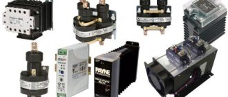
A rectifier for a welding machine is built around semiconductor elements, the essence of which is to pass electrical currents in only one direction. Today, three devices can be used in rectification circuits:
- diode (the best because it is the simplest; when using it, there is no need to introduce control units into the rectifier circuit);
- thyristor (for current to flow, it must receive a signal from the control system; when the passing current drops to zero or the voltage across it becomes less than in the next phase, the valve closes);
- transistor (a fully controllable “valve”, to open and close which you need to send a signal to the control electrode, and also the most expensive element).
Setting the output voltage and charging current
There are two trimming resistors installed on the DC-DC converter board, one allows you to set the maximum output voltage, the other allows you to set the maximum charging current.
Plug in the charger (nothing is connected to the output wires), the indicator will show the voltage at the device output and the current is zero. Use the voltage potentiometer to set the output to 5 volts. Close the output wires together, use the current potentiometer to set the short circuit current to 6 A. Then eliminate the short circuit by disconnecting the output wires and use the voltage potentiometer to set the output to 14.5 volts.
Power supply with stabilizer on a chip
The figure below shows the development of the previous simple circuit by including a 12-volt stabilizer LM7812 at the output of the microcircuit.
Power supply with stabilizer on a chip
This is already better, but the maximum load current of such a stabilized power supply unit should still not exceed 1 A.
Diode bridge
Such a device is an electrical device used to convert alternating current into direct current. The phrase “diode bridge” is formed from the word “diode”, which implies the use of diodes in it. The diode bridge rectifier circuit depends on the AC network to which it is connected. The network can be:
Depending on this, the rectifier bridge is called a Graetz bridge or a Larionov rectifier. In the first case, four diodes are used, and in the second, the device is assembled using six.
The first rectifier circuit was assembled using radio tubes and was considered a complex and expensive solution. But with the development of semiconductor technology, the diode bridge has completely replaced alternative methods of signal rectification. Selenium pillars are rarely used instead of diodes.
Device designs and characteristics
Structurally, the rectifier bridge is made of a set of individual diodes or a cast housing with four terminals. The body can be flat or cylindrical. According to the accepted standard, icons on the device body mark the terminals for connecting alternating voltage and the output constant signal. Rectifiers with a housing with a hole are designed for mounting on a radiator. The main characteristics of the rectifier bridge are:
- Highest forward voltage . This is the maximum value at which the device parameters do not go beyond the permissible limits.
- Highest permissible reverse voltage . This is the maximum pulse voltage at which the bridge operates for a long time and reliably.
- Maximum operating rectification current . Indicates the average current flowing through the bridge.
- Maximum frequency . The frequency of voltage supplied to the bridge at which the device operates efficiently and does not exceed the permissible heating.
Exceeding the rectifier's characteristics leads to a sharp reduction in its service life or breakdown of pn junctions. It should be noted that all diode parameters are indicated for an ambient temperature of 20 degrees. The disadvantages of using a bridge rectification circuit include a higher voltage drop compared to a half-wave circuit and a lower efficiency value. To reduce losses and reduce heating, bridges are often made using fast Schottky diodes.
Device connection diagram
On electrical circuits and printed circuit boards, a diode rectifier is indicated by a diode icon or in Latin letters. If the rectifier is assembled from individual diodes, then next to each is placed the designation VD and a number indicating the serial number of the diode in the circuit. VDS or BD labels are rarely used.
The diode rectifier can be connected directly to a 220 volt network or after a step-down transformer, but its connection circuit remains unchanged.
When a signal arrives in each half-cycle, current will only be able to flow through its own pair of diodes, and the opposite pair will be blocked for it. For a positive half-cycle, VD2 and VD3 will be open, and for a negative half-cycle, VD1 and VD4. As a result, the output will be a constant signal, but its pulsation frequency will be doubled. In order to reduce the ripple of the output signal, a parallel connection of capacitor C1 is used, as in the case of one diode. Such a capacitor is also called a smoothing capacitor.
But it happens that the diode bridge is placed not only in an alternating network, but is also connected to an already rectified one. Why a diode bridge is needed in such a circuit will become clear if you pay attention to which circuits use such a connection. These circuits involve the use of radioelements that are sensitive to power reversal. Using a bridge allows for simple but effective foolproof protection. In case of incorrect connection of the power polarity, the radio elements installed behind the bridge will not fail.
Functionality check
This type of electronic device can be checked without desoldering it from the circuit, since no shunting is used in the device designs. In the case of a rectifier assembled from diodes, each diode is checked separately. And in the case of a monolithic case, measurements are carried out on all four of its terminals.
The essence of the test comes down to checking the diodes for a short circuit with a multimeter. To do this, perform the following steps:
- The multimeter switches to diode or resistance vertebrae mode.
- The plug of one wire (black) is inserted into the common socket of the tester, and the second (red) into the resistance test socket.
- With the probe connected to the black wire, touch the first leg, and with the probe of the red wire, touch the third pin. The tester should show infinity, and if you change the polarity of the wires, the multimeter will show the transition resistance.
- The minus of the tester is fed to the fourth leg, and the plus to the third. The multimeter will show resistance; when changing polarity, infinity.
- Minus on the first leg, plus on the second. The tester will show an open transition, and when changing, a closed one.
Such tester readings indicate the serviceability of the rectifier. If you don't have a multimeter, you can use a regular voltmeter. But in this case you will have to supply power to the circuit and measure the voltage on the smoothing capacitor. Its value should exceed the input value by 1.4 times.
Popular posts
- DIY Easter egg for Easter 2022 - 5 best crafts 12 volt DC motor speed controller How to make a boat out of foam How to make welding pliers for spot welding How to build a horse stable Papercraft for beginners, paper modeling, 3D sculptures and simple paper figures for children How to make a bouquet in a box with your own hands: step-by-step instructions Drip irrigation in a greenhouse and in the garden with your own hands
Inverter welding rectifier: let's look at what's what
The operating diagram of the inverter device is slightly different than the classic one. Instead of a step-down transformer, an electronic filter is installed at its input, which converts the frequency of the incoming electric current from 50 Hz to several tens of kHz. Afterwards a step-down transformer is installed, and only then a rectifier bridge. The advantages of such welding machines are their low weight compared to conventional ones. This is achieved due to the fact that the magnetic core of the high-frequency transformer has smaller weight and dimensions.
Rectifiers for inverter welding machines are built on the basis of thyristors, with a pulse-phase control system. Next, as expected, a capacitor is connected to the welding circuit, parallel to the load, and a rheostat and a choke are connected in front of the welding electrode. The disadvantage of the rectifiers under consideration is the amount of electronics; it is almost impossible to assemble it yourself, as well as to repair it. Single-station welding rectifiers with good rectified current performance can be assembled at home if all the necessary components are available, and this is a worthy alternative to buying a new rectifier.
- Author: Mikhail Malofeev
Rate this article:
- 5
- 4
- 3
- 2
- 1
(0 votes, average: 0 out of 5)
Share with your friends!