Design and principle of operation
The functioning of a forging hammer is based on the dynamic impacts of the working body - the rod, connected to the head (the striking part of the machine) and devices that control the force of impact. Other required structural elements are:
- a piston connected to a woman;
- base (fixed on a solid surface);
- bed (guides for moving units are fixed on it);
- drive equipment;
- shield fence (for operator safety);
- electrical equipment;
- compressor cylinder (for pneumatic hammers).
Early machines were either foot or hand driven. A modern forging hammer is equipped with a convenient control system that minimizes the effort of the forge worker.
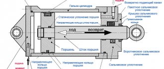
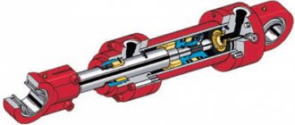
Rice. 1. Pneumatic hammer device.
(1 - working cylinder, 2 - compressor cylinder, 3 - piston, 4 - crank mechanism, 5 - woman, 6 and 7 - upper and lower strikers, 8 - cushion, 9 - air distribution mechanism, 10 - deformable workpiece)
Briefly, the device works like this:
- the workpiece is placed in the lower part of the hammer (usually the hammer);
- set the device to a certain impact frequency and set it in motion;
- after activating the hammer, the driven upper part hits the workpiece;
- the dynamic effect continues until the workpiece acquires the desired shape.
When a forging hammer operates, the reciprocating movement of the crank mechanism is converted into the same movement of the piston. This allows you to perform many operations on it.
Basic information about hammer design
STUDYING THE DESIGN AND CERTIFICATION OF THE DRIVE
FORGING PNEUMATIC HAMMER
Goal of the work:
studying the design and operation of a driven forging pneumatic hammer, determining its basic passport data, gaining skills in drawing up a passport for a pneumatic hammer.
Basic information about hammer design
Driven pneumatic hammers are designed to perform various forging works carried out by forging: broaching, upsetting, piercing holes (through and blind), cutting, bending, forge welding, etc. On pneumatic hammers, stamping in backing dies is possible. Stamping in closed dies is unacceptable, since the harshness of the blows can lead to breakage of the die.
Driven pneumatic hammers (Fig. 1.1) operate using air supplied from the surrounding atmosphere into the compressor cylinder 6 and subjected to compression and discharge during the reciprocating movement of the compressor piston 8. The compressor piston 8 is driven by the drive electric motor 1 through a V-belt drive 2, gearbox 3, crank 4 and connecting rod 5. It should be noted that in the kinematic chain of the electric motor-piston compressor there may not be a gearbox. In this case, the connecting rod 5 is connected to the crank shaft, on which the flywheel is rigidly mounted. The gearbox is necessary to reduce the crank speed.
The following designations are introduced in Fig. 1.1: 1 – drive electric motor; 2 – V-belt drive; 3 – helical gearbox; 4 – crank shaft; 5 – connecting rod; 6 – compressor cylinder; 7 – working cylinder; 8 – compressor piston; 9 – piston of the working cylinder; 10 – air distribution mechanism; 11 – hammer frame; 12 – woman; 13, 14 – upper and lower striker; 15 – shabot; 16 – vibration isolation of the chabot.
According to the principle of operation, pneumatic hammers differ from steam-air hammers, in which the falling parts are accelerated under the action of steam or compressed air entering the working cylinder. For pneumatic hammers, as can be seen from Fig. 1.1, the air provides only a non-rigid connection between the compressor 8 and working 9 pistons, being an elastic cushion that transmits movement from the compressor piston 8 to the working piston 9. The number of hammer blows per minute is equal to the number of revolutions of the crank 4.
a – general view; b – layout diagram of control handles
air distribution mechanism (1-3 – handle positions)
Figure 1.1 – Design of driven pneumatic hammers
The upper movable striker 13 is fixed to the head 12, and the lower fixed striker 14 is attached to the striker 15.
Pneumatic hammers are produced with a mass of falling parts (MPM) of 50...1000 kg and with an impact energy of 0.8...28 kJ. The speed at the moment of impact can be 5...7.5 m/s. The mass multiplicity is 12.
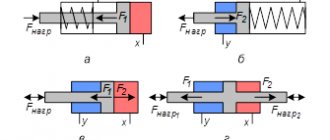
The movement of the compressor piston is a movement with one degree of freedom, determined by the crank angle (Fig. 1.2). The working piston is in the lowest position; in this case, the firing pin is on the forging, and the compressor piston is in the highest position (Fig. 1.2, a
). In this position, the upper and lower cavities of the compressor cylinder are connected to the atmosphere, and the initial pressure in them is set equal to atmospheric pressure. The same pressure is established in the upper and lower cavities of the working cylinder, since these cavities communicate through taps with the corresponding cavities of the compressor cylinder.
a – initial position; b – upward movement of the working piston;
c – downward movement of the working piston
Figure 1.2 – Scheme of movement of the pistons of the working and compressor cylinder
When the piston of the compressor cylinder moves downward from the initial position, the pressure in the lower cavities of both cylinders increases, and in the upper cavities it decreases. When the pressure in the lower cavities increases to a value sufficient to overcome the force of gravity of the moving parts, frictional resistance and air pressure in the piston cavity of the working cylinder, the working piston will begin to move upward. At the crank rotation angle a2 = p, when the compressor piston takes the lower position, the upper cavity of the compressor cylinder is connected to the atmosphere (Fig. 1.2, b
). At this moment, the lower cavity of the compressor cylinder is not connected to the atmosphere.
At a certain angle of rotation of the crank, the upper piston, rising upward, will close the upper channel and disconnect the upper cavities of the cylinders (Fig. 1.2, c
).
As a result, the stroke of the working piston will begin to slow down, and at some point the working piston will stop in its upper position. In this case, the air in the above-piston cavity of the working piston will be compressed. When the working piston is lowered, the pressure in the above-piston cavity will decrease, and at the moment when it becomes equal to the pressure in the upper cavity of the compressor cylinder, both cavities will be connected through a check valve. The angle a4 at which this occurs is called the exit angle of the working piston from the buffer
.
With further rotation of the crank, the compressor piston approaches its uppermost position, and the working piston approaches its lowest position.
The impact of the striker on the forging usually occurs at a crank angle that is slightly less than 2p. In Fig. Figure 1.3 shows a general view of the studied pneumatic drive hammer model MA4127 with a 50 kg weight capacity.
1 – compressor cylinder; 2 – working cylinder; 3 – handle of the middle tap; 4 – handle of the upper and lower valves; 5 – drive electric motor; 6 – V-belt drive casing; 7 – hammer frame; 8 – crank shaft axis; 9 – working strikers; 10 – control pedal
Figure 1.3 – General view of the studied drive pneumatic hammer
models MA4127 with 50 kg MPC
The structure of the hammer under study is similar to the design shown in Fig. 1.1, with the only difference that in its design there is no gearbox (the connecting rod is driven through a V-belt drive, a flywheel and a crank shaft) and the chabot is installed directly in the frame. The installation of a chabot in the hammer frame is possible due to the smallness of the MF, and, consequently, the impact energy.
Pneumatic hammers can carry out the following operating modes: idling, holding the hammer in weight, automatic sequential blows and pressing the forging. Some hammer designs have a single strike mode. To implement the above modes on pneumatic hammers, an air distribution mechanism is used, consisting of three horizontal valves (see Fig. 1.1, b
): upper, middle and lower. The upper and lower valves are used to control the operation of the hammer, and the middle one is used to switch the compressor to idle. Between the upper and lower taps in the hammer shell there is a chamber with a check valve.
In Fig. Figure 1.4 shows a detailed diagram of the air distribution mechanism of pneumatic hammers. The upper valve has two sections, and the lower one has three.
Figure 1.4 – Expanded diagram of the air distribution mechanism
pneumatic hammers
Idling
To avoid overheating the compressor during long pauses, it is switched to idle operation. This is done by turning the middle tap to the extreme left position (the tap is open) (see Fig. 1.3, item 3), while the handles of the upper and lower taps are in the middle position (the pedal is also in the middle position).
As a result, the upper cavity of the working cylinder and the upper cavity of the compressor cylinder communicate through the upper valve with the atmosphere through open channel 3 (see Fig. 1.4). The lower cavity of the compressor cylinder also (through the middle valve) communicates with the atmosphere through open channel 4 (at the same time, channels 10 and 11 are also open).
Thus, the compressor works, but the pressure in the cavities of the working and compressor cylinders is equal to atmospheric pressure, and the woman, under her own weight, rests on the lower striker. The hammer is running idle.
STUDYING THE DESIGN AND CERTIFICATION OF THE DRIVE
FORGING PNEUMATIC HAMMER
Goal of the work:
studying the design and operation of a driven forging pneumatic hammer, determining its basic passport data, gaining skills in drawing up a passport for a pneumatic hammer.
Basic information about hammer design
Driven pneumatic hammers are designed to perform various forging works carried out by forging: broaching, upsetting, piercing holes (through and blind), cutting, bending, forge welding, etc. On pneumatic hammers, stamping in backing dies is possible. Stamping in closed dies is unacceptable, since the harshness of the blows can lead to breakage of the die.
Driven pneumatic hammers (Fig. 1.1) operate using air supplied from the surrounding atmosphere into the compressor cylinder 6 and subjected to compression and discharge during the reciprocating movement of the compressor piston 8. The compressor piston 8 is driven by the drive electric motor 1 through a V-belt drive 2, gearbox 3, crank 4 and connecting rod 5. It should be noted that in the kinematic chain of the electric motor-piston compressor there may not be a gearbox. In this case, the connecting rod 5 is connected to the crank shaft, on which the flywheel is rigidly mounted. The gearbox is necessary to reduce the crank speed.
The following designations are introduced in Fig. 1.1: 1 – drive electric motor; 2 – V-belt drive; 3 – helical gearbox; 4 – crank shaft; 5 – connecting rod; 6 – compressor cylinder; 7 – working cylinder; 8 – compressor piston; 9 – piston of the working cylinder; 10 – air distribution mechanism; 11 – hammer frame; 12 – woman; 13, 14 – upper and lower striker; 15 – shabot; 16 – vibration isolation of the chabot.
According to the principle of operation, pneumatic hammers differ from steam-air hammers, in which the falling parts are accelerated under the action of steam or compressed air entering the working cylinder. For pneumatic hammers, as can be seen from Fig. 1.1, the air provides only a non-rigid connection between the compressor 8 and working 9 pistons, being an elastic cushion that transmits movement from the compressor piston 8 to the working piston 9. The number of hammer blows per minute is equal to the number of revolutions of the crank 4.
a – general view; b – layout diagram of control handles
air distribution mechanism (1-3 – handle positions)
Figure 1.1 – Design of driven pneumatic hammers
The upper movable striker 13 is fixed to the head 12, and the lower fixed striker 14 is attached to the striker 15.
Pneumatic hammers are produced with a mass of falling parts (MPM) of 50...1000 kg and with an impact energy of 0.8...28 kJ. The speed at the moment of impact can be 5...7.5 m/s. The mass multiplicity is 12.
The movement of the compressor piston is a movement with one degree of freedom, determined by the crank angle (Fig. 1.2). The working piston is in the lowest position; in this case, the firing pin is on the forging, and the compressor piston is in the highest position (Fig. 1.2, a
). In this position, the upper and lower cavities of the compressor cylinder are connected to the atmosphere, and the initial pressure in them is set equal to atmospheric pressure. The same pressure is established in the upper and lower cavities of the working cylinder, since these cavities communicate through taps with the corresponding cavities of the compressor cylinder.
a – initial position; b – upward movement of the working piston;
c – downward movement of the working piston
Figure 1.2 – Scheme of movement of the pistons of the working and compressor cylinder
When the piston of the compressor cylinder moves downward from the initial position, the pressure in the lower cavities of both cylinders increases, and in the upper cavities it decreases. When the pressure in the lower cavities increases to a value sufficient to overcome the force of gravity of the moving parts, frictional resistance and air pressure in the piston cavity of the working cylinder, the working piston will begin to move upward. At the crank rotation angle a2 = p, when the compressor piston takes the lower position, the upper cavity of the compressor cylinder is connected to the atmosphere (Fig. 1.2, b
). At this moment, the lower cavity of the compressor cylinder is not connected to the atmosphere.
At a certain angle of rotation of the crank, the upper piston, rising upward, will close the upper channel and disconnect the upper cavities of the cylinders (Fig. 1.2, c
).
As a result, the stroke of the working piston will begin to slow down, and at some point the working piston will stop in its upper position. In this case, the air in the above-piston cavity of the working piston will be compressed. When the working piston is lowered, the pressure in the above-piston cavity will decrease, and at the moment when it becomes equal to the pressure in the upper cavity of the compressor cylinder, the two cavities will be connected through a check valve. The angle a4 at which this occurs is called the exit angle of the working piston from the buffer
.
With further rotation of the crank, the compressor piston approaches its uppermost position, and the working piston approaches its lowest position.
The impact of the striker on the forging usually occurs at a crank angle that is slightly less than 2p. In Fig. Figure 1.3 shows a general view of the studied pneumatic drive hammer model MA4127 with a 50 kg weight capacity.
1 – compressor cylinder; 2 – working cylinder; 3 – handle of the middle tap; 4 – handle of the upper and lower valves; 5 – drive electric motor; 6 – V-belt drive casing; 7 – hammer frame; 8 – crank shaft axis; 9 – working strikers; 10 – control pedal
Figure 1.3 – General view of the studied drive pneumatic hammer
models MA4127 with 50 kg MPC
The structure of the hammer under study is similar to the design shown in Fig. 1.1, with the only difference that in its design there is no gearbox (the connecting rod is driven through a V-belt drive, a flywheel and a crank shaft) and the chabot is installed directly in the frame. The installation of a chabot in the hammer frame is possible due to the smallness of the MF, and, consequently, the impact energy.
Pneumatic hammers can carry out the following operating modes: idling, holding the hammer in weight, automatic sequential blows and pressing the forging. Some hammer designs have a single strike mode. To implement the above modes on pneumatic hammers, an air distribution mechanism is used, consisting of three horizontal valves (see Fig. 1.1, b
): upper, middle and lower. The upper and lower valves are used to control the operation of the hammer, and the middle one is used to switch the compressor to idle. Between the upper and lower taps in the hammer shell there is a chamber with a check valve.
In Fig. Figure 1.4 shows a detailed diagram of the air distribution mechanism of pneumatic hammers. The upper valve has two sections, and the lower one has three.
Figure 1.4 – Expanded diagram of the air distribution mechanism
pneumatic hammers
Idling
In order not to overheat the compressor during long pauses, it is switched to idle operation. This is done by turning the middle tap to the extreme left position (the tap is open) (see Fig. 1.3, item 3), while the handles of the upper and lower taps are in the middle position (the pedal is also in the middle position).
As a result, the upper cavity of the working cylinder and the upper cavity of the compressor cylinder communicate through the upper valve with the atmosphere through open channel 3 (see Fig. 1.4). The lower cavity of the compressor cylinder also (through the middle valve) communicates with the atmosphere through open channel 4 (at the same time, channels 10 and 11 are also open).
Thus, the compressor works, but the pressure in the cavities of the working and compressor cylinders is equal to atmospheric pressure, and the woman, under her own weight, rests on the lower striker. The hammer is running idle.
Forging machine capabilities
The dimensional hammer is designed to perform the following blacksmith operations:
- bending parts (sometimes the workpiece is preheated);
- drawing (extension of the template by reducing the cross section);
- making holes (a punch/piercing is placed on the rod);
- sediment (reverse action to drawing);
- chopping (using axes).
Some of them are clear.
Rice. 2. Operations performed using a forging hammer.
Most well-known products perform all of the above operations. However, there is an important criterion for their classification.
Hammer assembly and installation
The accuracy of the hammer's operation largely depends on its correct installation (Fig. Installation drawing
). The depth of the foundation depends on the quality of the soil, groundwater level and other local conditions.
Foundation parts are not supplied by the factory.
The lining under the chabot is made from planed beams of dried hardwood (beech, oak). Installation of the chabot on the gasket is carried out according to the level. The deviation from horizontality of the supporting plane of the groove in the cushion should not exceed 0.2 mm over a length of 1000 mm.
After installing the chabot on a layer of beams and aligning the strikers, 2 pieces of beams are laid along the contour of the base of the chabot. from each side. For vibration isolation, inert materials (slag, etc.) are poured between the chabot and the walls of the pit.
The hammer is aligned so that the deviation of the hammer from the vertical position is no more than 2 mm over a length of 1000 mm and the tightness of the contact of the working planes of the strikers in contact does not exceed 0.2 mm per 300 mm of the length and width of the striker.
The chabot must be installed so that the ring mark on the woman is 5-10 mm higher than the lower end of the axle box. After running-in as a result of the settlement of the chabot, the annular mark should coincide with the lower edge of the axlebox, which corresponds to the normal relative position of the chabot and the woman. In the future, you must strictly monitor the correct position of the ring marks.
After filling the wells of the foundation bolts and hardening of the concrete solution, drive counter oak wedges between the frame and the chabot (the slope of the wedges is 2°), you should once again check the installation of the strikers and then finally tighten the nuts of the anchor bolts.
Main details of the foundation (Name/Material, GOST/Quantity):
Beams 130x130x780 Oak (beech), GOST 8486-66. 6 pieces Bars 40x40x740. Oak (beech), GOST 8486-66. 4 pcs Wedges 30x80x280. Oak, GOST 8486-66. 52-62 pcs Pipes d (ø) 125x1300. GOST3262-75. 6 pcs Bolts M30x1380. Steel 35, GOST 1050-74. 6 pcs Bolts M20x450. Steel 35, GOST 1050-74. 4 pcs Nuts M30-6N.56.05. GOST 5927-70. 12 pcs Washers 10x80x100. Steel St.3, GOST 380-71. 6 pcs Washers 90x10. Steel St.3, GOST 380-71. 6 pcs Nuts M20-6N.56.05. GOST 5927-70. 4 pcs Washers 20. GOST 11371-68. 4 things
Installation drawing
Types of devices
This criterion is the type of substance used in the compressor cylinder. Hammers are distinguished:
Rice. 3. Mechanical forging hammer with foot drive.
- steam-air (steam or atmospheric air);
- hydraulic and hydrostatic (fluid under pressure);
- gasoline (work on the principle of internal combustion engines);
- gas (liquefied gas);
- electromagnetic (the energy of electric and magnetic fields is used);
- mechanical (powered by human physical effort);
- spring-spring (the spring accelerates the fall of the piston down);
- pneumatic (gas under pressure).
Among the listed devices, the forging pneumatic hammer stands apart. It has its own pneumatic cylinder, which eliminates the need to use additional energy sources and make the structure heavier. More details about the devices below.
Features of pneumatic hammers
The equipment refers to forging devices that perform all the previously listed operations, as well as twisting, cutting and shaping of workpieces.
They are controlled by hand lever or pedal. Structurally, the forging pneumatic hammer is complemented by an oil pump that lubricates the working cylinders (of which, by the way, there can be two). Conventionally, pneumatic hammers are divided into 2 groups:
- for artistic forging (models with a mass of falling parts up to 75 kg);
- for production (MPF - from 150 to 2000 kg).
The advantages of the equipment are energy intensity, sensitivity of adjustment of operating modes, ease of control, and durability. The disadvantage is the large size and weight, but the need for transportation rarely arises.