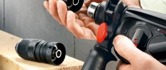
5 How to change brushes: work in a few minutes Unfortunately, the drill may not work due to obvious defects - for example, due to brushes inside the motor. This means that there is no way to do this without repairing the brushes; at the same time, this work is quite ordinary - you don’t even need to have any special knowledge or tools. For this purpose, we disassemble the device, remove the brush holders using it and replace parts that are broken. By the way, there are models whose body has the option of not disassembling - here you just need to remove special plugs through the installation window, then change the brushes.
You see, there are various breakdowns, probably where they will be subordinated to you, others will only be feasible for specialists in service centers. And in order to reduce the risk of such breakdowns, you need to take care of your tool, clean it after work, inspect the condition of the parts and brushes so that it’s time to replace them with new ones. But if you see that you can’t control it yourself, take the device to the workshop.
How to Connect a Screwdriver Button
A screwdriver is a mobile tool that makes it easier to work with fasteners and threaded connections.
Previously, you could only find cordless screwdrivers in the arsenal of experts, but when cheap household models became widely available, their popularity has increased sharply.
In contrast to expensive professional tools, economical analogues have the least resource, which is why they often fall into disrepair.
One of the weakest points of a household screwdriver is the start button and reverse switch. Practice shows that they break down in most cases.
You, our client is left with the fact that all additional parts are removed from the door, the soft start function stops working, and then a stronger pull on the “trigger” is required to start the electric motor.
Over time, the instrument completely stops responding to any manipulation. Often there is a problem of the opposite nature, when the motor begins to work spontaneously.
Sometimes, to eliminate the defect, it is enough to disassemble the tool and clean it, although more often a complete change of the screwdriver button . In both the first and second cases, you can remove the problem on your own. About many things in order.
The screwdriver button is the main control point, which performs several functions at once:
- Switching on/on the tool;
Switching direction of rotation;
Here, any of the control parts integrated into the button block are not actually able to work correctly. Not counting the rotation direction switch, which is often a very multifunctional unit.
The case almost always consists of 3 conventional compartments, in which working units and mechanisms are located.
- At the bottom of the housing there is a control unit for turning on/off and adjusting the speed of the electric motor.
- The soft start “trigger” itself is located in the middle part (the deeper it is pressed in, the higher the rotation speed of the cartridge). When pressed, the button slides in a special block along the guides; a variable resistor is responsible for adjusting the speed.
- In the upper part there is a reverse button - a switch for the direction of rotation of the cartridge. The direction changes due to a change in the polarity of the voltage supplied to the switch.
This is roughly how the control units of screwdrivers of various brands are arranged for our client. To study the button structure of a certain tool model in more detail, we recommend studying the diagram of the screwdriver button (it is, of course, in the annotation).
To diagnose and repair a screwdriver, the following tools will be useful:
- Crosshead screwdriver;
- Screwdriver with a narrow flat slot.
During active use of any power tool, dirt inevitably accumulates inside its body.
Getting into the control unit, it prevents the real movement of the “trigger” and blocks it.
Stages of diagnostics:
- We disassemble the tool body. For this purpose, we disconnect the battery, unscrew it, and our client is left with the screws (they will be hidden behind decorative trims that will have to be removed).
- We check the serviceability of the electric motor. For this purpose, we disconnect two power wires from the control unit and connect them to the battery contacts (the engine should start working).
- We disassemble the screwdriver button. For this purpose, it is necessary to press out the plastic latches and separate the two parts of the button body.
- We visually inspect the condition of the button for dirt and damage.
- Next, you need to carefully assemble the screwdriver button, install it at its destination and test it.
If cleaning the control unit does not produce results, you need to replace the entire button unit.
- Disassemble the screwdriver (the process is described above);
- Install the new button at the destination of the old one;
- Connect the motor to the button terminals (maintaining polarity in our version is not necessary);
- Assemble the screwdriver, carefully placing the wires in the housing.
It is important to select a button for a specific screwdriver model, since despite all the external similarity and visual agreement, the part may not fit into the grooves. You, new buttons are sold complete with battery terminals and transistor.
Screwdriver speed controller
An electric screwdriver operates either from a 220 V network or from a rechargeable battery. Its power depends on the battery voltage. The screwdriver rotation speed starts at 15,000 rpm. In addition, a powered screwdriver has 2 rotation speeds: a slower one for screwing, a higher one for drilling. The speed control is located inside the power button. The rather miniature size of this tool assembly is achieved using microfilm technology. Its main part is a triac. The operating principle of the regulator is as follows:
- When the button is turned on, an alternating current having a sinusoidal phase is supplied to the control electrode of the triac.
- The triac opens and current begins to pass through the load.
The response time of the triac depends on the amplitude of the control voltage. The greater the amplitude, the earlier the triac is triggered. The amplitude value is set using a variable resistor connected to the start button. The button connection diagram differs in different models. It is possible to connect a capacitor to the speed controller.
Often, in the current economic conditions, the buyer cannot always afford a full-fledged expensive screwdriver from reputable companies. Cheaper models may not have this feature. But this is no reason to despair. You can assemble the speed controller yourself, which we will talk about below.
The screwdriver speed controller is assembled on the basis of a PWM controller and a key multi-channel field-effect transistor. The operation of this tool unit is controlled by a resistor. Its position depends on the pressure on the screwdriver start button.
The direction of rotation of the working body changes by changing the poles of the voltage that is supplied to the motor brushes. This is done instrumentally using changeover contacts actuated by a reverse lever.
It is possible to assemble such a regulator with your own hands. We will look at how to do this below.
A diagram of the elements that make up the speed controller is shown in the figure below.
Scheme
In this case, a dual comparator microcircuit LM 393 is used. Here, the first comparator works as a sawtooth voltage generator, and the second one is PWM. The control signal for PWM is the voltage drop across the motor contacts. To put it simply, in the diagram the electric motor looks like active and inductive resistances connected in series with each other. When the load changes, the ratio of these resistances changes accordingly, the regulator controls this and changes the PWM filling, thereby stabilizing the speed.
An electronic transformer should be used as the power source for PWM. It is a half-bridge voltage converter from 220 to 12 V, which is used to power halogen lighting lamps. Its dimensions are comparable to the size of a matchbox. The price fluctuates between 2–3 USD. e. It is necessary to add a rectifier to the output (these are four diodes, for example, KD 213), as well as a capacitor with a capacity of several thousand microfarads at 25 volts. All this will constitute a switching power supply with a constant output voltage.
We should also talk about making a printed circuit board for the regulator. To make it you need a sheet of photo paper and a laser printer. First you need to print the design on photo paper using a laser printer, then transfer it to the board blank using a heated iron. The board blank with the paper attached is placed in a container and placed under a stream of hot water. This is done so that the gelatin layer of the photo paper swells and it peels off from the board. The remaining pattern on the board is etched with ferric chloride.
Electronic screwdriver speed control
The rotation speed of the screwdriver attachment can be adjusted mechanically or automatically. Automatic speed control occurs using a processor. You can set the desired operating parameters using the speed selection toggle switch. It is located on top of the body. In many models, speed control is realized through the start button. The stronger the finger pressure on it, the higher the speed will be.
After reading this article, you received information on how to assemble a screwdriver speed controller with your own hands, became familiar with the design of the force regulator, and understood the function of electronic adjustment of the tool. We hope you found the article useful.
How to Connect a Screwdriver Button
A screwdriver is a mobile tool that makes it easier to work with fasteners and threaded connections.
Previously, you could only find cordless screwdrivers in the arsenal of experts, but when cheap household models became widely available, their popularity has increased sharply.
In contrast to expensive professional tools, economical analogues have the least resource, which is why they often fall into disrepair.
One of the weakest points of a household screwdriver is the start button and reverse switch. Practice shows that they break down in most cases.
You, our client is left with the fact that all additional parts are removed from the door, the soft start function stops working, and then a stronger pull on the “trigger” is required to start the electric motor.
Over time, the instrument completely stops responding to any manipulation. Often there is a problem of the opposite nature, when the motor begins to work spontaneously.
Sometimes, to eliminate the defect, it is enough to disassemble the tool and clean it, although more often a complete change of the screwdriver button . In both the first and second cases, you can remove the problem on your own. About many things in order.
The screwdriver button is the main control point, which performs several functions at once:
Switching direction of rotation;
Here, any of the control parts integrated into the button block are not actually able to work correctly. Not counting the rotation direction switch, which is often a very multifunctional unit.
The case almost always consists of 3 conventional compartments, in which working units and mechanisms are located.
- At the bottom of the housing there is a control unit for turning on/off and adjusting the speed of the electric motor.
- The soft start “trigger” itself is located in the middle part (the deeper it is pressed in, the higher the rotation speed of the cartridge). When pressed, the button slides in a special block along the guides; a variable resistor is responsible for adjusting the speed.
- In the upper part there is a reverse button - a switch for the direction of rotation of the cartridge. The direction changes due to a change in the polarity of the voltage supplied to the switch.
This is roughly how the control units of screwdrivers of various brands are arranged for our client. To study the button structure of a certain tool model in more detail, we recommend studying the diagram of the screwdriver button (it is, of course, in the annotation).
To diagnose and repair a screwdriver, the following tools will be useful:
- Crosshead screwdriver;
- Screwdriver with a narrow flat slot.
During active use of any power tool, dirt inevitably accumulates inside its body.
Getting into the control unit, it prevents the real movement of the “trigger” and blocks it.
Stages of diagnostics:
- We disassemble the tool body. For this purpose, we disconnect the battery, unscrew it, and our client is left with the screws (they will be hidden behind decorative trims that will have to be removed).
- We check the serviceability of the electric motor. For this purpose, we disconnect two power wires from the control unit and connect them to the battery contacts (the engine should start working).
- We disassemble the screwdriver button. For this purpose, it is necessary to press out the plastic latches and separate the two parts of the button body.
- We visually inspect the condition of the button for dirt and damage.
- Next, you need to carefully assemble the screwdriver button, install it at its destination and test it.
If cleaning the control unit does not produce results, you need to replace the entire button unit.
- Disassemble the screwdriver (the process is described above);
- Install the new button at the destination of the old one;
- Connect the motor to the button terminals (maintaining polarity in our version is not necessary);
- Assemble the screwdriver, carefully placing the wires in the housing.
It is important to select a button for a specific screwdriver model, since despite all the external similarity and visual agreement, the part may not fit into the grooves. You, new buttons are sold complete with battery terminals and transistor.
About the screwdriver filling
Published date 12/11/2011
Last modified date 06/26/2020
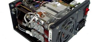
Once a customer at the service center was indignant that the switch for a screwdriver was expensive. And it’s expensive because it’s not easy.
The switch connects to the battery, the engine and contains a powerful MOSFET transistor that is mounted on the radiator behind the engine.
Reverse – purely mechanical switching of contacts (upper part). two contacts in the middle - turn on the motor, bypassing the electronics - this reduces the heating of the key and allows you to continue working if the electronics fail, albeit without a soft start. The diode below is protection against polarity reversal.
The button rod at the end is equipped with flexible contacts that move along the board, playing the role of a variable resistor. The board is made of ceramic and contains a PWM generator, the duty cycle of which depends on the force of pressing the button.
The output of this generator goes to a powerful MOSFET transistor connected in series with the motor, which is how they control the speed of the motor.
UPD 06/26/2020: It so happened that today I gutted a dead key from a Makita screwdriver. And it’s worth adding a little to the post, besides, so many years have passed.
The filling is similar. When released, the contact on the rod creates a short circuit for the motor - an electromagnetic brake. When pressed, this contact opens, then the contact deep in the case closes - it connects the negative battery to the circuit - the PWM generator is powered, which changes the duty cycle, controlled by sliding contacts on the board. In the photo I removed all the dirt, but there was a lot of dust and dirt inside. The oil seal on the rod did not save the dirt inside. I'm waiting for a small magnet to be placed on the rod, and the board with NE555 to be replaced with a specialized chip with a Hall sensor - this way we can get rid of sliding contacts.
The photo shows a PWM generator board based on NE555. The duty cycle setting resistor is on the reverse side. The board is made of fiberglass, not ceramic. The photo also shows a diode - it dampens the voltage surges that the motor inductance generates when the key is operating. If it weren’t for him, the MOSFET transistor would very quickly fail.
The photo shows electrical erosion of the contact, which provides engine braking by short-circuiting it.
When the rod moves to the end, the contact closest to us closes - it provides a bypass - closes the transistor, and so the power from the battery goes directly to the motor. It can be seen that the electrical erosion from soldering left nothing behind (the screwdriver worked in our workshop every day for about 5 years). Reversing is carried out by a group of contacts in the upper part - the motor connection is simply swapped.
The switch is completely disassembled. For those interested, I’ll say right away - the back-EMF suppression diode is 10A10 - 10 Ampere, 1000V. Can be replaced by anyone with a comparable current. Without it, the field-effect transistor will fail. The transistor itself is any n-channel MOSFET with a higher current and a lower channel resistance. (specifically here – IRF3205, 110A 55V, channel resistance 0.008 Ohm)
If you find an error, please select a piece of text and press Ctrl+Enter.
Repair of the electrical part of the tool - start button
Another malfunction of the Interskol Da-14.4 ER screwdriver may be a breakdown of the start button. It manifests itself in the absence of switching on of the tool, instability of operation, or spontaneous switching on. The cause may be metal dust formed, burnt contacts and a failed transistor.
To make sure that it is the button that is to blame for the failure of the screwdriver, you need to:
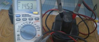
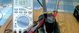
- Connect the battery and, after pressing the button, measure the voltage at its output. If it is missing, the button is faulty.
- Connect the engine and battery directly, bypassing the start button. For this purpose, remove the power source and remove the upper wire of the electric motor from the button. After this, two wires are connected at one end to the battery, and at the other to the motor housing and the wire going to the button. Turning on the screwdriver means that the trigger button is to blame.
Repair, as a rule, consists of replacing the old button with a new one. You can try to troubleshoot a used button. To do this, it is disassembled and, as necessary, the chips are removed, the contacts are cleaned, or the transistor is changed.
Post navigation
Screwdriver force regulator The force regulator is a clutch that limits the force when rotating the chuck. The torque control clutch ensures that rotation stops when the screw is screwed in, as it is accompanied by an increase in rotational resistance.
It is made in the form of a rotating plastic drum. If the speed controller does not work, it means the transistor has burned out and needs to be replaced.
For this purpose, you can gently lift the lid, noting the clear placement of the spare parts on the paper. When replacing, you need to ensure that the capacity and type of power element match. DC power is supplied from a battery, which is a set of elements housed in one housing. The diagram shows that when the contacts of the electromagnetic relay are closed, the positive voltage through the diode VD7 1N is supplied to the zener diode VD6 through the quenching resistor R6. The gearbox is driven by the rotor sun gear. Using a specialized chip Manufacturers of screwdrivers are trying to reduce prices for their products, often this is achieved by simplifying the charger circuit.
This means you should make sure to clean the device after each use - this is the only way to reduce the risk of failures during operation due to contamination of the tool. If the battery is good, then the next step is to check the power button.
If the elements of the printed circuit board are in good working order and do not raise suspicions, and the charging mode does not turn on, then you should check the SA1 JDD 2A thermal switch in the battery pack. Gearbox parts can be made of both plastic and metal.
By the way, the speed control button and the reverse control button are located in different places, so they will have to be inspected separately. The higher this indicator, the longer the screwdriver works.
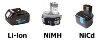
In the first case, they are capable of exploding, and in the second, they will no longer be able to restore their capacity. If such elements are found, they should be dismantled and replaced with new ones. Screwdriver battery repair
How to repair a device button? + (Video)
When everything is fine with the battery and charging proceeds without problems, but the tool refuses to activate, then check the serviceability of the device button.
To do this, you will have to disassemble the device and at its terminals coming from the button, you should measure the voltage with a multimeter, which comes at the input of the button. The operation must be carried out with an active battery. If there is a signal, then the battery must be removed and its contacts short-circuited using clamps. On the multimeter you need to switch to Ohm mode. The screwdriver button is pressed all the way and measures the output voltage. If the resistance reading on the device tends to zero, then the button is working properly. This means that the problem should be looked for in the brushes or other electric motor modules. If a signal break is detected, it is recommended to repair the button, thereby returning the screwdriver to working order. Quite often, problems with buttons are associated with poor contact at the terminals. You can simply clean the contacts with sandpaper and the problem will be solved. The main thing is to do everything carefully during the process of disassembling and assembling the device, without losing parts.
Schematic Electrical Diagram of a Screwdriver
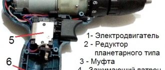
Now you have to use a soldering iron and unsolder the two elements from each other, as shown in the figure. Screwdriver design: 1 - speed controller with reverse, 2 - electric motor, 3 - gearbox.
Resistor Rx sets the highest current.
The graph shows how the temperature of the element temperature, the voltage at its terminals voltage and the relative pressure relative pressure change during charging. It can monitor battery parameters and, if necessary, reduce the current automatically. WE MAKE A SIMPLE BATTERY CHARGER with auto shutdown when fully charged
The electrical signal is supplied directly to the engine rotor through the commutator. Next, you need to carefully assemble the screwdriver button, install it in place and test it.
When the breakdown occurred, I was on business in Orenburg and therefore contacted the service center for repairs there.
Replaceable battery.
The rather miniature size of this tool assembly is achieved using microfilm technology.
We visually inspect the condition of the button for dirt and damage. repairing a screwdriver, replacing the power button with your own hands
Design and principle of operation of an electric screwdriver
Any push-button product of this kind has a protective mechanism. It can be used as an electric drill for drilling holes, but in short-term mode and without heavy loads. You will need two stabilizers: one is switched on according to the voltage stabilization circuit, and the second - on the current.
How to repair a screwdriver button if it does not work - detailed instructions To diagnose and repair a screwdriver, you will need the following tools: Phillips screwdriver; Screwdriver with a narrow flat slot.
They are engaged with the satellites on the pins of the carrier, between which the sun gear is placed. If you want to go the simpler route, then just buy a new button, which costs about r.
Also, 3 wires from the transistor responsible for adjusting the speed are connected to the button.
When rotating the chuck under load, there comes a time when more force is required to complete the job, for example, the last stage of tightening a screw, or when it is necessary to limit the force. The DC motor is made in the form of a cylinder, in which permanent magnets are located in a circle inside the housing. At the top there is a reverse button - a switch for the direction of rotation of the cartridge. Circuit with two transistors Another simple device can be made using available elements. In this case, repairs must be carried out using special tools. Repairing the Engine Brake The engine brake is a device that stops the rotation of the armature when the start button is released. connecting the drill button (part -1)