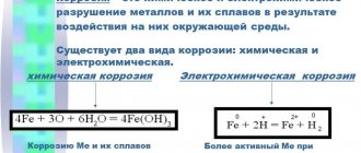
One of the requirements for hydraulic cylinders is the resistance of their parts to corrosion and wear. To ensure long-term performance of the cylinder and piston, high-strength structural materials and special protective coatings are used.
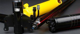
The most common control mechanisms for various equipment are hydraulic systems. The source of drive in them are hydraulic cylinders - piston, plunger, telescopic and others. By converting pressure energy into mechanical energy, they set in motion the necessary parts of machines.
Each type of hydraulic cylinders has its own design features. The most common are piston ones: simple, convenient and effective, they are used in a wide variety of applications. These devices got their name from the main operating component - a hydraulic piston.
Working principle of hydraulic piston
The piston is the main working element of a hydraulic cylinder. Under the influence of the working medium that enters its cavity, the piston moves back and forth. The speed of its movement depends on the intensity of fluid injection. As a result, the main purpose of the hydraulic cylinder is achieved - the transformation and transmission of energy.
The force of the piston is transmitted by a rod connected to it via a pin. The piston stroke is limited by the cylinder caps. Hard contact of this pair is prevented by special braking devices - dampers.
In the working chamber, the piston and rod form two cavities - piston and rod. The first is limited by the walls of the housing and the piston, the second - by the surfaces of the housing, piston and rod.
To prevent the working fluid from leaking out of the cylinder body, these cavities must be sealed, so the piston is equipped with special seals - cuffs made of oil-resistant rubber.
Hydraulic cylinder rod seal
The hydraulic cylinder
rod seal is also multi-component in structure.
In its standard form it contains only two elements. The first is dynamic, designed to provide low friction and enable operation at high speeds. This element is made of material compatible with many working environments. The second element - the O-ring - is static and ensures tightness. Based on the design of rod
sealing , the following types of products are used:
- Semi-compact rod seal
- Semi-compact rod seal with additional sealing lip
- Semi-compact rod seal with additional sealing lip and anti-extrusion ring
- Semi-compact rod seal with additional sealing lip, anti-extrusion ring and reinforcement element
- Rod seal with asymmetrical profile
- Rod seal with asymmetrical profile and additional sealing lip
- Rod seal with asymmetrical profile, with additional sealing lip and anti-extrusion ring
- One way rod seal
- Compact single-acting rod seal with anti-extrusion ring and elastic sealing element
- Spring reinforced rod seal
- Double-sided rod seal
Based on the operating conditions of the hydraulic cylinder and the type of design, the following substances can be used as a material for the manufacture of rod seals:
- Polyurethane PU
- Polytetrafluoroethylene PTFE
- Nitrile Butadiene Rubber NBR
- Thermoplastic polyester resin TPE
| Properties | Material for manufacturing wipers for hydraulic cylinders | |||
| P.U. | PTFE + bronze | PTFE + carbon | TPE | |
| Temperature | from -45° to +100°С | According to the scheme* | from -200° to +200°С | from -40° to +100°С |
| Speed | ≤ 0.5 m/s | ≤ 15 m/s | ≤ 15 m/s | ≤ 0.5 m/s |
| Pressure | ≤ 700 bar | ≤ 600 bar | ≤ 300 bar | ≤ 500 bar |
Diagram of temperature conditions for rubber components
| NBR rubber | FKM tires | VMQ rubber |
| -30°С +130°С | -30°С +200°С | -60°С +200°С |
Requirements for pistons and other parts of hydraulic cylinders
The piston, rod and liner body experience heavy loads during operation, so they are made of high-strength metals.
The pistons, which are in contact with the inner walls of the liner with their entire surface, are made of materials with high anti-friction properties - brass, fluoroplastic or bronze. Pistons with special guides and sealing rings are made of steel.
Piston hydraulic cylinders must be different:
- Smooth and uniform movement of the piston along the entire stroke length
- Low lateral loads on the rods - to avoid rapid wear of seals, pistons and the working surface of the cylinder
- Absence of external leaks of working fluid through fixed seals (on moving surfaces the presence of an oil film without drop formation is allowed)
- Minimum internal flow of liquid from one cylinder cavity to another (there is a certain technical standard)
- The presence of wipers that prevent dirt and dust from entering the cylinder cavities
- Resistance of the working surfaces of the cylinder-piston group to corrosion and wear (it is better if they have protective coatings)
The latter requirement is especially relevant for manufacturers of hydraulic equipment.
The problem of increased wear of cylinders and pistons is most effectively solved with the help of antifriction solid lubricant coatings. In Russia they are produced under the MODENGY brand.
Coatings facilitate sliding of contacting surfaces and prevent frictional wear. They simultaneously perform lubricating and protective functions.
MODENGY 1006 anti-friction solid lubricant coating is used to treat hydraulic pistons, rods and cylinder liners.
This coating contains two types of solid lubricants – molybdenum disulfide and polarized graphite – so it has a very high load-bearing capacity and wear resistance. MODENGY 1006 can be used even in extreme operating conditions of piston cylinders.
The material is applied to the rods, liner walls and piston surfaces in contact with them. The lubricant-protective film prevents the occurrence of scuffing, abrupt movement of mating elements and their corrosive wear.
It is recommended to apply another coating compatible with elastomers – MODENGY 1010 – under the rubber piston seals.
Before using coatings, metal surfaces must be prepared using MODENGY Metal Cleaner and MODENGY Special Cleaner-Activator. The first effectively removes any type of contaminants and degreases parts, the second ensures good adhesion of coatings.
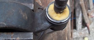
Wiper for sealing hydraulic cylinders
The wiper has quite a common name. This type of seal for hydraulic cylinder
literally removes all the dirt that gets on the stem from the outside.
In addition, it protects the system from dust or other foreign substances. A special edge allows it to achieve such characteristics. By the way, depending on the specific type
, wipers with different types of designs can be used for sealing For example, the following varieties are especially in demand:
- Wiper
- External wiper
- Wiper with outer edge
- Wiper with outer edge for heavy-duty use
- Wiper with additional projection
- Double acting wiper
- Double-acting wiper with additional projection
- Wiper in a metal frame
- Wiper with internal metal frame
Depending on the design and operating conditions, the material for the manufacture of such hydraulic seals
the following substances may become:
- Polyurethane PU
- Polytetrafluoroethylene PTFE
- Nitrile Butadiene Rubber NBR
- Thermoplastic polyester resin TPE
| Properties | Material for manufacturing wipers for hydraulic cylinders | |||
| P.U. | PTFE + bronze | NBR | TPE | |
| Temperature | from -45° to +100°С | According to the scheme* | from -40° to +100°С | from -45° to +140°С |
| Speed | ≤ 0.8 m/s | ≤ 15 m/s | ≤ 0.2 m/s | ≤ 0.4 m/s |
| Hardness | 93° Shore A | 70° Shore A | 90° Shore A | 55° Shore D |
Diagram of temperature conditions for rubber components
| NBR rubber | FKM tires | VMQ rubber |
| -30°С +130°С | -30°С +200°С | -60°С +200°С |
Types of piston hydraulic cylinders
Depending on the design features and operating principle (fluid movement), there are piston hydraulic cylinders:
- Single and double acting
- With one-way and two-way rod
- With movable rod and movable body
In single-acting hydraulic cylinders, the rod is extended by creating pressure of the working fluid in the piston cavity; it returns to its original position from the force of the spring.
In double-acting cylinders, the force on the rod is created both during forward and reverse movement of the piston - due to the pressure of the working fluid in the piston and rod cavities.
During the forward stroke of the piston, more force is transferred to the rod, and its speed of movement is less than during the reverse stroke - due to the difference in the areas to which the pressure force of the working fluid is applied.
If there is a need to create the same forces or the same speeds of movement of the output links, hydraulic cylinders with a double-sided rod are used. In them, one piston is connected to two rods. In modern technology, two types of such structures are used: with a fixed cylinder and with a fixed rod.
There are also single-acting and double-acting telescopic hydraulic cylinders. They consist of several cylinders, one of which is located in the cavity of the other. Despite their relatively small dimensions, telescopic structures have a large stroke and are therefore very effective.
Fittings with adjustable air flow
By changing the flow of air entering the pneumatic cylinder or the flow of air leaving it, we can regulate the speed of the cylinder. For this purpose, special fittings with flow control, also called throttles, are used. Let's consider the design of the throttle using the example of the MV 34 .. .. /B fitting (Figure 2). The flow regulator fitting has a constriction 3, to which the regulating element 2 is connected using a micrometric screw 1. Thus, by rotating the screw, the size of the flow section of the fitting and, consequently, the flow through it changes. Figure 2 also shows the designation of this fitting on pneumatic circuits.
Obviously, installing such fittings on both ports of the pneumatic cylinder (P1 and P2) will not allow you to independently control the speed of forward and reverse stroke of the cylinder rod, since the throttling of the air flow when passing through the fitting occurs in both directions. As a result, the speed of the rod movement will be limited by the lowest air flow.
Figure 2 – Fitting with flow adjustment series MV 34 .. .. /B
To independently control the speed of forward and reverse stroke of the pneumatic cylinder rod, flow regulator fittings with a check valve are used. Their designation on pneumatic circuits is shown in Figure 3a. When air flows from left to right, the check valve is closed and air does not pass through it (red arrow in Figure 3b). The air passes through a throttling device, with the help of which the flow rate is adjusted (blue arrow in Figure 3b). When air flows from right to left, the check valve opens and the main part of the air flow passes through it (red arrow in Figure 3c). Some air continues to flow through the throttling device (blue arrow), however, this has virtually no effect on the overall air flow.
Figure 3 – Operating principle of a throttle with a check valve
Thus, the use of throttles with a check valve provides regulation of flow when air moves in one direction and maximum flow when air moves in the opposite direction. Therefore, when installing flow regulator fittings with a check valve, the switching direction indicated on the pneumatic diagram should be observed. As a rule, on the fitting itself there is a conventional graphic designation, which makes it clear in which direction the air flow is regulated, and in which the full flow is ensured. For example, Figure 4 shows the location of such a designation for fittings with flow control MV 21 and MV 34.
Figure 4 – Flow regulator fittings with check valve
Materials
The guide rings are made of anti-friction wear and oil-resistant materials. Let's look at the most popular:
O-ring materials
- Fluoroplastic - turquoise color, resistance to mechanical, frictional and thermal loads, resistance to aggressive substances, low electrochemical corrosion, low water absorption coefficient and lack of magnetic properties.
- Cotton fabric – light brown color, high mechanical strength, easy to machine, resistant to aggressive environments.
- Aramid fabric - gray-black color, used for piston alignment, resistant to aggressive environments, increased impact strength, wear resistance and heat resistance.
Support and guide rings for hydraulic cylinder
Support-guide rings are used as a substitute for standard bronze guides. These products are capable of ensuring linear movement of the rod, preventing contact between the metal of the rod and the metal on the hydraulic cylinder cover (rod support rings) or contact between the metal of the piston and the liner (piston support rings) when exposed to radial loads perpendicular to the direction of their movement. By type of design, support and guide rings
have the following purpose:
- Rod guide ring
- L-shaped rod guide ring
- T-shaped rod guide ring
- Piston guide ring
- Rod and piston support ring
- Support-guide ring of plunger hydraulic cylinder
Based on the operating conditions of the hydraulic cylinder and the type of its design, the following materials can be used for the manufacture of
support and
guide rings :
- Fluoroplastic
- Polyamide
- Reinforced fabric
| Fluoroplastic | Aramid fabric | Polyamide | |
| Temperature | From -40°С to +200°С | From -40°С to +120°С | From -40°С to +100°С |
| Speed | ≤ 5 m/s | ≤ 1 m/s | ≤ 1 m/s |
| Load | ≤ 15 N/mm2 at 20° | ≤ 50 N/mm2 at 120° | ≤ 30 N/mm2 at 100° |