- Piston and other hydraulic cylinder elements
- Types of piston hydraulic cylinders
- Main parameters of piston hydraulic cylinders
Hydraulic cylinders are widely used in hydraulic systems of vehicles and industrial equipment. These devices act as actuators or drive sources.
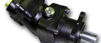
Piston hydraulic cylinders are the simplest, most convenient and multifunctional type of these devices. Their main functional element is a hydraulic piston. Under the influence of the working fluid pumped into the cylinder cavity, it performs a reciprocating motion at a certain speed.
As a result of the movement of the piston, hydraulic energy is converted into mechanical energy - thereby performing the main function of the hydraulic cylinder.
Types of piston hydraulic cylinders
Depending on the operating principle and design features, the following piston hydraulic cylinders are used:
- With a movable body or rod;
- One-sided, two-sided;
- With one-way, two-way rod.
In one-way hydraulics, the rod extends as a result of the pressure of the process fluid in the piston. It is moved to its original position under spring force.
In double-acting hydraulic cylinders, pressure is built up both during the forward and return strokes of the piston due to the process fluid in the rod and piston.
What is a rod piston
Based on the name of the part, answering the question of what a rod piston is is quite simple. It transfers energy that allows the element to perform translational movements. Without this, car steering and maneuvering would be impossible.
It is worth noting that the operation of the steering rack and the control of the car as a whole depends on the condition of the piston and rod. Therefore, special attention should be paid to the condition of these parts. Also, you will most likely be interested in the topic of why a toothed rack is needed and what functions it performs.
If problems occur in the steering system, experienced specialists first of all pay attention to the condition of the rod system. Knocking, “biting” of the steering wheel or leakage - all this can be corrected by replacing parts. For example, a new piston, bushing and oil seals will significantly improve the condition of the unit and help save on repairing the entire rack.
How are hydraulic cylinders made?
Like other mechanisms, the hydraulic cylinder is subject to wear, which is associated with the overload to which all elements are subjected. As practice shows, it is more expedient to make a hydraulic cylinder yourself, or order it from a workshop, than to buy a new branded analogue. Savings can reach several thousand rubles. As a rule, a new hydraulic cylinder is produced to replace equipment that unexpectedly fails, or as a reserve, as a replacement for a hydraulic cylinder if signs of wear begin to appear, it should soon be written off.
The technology for creating a new custom hydraulic cylinder assumes that it is a one-off product. When creating it, the original is used, from which measurements are taken. The new unit must correspond in all technical characteristics to the failed one. To do this, before starting work, drawings and technical specifications are drawn up, and the old product is photographed. If possible, original factory documentation is obtained, which allows you to create an absolutely identical hydraulic cylinder.
Among the main points that should be specified in the technical specifications:
- Diameter of the stroke piston;
- Travel speed;
- Rod diameter;
- Operating pressure.
The technical documentation on the basis of which the new hydraulic system will be developed must be both concise and informative. The absence of errors, a responsible approach to the drawings is a guarantee that the customer will be given a piston that, in terms of its dimensions and, most importantly, technical characteristics, will fully correspond to the source.
Stages of creation
The production of a hydraulic cylinder requires modern equipment, high-quality materials, and knowledge of advanced technologies. Only by combining these elements can you create an original design that completely replicates the original features of the original mechanism.
The design of a hydraulic cylinder combines a sleeve, a rod, and seals. During the production process, these elements are machined and then assembled into a single system.
The manufacturing technology of a hydraulic piston consists of several stages:
- Pipes and rods are cut into blanks on a band cutting machine;
- The sleeve is chamfered from sections for welding work;
- The sleeve is welded into a single structure with rear covers and bonks;
- The rod is processed on a lathe and adjusted to the dimensions specified in the technical specifications;
- The elements are being assembled.
Before final assembly, all parts are washed in a washing machine. The seals are attached to certain areas of the hydraulic cylinder body using an installation tool. The heat resistance and tightness of the chamber where the cylinder runs is ensured by glue and o-rings.
Before transferring the finished order to the client, the hydraulics are tested on a test bench. The performance of the piston system is checked, both at idle and under various loads. The quality of the product is confirmed by the appropriate markings on the case, warranty card, certificate, product passport. The finished cylinder is packed in shipping packaging.
To ensure that the cylinder operates reliably throughout its entire service life, it is made from European components from trusted brands. The minimum period of the factory warranty is 12 months. The duration of the warranty depends on the type of cylinder, the materials from which it is made, and design features.
You can order the production of a hydraulic piston by calling the phone number and address indicated in the header of the site.
Repair of piston rod stuffing box
Typically, repairs to the piston stuffing box are performed using known methods when dismantling the pistons. During such repairs, the piston is located on the caliper above one of the cutouts in the upper platform. Therefore, work with the stuffing box is performed from below the platform as follows:
- Place two lugs on the stuffing box flange and engage the two claws. Raise the piston rod slightly and secure the work table around the rod at a convenient height for working. Place the stuffing box on a workbench and remove the clamps and lugs.
- Remove the O-rings from the stuffing box. If the O-rings are normal and will be used again, slide them up the stem and secure them in this position, for example with tape. Unscrew the nuts of the stuffing box assembly bolts.
- Remove six bolts, and move one half of the stuffing box. Place two eyelets on the stuffing box half and remove it from the table.
- Using a feeler gauge, measure the vertical gap of the rings. See “Piston Rod Packing Box.” Checking the stuffing box."
- Remove the other half of the stuffing box and slide all the O-rings and scraper rings down toward the workbench.
- Measure the gap between the ring segments to determine the need for replacement. “Piston rod stuffing box. Checking the stuffing box." Dismantle and stack the rings in the same order as they were mounted in the box. Clean all ring segments thoroughly. Check and evaluate the quality of all O-ring surfaces. If their surfaces are scratched or marked, replace the rings.
- Check the length of the springs, see “Piston rod stuffing box. Checking the stuffing box."
- Check the surface of the piston rod. If there are small scratches along the length, carefully grind the surface of the piston rod with a fine-grained carborundum stone. In case of large scratches, machine processing in workshops may be necessary.
- Clean the stuffing box housing halves.
- Lubricate the piston rod (in the area where the ring sets will be located in the stuffing box) with molybdenum disulfide MoS2. Assemble all packing box ring sets around the piston rod on a workbench as follows:
Repeat this procedure for the remaining scraper rings. On top of the scraper rings, assemble two sets of o-rings (each consisting of a 4-link ring and an 8-link ring). Mount the 8-link O-ring so that the two guide pins are facing up; place the spring around the segments and lock the ends of the spring together. Mount the 4-bar O-ring over the 8-bar O-ring. Push the two rings together until the guide pins on the lower o-ring engage with the two holes on the upper o-ring. Finally, assemble the topmost spring kit, consisting of a 4-bar scraper ring and an 8-bar O-ring.
Hydraulic piston device
Hydraulics are structurally of two, characteristically different, types:
- The sliding inner plane of the liner, which has direct contact with the piston. This design requires the manufacture of a liner from antifriction materials;
- The piston, where sealing and guide rings slide along the liner, for which special grooves are machined. This is a more popular option that is cheaper to produce. The main material for the mechanism is steel.
To prevent the cylinders from leaking, cuffs and rings are used. If pressure is pumped from both the piston chamber and the rod side, install 2 in different directions. If pressure is applied only on one side, one cuff is sufficient.
The piston serves to sense steam pressure and hermetically separate the two cavities of the cylinder.It consists of two main parts: the piston body and the piston rings. In fig. Figure 43 shows the most commonly used types of steam engine pistons.
The material for hollow pistons is usually cast iron SCh 21-40, and in critical cases SCh 28-48 or SCh 32-52. Disc pistons are forged from 50 steel.
To prevent the piston from jamming when heated, its diameter is taken to be 1/600 smaller than the diameter of the cylinder. The length of the piston is determined by the specific pressure on the cylinder walls, which should not exceed 1 - kg/cm2, the load is considered to be the weight of the piston and half of the rod, and the supporting surface is the product of the length of the arc, equal to 0.75 of the cylinder diameter, and the length of the piston without the total height of the piston ring grooves.
The tight fit of the piston to the cylinder walls is ensured by piston rings located in grooves on the outer surface of the piston. They are made from cast iron SCh 21-40 or SCh 24-44. The number of rings is 2-4. Casting defects in blanks for rings are not allowed.
The elasticity of the ring is achieved by cutting out the part of the ring that forms the lock. A ring lock with an oblique or straight cut (Fig. 44) is the simplest and most reliable. The locks of the rings placed on the piston must be mutually offset, and spontaneous displacement of the rings must be prevented using locking pins or screws.
The rod is made of steel 50. One of the typical methods of attaching the rod to the piston is shown in Fig. 43 and is clear from the figure.
In medium and large machines, in order to reduce the pressure from the weight of the piston on the lower wall of the cylinder and prevent bending of the rod, the latter is passed through both covers. In this case, the rear part of the rod is called the counter rod.
In fig. Figure 45 shows two typical connecting rod designs. The main elements of the connecting rod are the crank head 1, the connecting rod rod 2 and the crosshead head 3. The material for the connecting rods is usually 40 or 50 steel.
The device that pivotally connects the piston rod to the connecting rod is called a slider or crosshead. In the absence of a crosshead (as is the case with most internal combustion engines), it would be necessary for the piston itself to act as a slider directing the movement; then it should have been given the shape of an elongated glass, the guides of which would have been the walls of the cylinder; under these conditions, a direct hinge connection between the piston and the connecting rod would arise; but this is only possible if the cylinder does not have a cover on the shaft side.
The main shaft can be crank or crankshaft.
The crank shaft is shown in Fig. 46. It consists of a body 4, a crank 2 and a pin 1. The shaft rests on bearings 3 and 6; bearing 6 is remote and not connected to the machine frame. A flywheel is mounted on neck 5. The crank is secured to the shaft with a key.
In fig. Figure 47 shows the crankshaft of the compound steam engine of the SK locomotive. Here the shaft also rests on two bearings 4. The spool eccentrics c are mounted on the shaft. V. d. 3 and c. And. 12, flat regulator 2 and flywheels 1, sitting on both sides of the bearings. The shaft material is usually 40 or 50 steel.
Flywheel , in addition to its main purpose - to maintain a more or less constant angular velocity, often also serves as a pulley. In most cases, the flywheel is split, and both halves can be bolted together on the hub and rim. Bolts are usually made from 40 or 50 steel.
The bolts holding both halves of the rim are calculated based on force
Q = 0.104u2f kg,
where u is the peripheral speed of the rim in m/sec\
f is the cross-sectional area of the flywheel rim in cm2. Sometimes, when the flywheel has a diameter of no more than 2 m and is mounted on the free end of the shaft, it is made in one piece. The flywheel is most often cast from cast iron grade SCh 15-32.
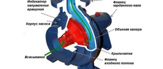
Principle of operation
The piston is the main element of the hydraulic system. It moves back and forth inside the chamber and is driven by the working medium. The speed of movement depends on the intensity of the pressure of the process fluid. As a result of the process, it produces a transformation, a transfer of force. The energy of the piston is transmitted by a rod, which is attached to it through a pin. The stroke of the piston is limited by the size of the chamber. To soften contact, dampers are installed on the cylinder chamber covers.
The tightness of the system is ensured by seals - cuffs made of oil-resistant rubber.
Piston and other hydraulic cylinder elements
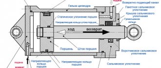
As noted above, the piston is the main link of the hydraulic cylinder. Under the influence of the pressure of the working fluid coming from the holes in the cylinder covers, it moves smoothly and evenly. The impacts of the piston on the covers are softened by special braking devices - dampers.
By means of a pin, the piston is connected to a rod, to which it transmits its force. The piston and rod form corresponding cavities in the chamber: a piston cavity, limited by the surfaces of the body and piston, and a rod cavity, limited by the surfaces of the body, piston and rod.
Internal fluid leakage from one cylinder cavity to another should be minimal. In order to seal the cavities, special seals made of oil-resistant rubber are installed on the piston. To prevent the entry of dirt and dust, wipers are used.
All the main elements of the hydraulic cylinder - the liner body, the piston and the rod - are made of metal that can withstand significant loads.
Pistons, equipped with special guides and sealing rings, are usually made of steel. Devices that do not have rings and are in contact with the inner walls of the sleeve with their entire surface are made from materials with improved anti-friction properties - brass, fluoroplastic or bronze.
The working surfaces of the cylinder parts must be resistant to corrosion and wear. That is why many manufacturers of hydraulic equipment treat parts with special anti-friction coatings (AFC).
In Russia, such materials are produced using a unique solid lubricant technology; as a result, their properties are superior to factory coatings.
AFPs facilitate the sliding of rubbing surfaces and prevent frictional wear of parts, thereby combining the functions of a lubricant and a protective coating.
In order to extend the service life of hydraulic pistons, rods and hydraulic cylinder liners, MODENGY 1006 anti-friction coating with molybdenum disulfide and polarized graphite is used. It has a very high load-bearing capacity and wear resistance, so it can withstand any operating conditions of piston cylinders.
AFP prevents corrosive wear of metal elements, the occurrence of scuffing and subsequent stick-slip motion. The coating is resistant to the pumped media and has the properties of emergency lubrication.
It is recommended to treat areas in contact with rubber seals with another coating compatible with polymers and elastomers - MODENGY 1010.
In order for the AFP to lay down evenly and efficiently, before applying it, metal surfaces should be thoroughly cleaned and degreased - for example, using MODENGY Metal Cleaner. For final preparation of parts and improvement of coating adhesion, you can use the MODENGY Special Cleaner-Activator.
How the piston rod is sealed
Let's look at how the piston rod is sealed and what is needed for this. This process is carried out using special rubber rings, which are installed and secured in the recesses of the housing. When tightened, they fit tightly to the surface, securely fixing the connection.
To remove dirt and carbon deposits from automotive connections, a decarbonization procedure is carried out. Without it, the mobility of the piston rod parts will be significantly reduced. Therefore, car owners have a question: what is the best way to decarbonize piston rings and how to do it correctly. Carrying out this simple procedure regularly will prevent the occurrence of malfunctions in the control unit.
Piston rod diameter
How to choose the correct piston rod diameter for the steering rack of your car? The easiest way to look at the technical specifications of the part is in the instruction manual. Also, when ordering a part, you should check the VIN code and use it to select the appropriate parts.
If you decide to hand over the repair of the rod to professionals, they themselves will select the part of the required diameter. It is worth noting that repairing the steering rack of a Kia or other car requires knowledge and experience. That is why it should be entrusted to qualified craftsmen who have all the necessary skills.
It should be remembered that when selecting a part, several characteristics are taken into account: external and internal diameters, and thickness of the part. If one of these indicators is more or less than required, the piston rod may “rise” incorrectly and lead to failure. To avoid this, be careful when selecting the part. If the piston does not fit even by a millimeter, it is best to replace it with a suitable one.
LAST NEWS
The line of EFELE brand cleaners has been replenished with new water-based formulations
With the use of MODENGY coatings, the amount of defects in the production of spoilers for trucks is reduced to a minimum
Source of the article: https://borfi.ru/press/409.html
Typical hydraulic cylinder designs
Despite the huge variety of designs of hydraulic cylinders, there are typical solutions used in the design of hydraulic cylinders; we will consider some of them.
Hydraulic cylinder on studs
The front and rear covers of hydraulic cylinders of this design are connected by pins (anchors), the sleeve is sandwiched between the cylinder covers. The piston is sealed by two cuffs.
Round hydraulic cylinder
In the presented design, the covers are attached to round flanges secured by welding or threading to the sleeve. The type of piston seal shown in the illustration provides sealing in both directions.
Welded hydraulic cylinder
The covers are welded to the sleeve, the structure is non-separable and cannot be repaired. The cylinder has compact piston seals.