Drilling machines can be classified as equipment with universal capabilities. At the same time with the ability to drill holes of various diameters, cleanliness and accuracy, with their help it is possible to perform numerous operations in accordance with the technological process of surface treatment. The use of this category of equipment is optimal if the technology provides for the following actions:
- drill, bore holes of various diameters;
- countersink the drilled holes to the appropriate parameters, countersink the necessary recesses to accommodate the protrusions of the fasteners;
- expand the surface of the holes within specified limits;
- roll out holes using ball and roller mandrels to a given level of roughness;
- perform internal thread cutting;
- trim (chase) the ends of parts in order to align them.
There are also other possibilities for using equipment in this category.
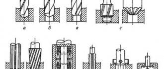
Rice. 1. Work performed on drilling machines
a – drilling; b – drilling; c – countersinking; g – countersinking; d – deployment; e – rolling; g – cutting internal threads; h – cutting (countering) the ends
Tools
To solve these problems, a series of special tools have been developed with different characteristics and design solutions for cutting surfaces, edges, for which special cutting angles, helix length, configuration of recesses for chip removal, etc. are provided. Depending on the cutting operations performed and the technical qualities of the processed materials, tools are used with the corresponding parameters:
- drills of various diameters;
- sweeps;
- countersinks;
- countersinks;
- taps, etc.
In order to obtain the required purity and precision of processing, there are special devices used for:
- fastening the tool in the machine spindle;
- placement and fastening of the workpiece;
- holding fasteners on the machine table, etc.
Auxiliary Tools
The mounting of the cutting tool listed above in the machine spindle is carried out using auxiliary tools:
- adapter drill bushings;
- drill chucks;
- mandrels, etc.
In cases where the size of the cone in the machine spindle does not coincide with the cone of the tool shank, the tool is fastened using adapter conical bushings. If the production does not have the required bushing number, it is possible to use several bushings, however, the accuracy of the part may suffer. Most often, adapter bushings with a Morse taper are used (No. 0...6).
Fastening cutting tools with a cylindrical shank on drilling machines is also done using two- and three-jaw drill chucks. In a three-jaw chuck, cage 3 with nut 2 is rotated by key 4. When the nut rotates, the cams 1 connected by it move downward, clamping the shank of the cutting tool. By rotating the key in the opposite direction, the cams unclench, releasing the tool.
Rice. 2. Drill chuck for holding straight shank drills:
A – general view of the chuck with a key for clamping the workpiece; b – cartridge device; 1 – cams; 2 – nut; 3 – clip; 4 - key
The two-jaw chuck contains jaws that move along T-shaped slots in accordance with the rotation of the key and clamp the tool shank. Small-diameter drills are easily secured in collet chucks, and to save time, it is convenient to use quick-release chucks for tools with tapered shanks, into which tools can be installed and removed without stopping the machine. Drills with a diameter of up to 10 mm with cylindrical shanks are mounted in a chuck with a Morse taper using an adapter conical split sleeve.
In order to ensure exact alignment of the centers of the holes when performing several successive operations, it is most advisable to use self-aligning chucks.
Rice. 3. Quick-change drill chuck (a) and conical bushing for fastening drills with cylindrical shanks (b):
1 – cartridge body; 2 – replaceable bushing; 3 – balls; 4 – coupling; 5 – ring; 6 - mandrel
Thread cutting is an operation that requires maximum precision. In order to ensure accurate parameters during its execution, the taps are mounted in safety chucks, which also ensure the safety of the tool, protecting it from breakage. During the threading process, a tight connection is ensured between the driving coupling half 5 and the driven coupling halves 2.4. Upon completion of the operation, the coupling half 5 slips, the tap is removed from the hole by reverse rotation of the spindle. In cases where the machine is not equipped with a reverse system, they resort to the use of reversible chucks, which ensure the reverse movement of the tap from the threaded hole.
Rice. 4. Safety chuck for tapping blind and through holes:
1 – ring for fastening the tap; 2, 4 – driven coupling halves; 3 – clutch cams; 5 – driving cam coupling half; 6 – spring; 7 – mandrel; 8 – adjusting nut
With the help of swinging mandrels used to fasten reamers, it is possible to maintain centering accuracy when machining holes. The issue of removing the main and auxiliary tools from the spindle socket is easily resolved - specially shaped wedges or eccentric keys are used for this.
| Rice. 5. Wedges for removing tools from the machine spindle: a – flat wedge; b – radius wedge | Rice. 6. Eccentric wrench for removing the cutting tool from the machine spindle |
Drill Guide Features
The drill stand has several important characteristics:
- Vertical stroke (how far the tool can be moved vertically).
- The diameter of the fixing flange (determines what size tool can be clamped).
- Material.
- Size and weight of the device.
Drilling stands can be mobile or stationary. The stationary guides are very reminiscent of a small drill press, they look like a tripod for a drill. Mobile guides are attachments for drilling tools. Their main advantage is their very high mobility.
An important property of the rack is the method of fastening. The most reliable option is a magnetic mount. There is also a simpler option - this is a vacuum mount.
Mobile devices fit comfortably in your hands and absorb vibration when drilling. Most people choose mobile guides. All thanks to their excellent characteristics. They are very reliable, compact and have a low price.
Devices for fastening workpieces
An important point in metal cutting is the installation on the machine and fastening of the parts to be processed. Parts are installed on special devices, including:
- on a vice - machine, eccentric, screw, pneumatic;
- prism;
- squares;
- stops;
- conductors.
Depending on the speed and strength of fastening, manual (in small production) or pneumatic devices are selected, ensuring high speed of installation and fastening.
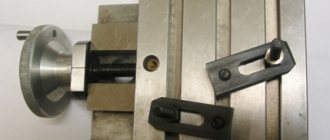
The most suitable for quick installation of workpieces are vices operating on the basis of a lever-cam mechanism. Clamping of the part between the movable and fixed jaws occurs due to the movement of the movable jaw, which is movably connected to a double cam and an eccentric roller. One movement of the handle in the horizontal direction achieves a rigid clamping of the part in the desired position.
Rice. 7. High-speed machine vice with lever-cam clamp: 1 – body; 2 – rotating part; 3 – fixed sponge; 4 – screw; 5 – sponge; 6 – handle; 7 – eccentric shaft; 8 – double cam; 9 - base
Conductors
An important device for precise centering of the axes of the tool and the hole being machined are jigs. The jig is installed above the part with a small gap to remove chips and is mounted on the machine table. In the body of the conductor there are holes, inside of which there are conductor bushings made of especially hard grades of steel that have undergone heat treatment (20X, U10A).
Rice. 8. Conductor bushings: a - permanent; b – quick-change
Permanent and quick-change bushings are used to ensure precise guidance of the cutting part of the tool in accordance with the specified parameters. There are special requirements for the distance between the workpiece and the jig, depending on the material being processed and the quality of the chips during processing. For cast iron parts, a gap of 0.3-0.5 from the diameter of the conductor bushing is assumed. The gap increases and can reach the diameter of the bushing if steel, copper and aluminum alloys, etc. are used as the material being processed.
The design of the conductor includes a body and a plate, which, depending on the purpose, can be:
- Removable (subject to replacement when changing workpiece parameters).
- Suspended, convenient when working with multi-spindle drilling heads. The hanging plate is placed on two rolling pin guides. The drilling head installed in the spindle of the machine is equipped with bushings that align with the upper ends of the rolling pins.
- Lifting ones, which move on rolling pins pressed into the conductor body using a pneumatic drive.
- Rotating (for ease of removal and installation of each subsequent part).
- Permanent (fixed in the conductor body using fasteners or welding).
Conductors significantly facilitate the work of workers, eliminating the preparatory work on marking and precise reinstallation of parts when performing operations on the equipment of the drilling group, ensuring the accuracy of the direction of the cutting tool. In accordance with the processing technology and production conditions, conductors of various designs are used, called:
- rotary.
- sliding.
- overturned.
- invoices.
The most common devices are overhead jigs, which are applied to the workpiece and fixed with metal fingers in a position that ensures the operation is performed in accordance with the technological map. The part is preliminarily fixed on the work table using an appropriate device that ensures the centering of the guide bushings of the jig with the axes of the holes drilled in the part. Conductors of this type can be mounted on a desktop (fixed), or installed on fixing fingers (unfixed).
Rice. 9. Unfastened overhead jig: 1 and 2 – fixing fingers; 3 – guide bushings; 4 – conductor plate; 5 – base surface of the device; 6 – holes
Rotary equipment
For the convenience of processing parts in accordance with the selected technology, appropriate rotary and movable equipment is used, which significantly facilitates the work without requiring reinstallation of parts for drilling or performing other operations for high-quality processing of holes. In such cases, it is assumed that special racks and tables will be used, including normalized, rotary and mobile ones. These are quite complex structures, which contain removable, including rotary, conductors. In this case, the conductors act as elements that guide the cutting tool during the corresponding operations. The main devices designed to move fixed workpieces on a machine in accordance with the requirements of the technological process are:
- rotary racks with a horizontal axis of rotation of the faceplate in which the workpieces are secured;
- rotary tables rotating around a vertical axis and located in a horizontal position.
Universal devices
Universal prefabricated devices (USP) are used when performing various metal cutting operations. USP are special devices that hold the workpiece in the position necessary to ensure precise machining of parts. Versatility lies in the ability to quickly install the workpiece, and, if necessary, to quickly retool the device.
An important device that provides the ability to perform several simultaneous or sequential operations on machine tools is multi-spindle drilling heads. These devices are used in large industries for drilling holes and their subsequent processing, which leads to a real acceleration of the process of manufacturing parts of complex configurations.
Turret drilling heads can contain a different number of spindles equipped with a cutting tool in accordance with a technological program that provides for sequential execution of operations. In this case, it is possible to set your own rotation speed for each spindle separately. In addition, the tool is fed at a certain speed in the forward and reverse directions. This head design makes it possible to operate and perform programmed operations without readjustment. Turret heads are provided with replaceable spindles with various design capabilities used in the technological process of cutting complex parts with the required accuracy and surface finish.
Rice. 10. Six-spindle turret: 1 – lock; 2 – lock lever; 3 – driving coupling half; 4 – clutch lever; 5 – main body; 6 – rod; 7, 8 – thrust screws; 9 – rack; 10 – gear; 11 – bevel gear; 12 – ratchet mechanism; 13 – serratus vein; 14 – rotary body; 15 – head spindle
The rotation and feeding of tools installed in each spindle is carried out in a programmed automatic mode, for this there is no need to stop the equipment for subsequent readjustment. Servicing machines with such complex devices requires highly qualified machine operators and technologists who develop the cutting process. The sequence of operations is carried out in accordance with the program: rotation of the head and feeding of the tool in the vertical direction is carried out in the required mode and compliance with the speed of rotation and feeding of the tools. After performing a certain operation, the head rises and rotates for the next operation.
Application area
The drilling tool is used to produce various through and blind holes.
By setting a certain drill rotation speed and feed, it is possible to ensure that the required amount of metal is removed from the surface.
The scope of application of this type of machine is very extensive:
- In industry . Most models that are on sale are intended for industrial use, for example, in the engineering field. Industrial machines are characterized by high efficiency. The drilling bench used in industry has large dimensions and weight. Purpose of industrial equipment: setting up production in engineering, machine tool and other industries.
- At home . Every year there are more and more machines used in everyday life on sale. Such equipment is characterized by less functionality and efficiency, but at the same time it is smaller and more economical. As a rule, the household model is represented by a simplified design of an industrial version, which can be installed on a workbench or other elevation.
There is also a turning and drilling machine, which can be used for a wide variety of operations. However, they are inferior to vertical drilling machines in terms of versatility.
Types of industrial models
Many devices are represented by universal equipment that can be used for drilling not only in metal, but also in other materials. The following types of drilling machines are distinguished:
- Tabletop type. This group is characterized by compact size and low weight. Area of application: obtaining small diameters.
- Column machines are installed in the case of establishing single and small-scale production. When using them, it is possible to obtain holes with a diameter from 18 to 75 mm.
- Radial drilling machines are used for processing massive parts. In this case, the resulting holes can be located strictly along a circular arc with a given pitch. A distinctive feature of the layout is the rather large overhang of the spindle assembly beyond the structure.
- Jig-drilling structures are widely used when it is necessary to obtain a workpiece with the exact location of holes relative to each other.
- Centering models are designed for processing end holes. This design is characterized by a large distance between the work table and the spindle head.
- Horizontal drilling machines are designed for processing shafts and axles, as well as rods and other similar products. The layout features make it possible to obtain holes of considerable depth.
- Multi-spindle designs can be used to produce multiple holes simultaneously. Moreover, they can be located in different planes.
- Combined devices have a layout that allows several different operations to be carried out at once: drilling, milling, chiselling, and so on.
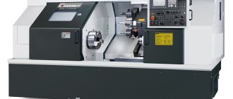
Recently, designs that operate under CNC control have become widespread. They are used to produce the most complex high-precision products.
Design and capabilities of industrial drilling remains
The design of industrial drilling machines is more complex than that of household units, and the capabilities of such devices are very great. Such machines can process workpieces made of any metal and other materials of considerable thickness.
The electrical circuit of industrial drilling machines is reliable. Most of these units have the ability to automatically change the direction of rotation of the drill. Almost all models of industrial machines are equipped with a liquid supply system for cooling.
Photo No. 4: device of an industrial drilling machine
CNC: classification and explanations
Today CNC is used everywhere in machine tools, with the only caveat that it is strictly for technological needs: if it is possible to make a part, and there are no requirements for super-precision of its execution, you can simply invite an experienced craftsman to work on it, who will carry it out on a familiar manual machine.
Although for home work (for jewelers, wood and metal artists) there is a miniature tabletop machine, it is no less professional and reliable.
Video:
So the price and the question of appropriateness, although banal, are vital. Technologically, the CNC system can be divided into 2 groups:
- Positional: the drill and the workpiece move intermittently - point by point. In this case, the positions are either far away (say, when boring and drilling), or close to each other (as when turning and milling);
- Continuous movement: contour work in one movement.
The CNC positional system is the simplest type of control, but is used mainly in drilling and jig boring machines, where shaped movement is not required - only in a straight line.
The rectangular CNC system moves the drill one at a time along a specific coordinate axis, while the speed of movement is set by the program itself.
This system is also used to a limited extent (comparatively) on workpieces that can be placed parallel to the coordinate axes (turning, milling).
CNC shaping
This type of CNC needs to be discussed separately. This is a more advanced option for positioning and work in general, since the tool moves along two or more coordinates, which allows processing workpieces of any shape.
The interpolator simultaneously produces coordinates in three-dimensional space in the form of a certain number of feed drives. Today, more and more machines are being produced with CNC shaping.
Video:
Yes, they are expensive, but such professional equipment quickly pays for itself, as it allows you to produce complex parts that are not cheap.
But even such an innovative machine can offer a choice of options: 2D and 3D shaping.
2D shaping is controlled along two coordinate axes, which means you can move the drill along an arc and a straight line. A particular version of this type is 2½D shaping.
IMPORTANT TO KNOW: Operation of CNC milling machines for metal
The drill already moves along 3 coordinate axes, but the difference is that only 2 axes are controlled, and the third is used for installation, approach and retraction of the tool.
After executing a command to move in a certain plane, the system can switch to movement in another.
The current processing plane, coupled with the simultaneous control of different axes, allows the drill to operate in the XY, XZ, YZ planes.
This CNC system is used in simple machines that are equipped with a stepper feed drive.
What is noteworthy is that complex contours and surfaces can be processed on the machine, but a volumetric part is processed layer by layer in a specific vertical or horizontal plane, and not continuously.
3D shaping is the crown of machine tool engineering, which produces high-precision parts with a smooth surface.
Video:
The machine tool moves along 3 axes at once, which means you can process any spatial contour continuously. For the most part, the milling method is used rather than drilling.
However, if the machine is universal, and even with 3D, then it will perform any part, not to mention ordinary drilling. The price of such a unit sometimes reaches several thousand euros.
DIY drilling machine
In order not to waste time searching for a suitable option and money for purchase, you can make a suitable device for your needs yourself. A homemade drilling machine can be created from an ordinary drill. The design includes the following elements:
- electric drill;
- base;
- stand;
- drill mount;
- feed mechanism.
A home drilling machine is assembled as follows:
- Creating the foundation. The wooden block is secured with self-tapping screws on any base. You can take a deck, the main thing is that its weight is greater than the drill.
- Assembly of the mechanism. The furniture guide is screwed to the block. Using a cutter, drill a hole in a wooden board for the base of the drill. The corner is fixed on the board. The resulting structure is connected to a guide, which is then inserted into the base.
- They make a handle for moving the platform. A corner is attached to the deck and a wooden plank is attached to it. The steel plate is connected at one end to the platform and the other end to the handle.
- Secure the drill to the platform using a clamp.
- For additional stability of the structure, the deck is fixed using corners on a square tabletop.
- The spring is secured at one end to the stand and the other to the platform.
- Create a stand for the machine. A small board is screwed to the tabletop.
