A flange connection is quite often used instead of conventional welding, and even more so for a fitting.
Flange connection
The flange guarantees an equally strong and tight connection, but is also detachable, which allows you to dismantle part of the pipeline at any time for repairs, for example, or connecting additional sectors.
How to weld a flange to a pipe evenly
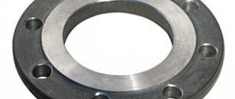
Flanges are steel disks (rings) of various configurations; they are designed for quick-release connections on pipelines.
They are attached by welding to pipe sections. They are necessary for installing shut-off valves, metering devices, and when installing new bends. They are put on the edge of the pipe. The most effective way to attach a flange to a pipe is welding. The rings must be fixed without distortions, strictly along the cross-section of the pipe. Welding of flanges is carried out in several ways; each technology has its own nuances that must be taken into account to obtain a high-quality sealed seam that does not impede the flow of the transported liquid.
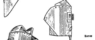
Flange conductors
For ease of installation and welding of flange connections, a special device called a jig is used. The conductor allows you to assemble connections in strict accordance with the technical conditions specified in the drawing.
The jig for installing the flange is equipped with universal devices installed on stands 1 and 4. Pedestal 1 is moved along the length of the jig depending on the length of the assembled product and is attached to the frame 5 of the jig.
The pedestal 4 carries out a reciprocating movement from the cylinder and an adjustable stop for correct adjustment to the full length of the assembled element. Both cabinets are equipped with pneumatic clamps that press the flanges against the clamps during assembly. In the space between the pedestals there are 3 prisms, adjustable in height, which serve as supports for the assembled belt.
Assembly occurs in the following order: the jig is aligned along its length, and the clamps of the two flanges are aligned to a certain radius of the holes. On racks, flanges are put on the assembly belt. Using a crane, a belt with flanges is placed on the conductor prisms. After installing the assembly belt on the prisms 3, the stand 4 is moved to the fine adjustment stop.
The belt is installed at the same distance from the clamps. The discs are moved to the clamps and fixed with turned plugs (if the diameters of the holes in the flange and the clamp do not match, adapter plugs are used). Then the pneumatic clamps are connected - the flange is pressed tightly against the clamp and the disk is tacked to the belt. After tacking, the belt with flanges is freed from pneumatic clamps and plugs; the movable stand is pulled back and the belt is pulled out of the conductor using a portal crane.
Flange types
Before talking about welding flanges, it is important to study their design features. Dimensions and shape are regulated by GOST or technical specifications. They vary in geometry, size, and are made from high-carbon or alloy stainless steels or forgeable cast iron.
Based on functionality, there are two groups of flanges:
- reinforcement;
- intended for vessels and apparatus.
Structurally, flanges are divided into several types:
- Collar type - used on high pressure systems. The neck tapers along a cone; it is made in the form of a conical centralizer that distributes the flow pressure. According to the American classification, it is called “Lap Joint” (lap welded). Attached with a continuous bead or V-shaped seam.
- Socket-shaped - used on technological lines of small cross-section, designed for high pressure of the transported medium, marked “Socket-welding” (with a cavity for the seam). It is welded only from the outside; it is necessary to leave a gap of up to 1.6 mm in case the pipe expands when heated with a hot medium. The corner seam is made end-to-end.
- Slip-on or through - attached at a distance of 3 mm from the edge of the pipe, international designation “Slip-on” (with a through hole). Fixed on both sides with a fillet weld - welding to the outer and inner walls.
- Blind - performs the function of a plug, forms a collapsible connection with the pipe, and may have the inscription “Blind flanges”. It is not attached by welding, it is held on by a bolted connection.
- Flat - consists of a ring and a plate, designed for low pressure up to 2.5 MPa, only the ring is attached to the outer edge of the pipe by welding, the plate remains movable.
- Threaded - used on embedded fittings where there is threading or rolling, marked “Threaded flanges”. It is attached to the end of the pipe mechanically, rarely additionally fixed by welding.
Subtleties of the process
Technological features of the welding process depend on the type of flanges. Flat flanges are mounted only on straight sections of pipe - unlike collar models, they cannot be welded to bends. Differences in welding methods for flat and collar flanges are explained by different types of seam joints (butt or corner) and the nature of the structure being formed. Flat-flange connections are made with a fillet weld, forming a rigid structure, which, when high-temperature substances are supplied, can collapse due to the difference in the coefficients of thermal expansion. Collar flanges are welded with a butt weld that can withstand significant temperature fluctuations.
PC Ferrum Hand employs qualified welders, craftsmen, engineers and technologists. They are certified by NAKS (state body for welding control), confirmed by issued certificates. The work is carried out using certified welding equipment. If the customer needs to weld a flange according to all the rules, we will do it professionally, quickly, and at affordable prices.
Sale of rolled metal in St. Petersburg and Leningrad region
Source
Flange welding methods
The tightness of the system depends on the correct connection of the pipeline elements. Welding of the disk is carried out using two methods:
- Butt welding involves the formation of a seam along the entire circumference of the rolled product in one place.
- Welding of the mounted disk along two walls: outer and inner.
Working with flanges requires experience; such welding is not trusted to beginners. Any misalignment of the welding surfaces leads to depressurization of the butt joint and increases the risk of a breakthrough in the high-pressure main pipeline.
Welding the flange to the pipe
Before welding work, edge preparation is carried out. The seams are cleaned until shiny. When independently assembling metering units or inserting shut-off valves, it is important to take into account the thickness of the sealing gasket; the disc is installed taking into account the thickness of the rubber. The bolt heads on the flanges are located on one side only. The ends protrude at least 3 threads. The disk mirror is always located above the seam and edge; the edge of the rolled product should not extend beyond the plane of the disk. Tack joints help to weld the flange to the pipe evenly; when the disk is immobilized, you can start making seams.
At a pressure of up to 10 MPa, welding is carried out without a bevel; at a high pressure, up to 25 MPa, welding is carried out with bevels.
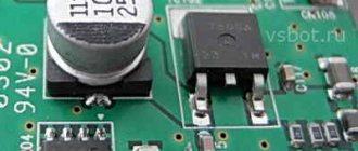
Rotators are used to weld flanges to steel pipelines. They give the unit mobility, improve access to the working area, and facilitate the welding process. During the welding process, the electrode remains stationary, the assembly gradually rotates around its axis. The rotator is used to finish cleaning the seams, priming and painting the flange assembly.
Important points when assembling a flange connection:
- it is necessary to fasten the disk perpendicular to the pipeline, a control triangle and a probe are used for checking, the permissible deviation is 2% of the outer diameter;
- the axes of the bolt holes on the two disks must coincide; alignment is checked with a level and plumb line. Permissible deviations: a) 1 mm for holes with a diameter of 18 to 25 mm; b) 2 mm for diameters up to 41 mm.
The “boat” technique is used for connections without backlash; the edges are welded to a great depth. If the gap is within 1.5 mm, welding is performed with transverse oscillatory movements, the electrode is held at an angle of 30° to the surface of the pipe. A backlash of 4–5 mm is formed using a fillet seam with large stitches (cathetes). If the gap is large, two penetrations are allowed.
The width and height of the roller are determined by the size of the rolled product. A thick surfacing bead is made on the outside of the pipe, and a minimal one on the inside so that it does not change the flow cross-section.
Welding of pipeline parts
#1 grindush
- Name: Skrementov Konstantin Sergeevich
- Field of activity: Repair service
Actually, the essence of the problem: on the section of the technological petroleum product pipeline within the pumping station there are sections with non-standard pipeline elements that must be replaced. On a narrow section of the pipeline there is a sequential transition from a larger diameter to a smaller one two times in a row. The pipeline profile in this place excludes the possibility of inserting a pipe coil between two diameter transitions. And, as far as my memory serves me, welding of pipeline parts and shut-off valves of various thicknesses and diameters is possible by welding an adapter ring from a pipe of the same diameter and properties.
On the other hand, “Based on the inadmissibility of overlapping heat-affected zones of welds, they should be located no closer than 100 mm from each other (at a minimum) and according to the norm = depends on the thickness of the metal. "(taken here: https://www.proekt-gaz.ru/forum/2-766-1). And one more thing: PB 03-585-03
RULES FOR CONSTRUCTION AND SAFE OPERATION OF TECHNOLOGICAL PIPELINES
6.2.6. The distance from the transverse welded joint to the edge of the support or suspension should provide (if necessary) the possibility of its heat treatment and control. The distance from the fitting or other element with a fillet (T) weld to the beginning of the bent section or transverse weld of the pipeline must be no less than the outer diameter of the pipe, but not less than 50 mm for pipes with an outer diameter of up to 100 mm. For pipes with an outer diameter of 100 mm or more, this distance must be at least 100 mm. The length of the straight section between the welds of two adjacent bends must be at least 100 mm for a nominal diameter of less than 150 mm and 200 mm for a nominal diameter of 150 mm and above. When using steeply curved bends, it is allowed to place welded joints at the beginning of the curved section and weld bends without straight sections to each other. 6.2.7. The distance between adjacent welded joints and the length of the ring inserts when welding them into the pipeline must be at least 100 mm.
The question arises: Is there a direct reference to a clause in a regulatory document that strictly prohibits welding two pipeline parts together, or, conversely, that allows such things to be done? The question is from the field of pipeline transport of oil and petroleum products, but any useful thoughts from other industries are welcome.
source
Weld quality control
To check the tightness of the flange fastening, an ultrasonic method is used. The seam is checked:
- on cracks;
- the presence of slag inclusions, sagging, cuts;
- Burns, craters, and porosity are unacceptable.
Flaw detection is also carried out by metallography. At critical connections, the quality of welding of flanges to pipes is checked by radiographic non-destructive testing.
Knowing the intricacies of fixing the flanges, if necessary, you can independently weld the disk to a section of the plumbing system.
Welding flanges to steel pipelines with a diameter of 100 mm
LOCAL RESOURCE STATEMENT GESN 22-03-014-03
| Name | Unit |
| Welding flanges to steel pipelines with a diameter of 100 mm | 1 flange |
| Scope of work | |
| 01. Attaching flanges to the ends of pipes. 02. Welding flanges. |
The price takes into account the work requirements for 2000
(Moscow prices), calculated according to the GESN model of
2009
. Indexation of translation into current prices must be applied to the cost.
You can go to the pricing page, which is calculated based on the standards of the 2014 edition with additions 1 To determine the composition and consumption of materials, machines and labor costs, GESN-2001 was used
| № | Name | Unit Change | Labor costs |
| 1 | Labor costs of construction workers Level 5 | person-hour | 0,7 |
| 2 | Labor costs for drivers (for reference, included in the price of the EV) | person-hour | 0,39 |
| Total labor costs for workers | person-hour | 0,7 | |
| Workers' compensation = 0.7 x 11.08 | Rub. | 7,76 | |
| Payroll for drivers = 5.26 (for calculating invoices and profits) | Rub. | 5,26 |
OPERATION OF MACHINES AND MECHANISMS
| № | Cipher | Name | Unit Change | Consumption | Article number Rub. | Total RUB. |
| 1 | 150202 | Two-station welding units for manual welding on a tractor 79 kW (108 hp) | mach.-h | 0,39 | 133,97 | 52,25 |
| Total | Rub. | 52,25 |
| № | Cipher | Name | Unit Change | Consumption | Article number Rub. | Total RUB. |
| 1 | 101-1513 | Electrodes with a diameter of 4 mm E42 | T | 0,00029 | 10315 | 2,99 |
| 2 | 507-9508 | Flat steel flanges | PC. | 1 | 0,00 | |
| Total | Rub. | 2,99 |
TOTAL BY RESOURCES: 55.24 RUR.
TOTAL PRICE: 63.00 RUR.
Look at the cost of this standard at current prices open page
Compare the price value with the value of FER 22-03-014-03
To draw up an estimate, the price requires indexation of the transition to current prices. The price is based on the GESN-2001 standards, as amended in 2009.
in
2000
.
To determine intermediate and final price values, the DefSmeta
Product classification
The general structure of the part is a ring and a plate with holes along the edge. To ensure tightness between the elements, a rubber gasket is also installed in accordance with the purpose of the pipeline - acid-resistant, heat-resistant. The ring and plate are connected using fasteners - bolts with nuts or studs.
According to GOST, there are several different types of flanges. According to the drawings, their differences are clearly visible.
Accordingly, welding of parts to the pipeline is carried out somewhat differently.
- Collar type – a characteristic feature is a welded neck in the form of a conical concentrator. This shape allows the pressure to be distributed more evenly. The collar model is designed for communications with high pressure and high temperature media. Welded with a continuous or V-seam.
- Bell-shaped - used on pipes with a small diameter operating under high pressure. The downside of the product is some instability to corrosion. The socket part is welded from the outside using a fillet weld. A clearance of 1.6 m must be maintained to neutralize the effect of thermal expansion.
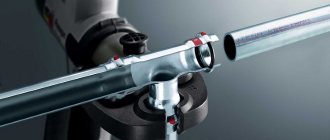
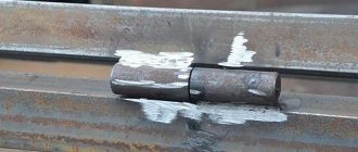
- Through - or freely rotating. Welding of a through pipe to a flange according to GOST is not carried out, since the through option is used specifically so that the part can be replaced as necessary. The photo shows a through flange connection.
- Blind - a flat disk with holes. This device is necessary for plugging the ends of the pipeline. The element is not dismountable, but it is only fixed and not welded.
- Flat – ring and plate are the same size. Welding a flat flange to a pipe involves attaching a ring while the plate remains free to rotate. It can withstand pressure up to 2.5 MPa.
- Slip-on - to use it, the edges of the pipes must be perfectly straight, so it is not as versatile as collar models. The cap is welded with fillet welds on the outer and inner sides.
- Threaded - used on small diameter pipelines where it is possible to make a thread. Welding is used extremely rarely during its installation.
Technical recommendations
It is not recommended to weld a flat flange to an outlet without a coil, because the connection is made with a fillet weld - the result is a rigid structure that experiences complex loads. The tightness of the seam under certain conditions (for example, during thermal expansion when a hot medium is supplied) may be broken.
Collar (“with a skirt”) and free (with flange) flanges are welded with a simpler and more reliable butt weld - a connection that is resistant to tensile and compression loads is obtained.
When connecting a flange to an outlet or transition, it is necessary to provide for the possibility of free insertion/removal of bolts or studs when assembling/disassembling the flange.
source
Welding a flange to a pipe according to GOST
The welding technology is basically the same, with the exception of fastening the pipes. However, it is necessary to take into account the complexity of the design - it is recommended to clarify the drawings and compliance with the fastening requirements.
In most cases, it is necessary to maintain a gap in the joint. If backlash is not needed, the boat welding technique is allowed. If the backlash should be large - more than 4-5 mm, the product is welded with fillet welds. All this, of course, affects prices.
The dimensions of the seam depend on the pipeline. The width of the internal seam is usually equal to the wall thickness, the height is from 0.5 to 1 cm, which is determined by the cross-section of the pipeline. The outer seam requires more metal deposition, so it is somewhat asymmetrical.
Welding is done from 2 sides: first from the outside, and then, to seal the seam, from the inside. This method is most suitable for flat flanged parts. Welding on one side is carried out if the product is butt welded, as in the case of a collar flange.
Not every device for welding flanges to pipes is suitable. The Lisitsyn and Bondarenko apparatus is usually recommended. When welding, the electrode remains stationary here, and the pipeline rotates.
The video discusses the welding process in more detail.
Subtleties of the process
Technological features of the welding process depend on the type of flanges. Flat flanges are mounted only on straight sections of pipe - unlike collar models, they cannot be welded to bends. Differences in welding methods for flat and collar flanges are explained by different types of seam joints (butt or corner) and the nature of the structure being formed. Flat-flange connections are made with a fillet weld, forming a rigid structure, which, when high-temperature substances are supplied, can collapse due to the difference in the coefficients of thermal expansion. Collar flanges are welded with a butt weld that can withstand significant temperature fluctuations.
PC Ferrum Hand employs qualified welders, craftsmen, engineers and technologists. They are certified by NAKS (state body for welding control), confirmed by issued certificates. The work is carried out using certified welding equipment. If the customer needs to weld a flange according to all the rules, we will do it professionally, quickly, and at affordable prices.
Sale of rolled metal in St. Petersburg and Leningrad region
Source
What is the flange for?
Basically, flanges are intended for forming quick-release flange connections on pipes. Unlike welding, this design makes it possible to quickly connect or remove individual parts of the pipeline, for example, to check the condition of the pipe in individual sections, install taps, sensors, to drain water or to connect equipment (the same heat exchanger). The flanges are welded onto the ends of the pipes and connected to each other with bolts and studs complete with a counter flange. Gaskets made of rubber or other materials must be placed between them.
Flanges are used in various industries and utilities for the hermetically sealed connection of a certain section of the pipeline to various technological devices and devices for the purpose of supplying and discharging media, as well as for joining individual sections of the pipe to each other.
Classification. Flange types
Flanges in different countries are manufactured to standards that correspond to the specific regulations adopted in those countries. This can be GOST (for Ukraine DSTU ISO 7005-2:2005 (ISO 7005-2:1988, IDT). Metal flanges.)), DIN or TU. The shapes are divided into round and square. Two significant groups of flanges can be identified:
- for fittings
- for vessels and apparatus.
The following are the most commonly used types of flanges:
Welded flange collar, slip-on, socket, freely rotating, threaded, blind flange. Let's briefly go through each of them.
Collar flange
They have a characteristic welded neck in the form of a conical concentrator, smoothly transitioning to the pipe wall. It ensures distribution of the pressure of the supplied substances through the conical hub. Used for pipelines with high pressure or high/low temperatures. The collar flange must be welded using a V-shaped or continuous seam.
Flange pipe Most often used for secondary tasks as a flange backing for inexpensive flanging.
Socket flange
Designed for small-sized pipes with high pressure. Their service life is twice as long as that of welded slip-on flanges. Disadvantages include the possibility of ruptures and susceptibility to corrosion.
Welding of socket flanges is carried out only from the outside with a fillet butt weld, while it is necessary to leave a small gap of approximately 1.6 mm to compensate for the effect of thermal expansion (indicated “X” in the picture).
Slip-on flange
Requires smooth pipe edges when connecting. Their service life is two to three times less than that of collar flanges. due to Welding of cap flanges is carried out on the outer and inner sides using fillet welds. In order not to damage the flange surface during welding, it is necessary to have a gap of 3 mm between the end of the pipe and the inner edge of the flange.
Rotating flange
Rotates freely on the pipe, not welded. The rotating flange can be easily removed and replaced if necessary. Can be fastened with opposite bolt connections.
Regulations
For all of the above cases, clauses 3.2.14, 3.2.15 and 3.2.16 of the Rules for the Construction and Safe Operation of Process Pipelines (PB 03-108-96) are applicable. They say the following:
Design and work must be carried out in such a way that in the future it is possible to control the weld and, if necessary, carry out heat treatment. If the project uses pipes with a metal thickness of less than 8 mm, then at least 50 mm should be retreated from one weld to another, if more than 8 mm - 100 mm. In all other cases, there must be a distance between welds that is three times the nominal thickness of the material.
If the project has supports, then if the pipe wall thickness is up to 50 mm, 50 mm should be removed from them, and more than 50 mm - 200 mm.
To make a weld, a distance of 50 mm should be taken from the beginning of the elbow bend - this is for pipelines with an outer pipe diameter of up to 100 mm and at least 100 mm - for outer pipe diameters of more than 100 mm.
Each specific case is considered individually if it is impossible to maintain the distances specified in the first two paragraphs. The issue is resolved by the designer or a specialized research organization, taking into account technological parameters.
There is also PB 10-573-03 (for steam and hot water pipelines). Here we are interested in paragraphs 2.3.8 and 2.3. They allow welding joints of steeply curved bends at the beginning of the rounding. They can be welded directly, without additional straight sections.
Summarizing the above, it turns out that if certain conditions are met, it is possible to weld a flange to an outlet without a coil. It is worth considering some technical points.