Lecture 1 BASIC CONCEPTS ABOUT CUTTING METAL
1. Cutting tool and cutting process
The cutting process is the processing of metals by removing chips. The chips are removed with cutting tools. The main element of any cutting tool is a cutting wedge, which, with relative movement, cuts into the workpiece and removes a layer of metal in the form of chips.
To find out the role of the main elements of a cutting tool, let's consider the simplest case of cutter operation.
Let us assume that a rectangular heat-treated block A is fixed in the support of a cross-planing machine (Fig. 1), and workpiece B
When moving the support with the block L fixed in it in the direction of the arrow and from the workpiece
B
, a layer of metal with a depth of t will be removed.
Rice. 1. Scheme of operation of the cutter.
Thus, heat-treated block L will cut the softer metal of workpiece B.
But cutting under such conditions will be difficult, since the lower plane of the block will rub strongly against the surface of the workpiece, and the metal in front of block A will be greatly deformed.
If the lower plane of the block A is ground at an angle a, and the front plane is directed at an angle g, then cutting will be easier. Consequently, by changing the shape of the bar, we can significantly reduce both its friction on the cutting surface and the deformation of the metal during the formation of chips.
From Fig. 5 it can be seen that with increasing angles a and g, the cutting process will proceed more easily, since the sharper the wedge, i.e., the smaller the angle formed by the front and rear planes, the less force is required to cut it into the metal. The angle formed by the front and rear planes is called the cusp angle and is denoted by the Greek letter b. Thus, the magnitude of the applied force will depend on the magnitude of the sharpening angle: the smaller the sharpening angle b, the easier the wedge will penetrate into the metal, and, conversely, the larger the sharpening angle, the more difficult it is for the wedge to cut into the metal. But a decrease in the sharpening angle b leads to mechanical fragility of the cutter. This limits the increase in the magnitude of angles a and g .
During turning, the chip removal process occurs as a result of a combination of two simultaneous working movements, one of which is rotational, and the second is translational. The rotation of the workpiece v (Fig. 2) is called the main movement, and the movement of the cutter S relative to the workpiece is called the feed movement.
During the cutting process, the following three surfaces are distinguished on a part: 1 - the machined surface, 2 - the cutting surface and 3-
treated surface (Fig. 2).
The machined surface is the surface of the part that is subject to processing, i.e., from which chips are removed.
The cutting surface is the surface that is formed on the part directly by the cutting edge of the cutter. Chips are cut off from it with each revolution of the part.
The surface of a part obtained after removing chips is called machined.
2 Elements of cutting mode
Elements of the cutting mode are:
depth of cut
· feed
· cutting speed.
Depth of cut—
this is the thickness of the metal layer cut by the cutter in one pass (Fig. 3).
Depth of cut is designated by the letter t
and is measured in millimeters as the linear distance between the machined and machined surfaces. When turning, the cutting depth is measured in the axial plane of the part and is equal to:
where D -
diameter of the treated surface,
mm, d -
diameter of the treated surface,
mm.
Fig.3 Cross section of the metal layer being cut
By filing
when turning, the movement of the cutter along the machined surface during one revolution of the part is called.
Feed is measured in millimeters per revolution (mm/rev)
and is denoted by the
letter S. Most often, when turning, longitudinal (along the axis of the part) and transverse (across the axis) feeds are used. Typically, feeds are continuously uniform, i.e., for each revolution of the part, the cutter moves the same amount.
Depth of cut and feed characterize the main dimensions of the chip.
Width
cut layer (chips) is the distance between the machined and machined surfaces, measured along the cutting surface.
The chip width is designated by the letter b
and is measured in millimeters.
Thickness
cut layer is the distance measured in the direction perpendicular to the chip width between two successive positions of the cutting surface during one revolution of the part.
Thickness is measured in millimeters and is designated by the letter a
.
The nominal area
none of the river section
of the chip is the product of the depth of cut t and the feed S or the width of the chip b and the thickness
a:
Depth of cut t, feed per revolution S ,
The width
b
and thickness
a
of the cut layer are related to each other by the following dependencies:
b
=
a
= S sin j
With a change in the main angle j, the thickness and width of the chip (cut layer) change at constant values of cutting depth and feed. The smaller the entering angle, the thinner but wider the chips, and vice versa.
At the entering angle j=90°, the chip width is equal to the depth of cut ( b = t ),
and the thickness is the feed
(a
= S). In all cases, when the depth of cut and feed are constant, the area of the cut layer remains constant.
Cutting speed-
the path of movement of the cutting edge relative to the machined surface per unit of time. When turning, the cutting speed is measured in the plane of rotation of the part as the peripheral speed of the machined surface, which is most distant from the axis of rotation. The cutting speed is denoted by the letter v and is measured in meters per minute, i.e.
v
=
or after abbreviation:
v
=
where D—
diameter of the workpiece surface being machined,
mm;
P
— number of revolutions of the workpiece per minute. To set up a machine for a given cutting speed, you need to determine the number of revolutions of the machine spindle. The spindle speed is calculated using the following formula:
If the machine does not have such a number of spindle revolutions, then you should take the nearest lower number of revolutions and recalculate the actual cutting speed at this number of revolutions.
3 Geometric parameters of cutters
Cutters consist of a holder and a head. The head is the cutting part of the cutter. The sharpening angles of the cutter head determine its geometric parameters, the correct choice of which determines the durability of the cutter, labor productivity and the quality of the machined surface.
The cutting part of the cutter is formed by sharpening three surfaces: the front 1
(Fig. 4), rear main
4
and rear auxiliary
3.
In most cases, the cutter surfaces are planes.
Physico-mechanical fundamentals of metal cutting
Metal cutting – technological processes of metal processing by removing chips, carried out with cutting tools on metal-cutting machines in order to give parts specified shapes, sizes and quality of surface layers.
Rice. 1. Types of cutting processing : Dr – cutting movement; DSpr, DSp, DSv, DSkp – longitudinal, transverse, vertical and circular feed movements, respectively; 1 – surface to be treated; 2 – cutting surface; 3 – processed surface
During the processing process, allowance in the form of chips is removed from the workpiece by the following types of cutting processing: turning, planing, drilling, milling, grinding (Fig. 1). Almost all parts of machines and mechanisms acquire their shape and dimensions in accordance with the drawing after processing their blanks by cutting.
Turning is a method of processing bodies of revolution. The main movement during turning is the rotational movement of the workpiece Dr. The feed motion is imparted to the cutting tool.
The rectilinear feed movement of the cutter can be directed along DSpr or across DSP (Fig. 1) of the axis of rotation of the product, respectively, and the feed is called longitudinal or transverse.
The following types of work can be performed using the turning method: turning external and boring internal surfaces, trimming the end surface, shaped turning with a shaped cutter and copy turning using a carbon copy.
Metal planing is the process of cutting a layer of material from a workpiece with a cutter during a translational main movement. Various machines are used for processing metals by planing: cross-planing, longitudinal-planing, edge-planing, planing-slotting and others. Planing on cross-planing machines is performed with a cutter that performs a rectilinear reciprocating movement Dr, feeding is carried out by moving the workpiece DSP (Fig. 1). When working on longitudinal planing machines, the reciprocating cutting motion is imparted to the workpiece, and the feed motion is transmitted to the cutter. In planing machines, the cutting movement consists of working and idle strokes; The feed movement of these machines is intermittent.
By drilling, holes are made in the solid material of the workpiece or the size of existing holes is increased. When processing holes on drilling machines (Fig. 1), the main movement is the rotation of the tool Dr, and the feed movement DSв is the movement of the tool vertically along its axis. You can also drill on lathes, turrets, boring machines, milling machines, automatic lathes, etc. To obtain more accurate holes, after drilling they must be countersinked, bored or reamed.
Milling is used for processing planes, grooves with a straight and helical direction, splines, ledges, gears, cutting workpieces, forming threads, and obtaining shaped surfaces. Milling is carried out with multi-blade tools - cutters, which perform a rotational movement, which is the main Dr. The feed movement DSpr, perpendicular to the axis of rotation of the tool, is produced by the machine table with the workpiece fixedly fixed on it (Fig. 1).
Grinding ensures high cleanliness of the processed surface and high dimensional accuracy of the processed parts. When grinding, the main movement Dr is the rotation of the grinding wheel 2 (Fig. 1). The feed movement is usually combined and consists of several movements. For example, with external circular grinding this is the rotation of the workpiece DSkp, with longitudinal grinding it is its movement relative to the grinding wheel DSpr.
Machining determines the quality of manufactured machines, their accuracy, durability, as well as reliability and cost. Despite the fact that methods for obtaining workpieces and processing them on metal-cutting machines are constantly being improved, the labor intensity of machine tools in mechanical engineering constitutes the largest part, reaching 30–50% of the total labor intensity of machine manufacturing.
The cutting process is a complex of complex phenomena that depend on the physical and mechanical properties of the material being processed, the quality of the cutting tool, cutting conditions, machine condition, and the rigidity of the technological system.
Rice. 2. The workpiece and the scheme for processing it with a turning tool : a – allowances, allowances for the dimensions of the shaft workpiece; b – longitudinal turning
Depending on the material, shape and size of the part processed on the machine, the main types of metal workpieces are: castings from cast iron, steel and non-ferrous alloys; forgings and stampings made of steel and non-ferrous alloys; long rolled steel and non-ferrous alloys, which arrives in the form of rods and is cut into individual blanks.
The correct choice of structural material should ensure the operational properties of the part, its durability, maintainability and ability to be recycled. When designing a part, the designer must know what technological processes will be used in the manufacture of the workpiece and its subsequent processing. In this case, the technological properties of the material can determine in advance the manufacturing technology of the workpiece and its subsequent thermal and mechanical processing.
For example, if the shaft blank (Fig. 2, a) is a casting or forging, then the drawing shows the allowances, laps and operational dimensions of the shaft.
Shaft processing, for example, is carried out by turning. The cutting process is represented by a processing diagram (Fig. 2, b), which conventionally depicts the workpiece 2 being processed, its fastening in the working fixture of the machine 3, the cutting tool 1 in the position corresponding to the end of processing.
The main movement Dr during cutting is the movement that determines the rate of deformation and chip separation.
Feed motion Ds is the motion that ensures continuity of cutting of the tool cutting edge into the workpiece material. These movements can be rotational, translational, reciprocating, continuous or intermittent (GOST 25762–83, GOST 25761–83).
Using symbols, they show the nature of cutting movements (cutting movement Dr and feed movement Ds), their technological purpose. The feed movement in this case is longitudinal DSpp (Fig. 2, b). During the cutting process on the workpiece, the machined surface 4 is distinguished, from which the chips are removed; cutting surface 5 formed as a result of the action of the main cutting edge of the tool; processed surface 6 obtained during the processing process.
1.1 Cutting mode
When assigning the cutting mode, the speed of the main cutting movement, feed rate and depth of cut are determined. Cutting speed V is the path of the point of the cutting blade of the tool relative to the workpiece per unit time in the direction of the main movement. Cutting speed dimensions: for blade processing – m/min, for abrasive processing – m/s.
If the main movement is rotational (Fig. 1), then for blade processing the speed of the main movement, m/min:
for grinding, m/s:
V = πDn/1 000,
V = πDn/(1 000 60),
where D is the largest diameter of the workpiece surface being machined or the diameter of a rotating tool, mm; n – workpiece (tool) rotation speed, rpm.
If the main movement is reciprocating, and the working and idling speeds are different, the average speed, m/min, is equal to
V = (K + 1)Lm/1 000,
where K = Vр.х/ Vx.x – coefficient of the ratio of the working speed Vр.х to the idle speed Vx.x; L – design stroke length of the cutter, mm; m is the number of double strokes of the cutter per minute.
The feed movement speed (feed) S is the path of the tool cutting edge point relative to the workpiece in the direction of the feed movement during one stroke of the workpiece or tool. There are:
- feed per minute (minute) Sm – movement of the cutting tool per minute, mm/min;
- feed per revolution So – movement of the cutting tool per revolution of the workpiece or tool, mm/rev;
- for multi-tooth tools – feed per tooth Sz – movement of the cutting tool during rotation by an angle equal to the angular pitch of the teeth, mm/tooth;
- feed per double stroke S2x – movement of the cutting tool in one double stroke, mm/2x.
Depth of cut t – the shortest distance between the machined and machined surfaces, mm.
When turning (Fig. 2, b) the cutting depth is equal to
t = 0.5(Dз – d),
where Dз and d are the diameters of the workpiece and the machined surface, respectively, mm (Fig. 3, b).
1.2 Elements and parts of a turning straight cutter
A turning straight cutter (Fig. 3) consists of a working part (head) 2 and a body (rod) 3 (GOST 25751–83). The cutter body serves to install and secure it in the cutter holder. The working part of the cutter is formed during sharpening and contains the following elements: front surface 4 (the surface along which the chips flow); main rear surface 7 (it is most developed and directed along the feed movement); auxiliary rear surface 1 (directed against the feed movement).
The intersection of the front and main flank surfaces gives the main cutting edge 6, the intersection of the front and secondary flank surfaces gives the auxiliary cutting edge 5.
The cutting edges intersect at the tip of the cutter 8. The location of the surfaces and edges of the cutter is determined by its sharpening (tool geometry). To determine the angles at which the tool elements are located, coordinate planes are introduced.
Rice. 3. Turning cutter, its parts and elements : 1 – auxiliary rear surface; 2 – cutter head; 3 – cutter body; 4 – front surface; 5, 6 – auxiliary and main cutting edges, respectively; 7 – main rear surface; 8 – tip of the cutter
Rice. 4. Coordinate planes of the through cutter : Рv – main plane; Рn – cutting plane
Three coordinate systems are considered: instrumental, static and dynamic. In the instrumental coordinate system, a tool is considered as a geometric body. In a static coordinate system, the main motion speed is nonzero, and the feed motion speed is zero. In a dynamic coordinate system, the velocities of the main movement and the feed movement are different from zero.
In Fig. Figure 4 shows the coordinate planes of a turning cutter in a static coordinate system. The main plane Pv is parallel to all possible directions of feed movement for a given processing method. The cutting plane Pn passes through the main cutting edge tangent to the cutting surface.
1.3 Tool geometry and its influence on the cutting process and processing quality
The geometry of the cutting part of the tool in a static coordinate system is considered using the example of a turning cutter (Fig. 5).
Rice. 5. Cutter angles in a static coordinate system : Dr – cutting movement; Ds – feed movement; Pv – main plane; Рn – cutting plane; Рτ – main cutting plane; α, γ – main rear and front angles; φ, φ1 – main and auxiliary plan angles; λ – angle of inclination of the main cutting edge
Principal angles are considered in the principal cutting plane Рτ. The main cutting plane Рτ passes through the main cutting edge perpendicular to the cutting surface. The main clearance angle α is the angle between the tangent to the main clearance surface at the considered point of the main cutting edge and the cutting plane. The presence of the angle reduces friction between the machined and main flank surfaces, which increases tool life. However, increasing the angle too much will reduce the strength of the cutting blade. The angle is in the range of 5–10° and is selected depending on the elastic properties of the material being processed. For those types of processing in which the feed speed is commensurate with the speed of the main movement (thread cutting), the angle is selected in the range of 8–14°. The main rake angle γ is the angle between the main and front surfaces. It can be positive (if the front surface is located below the main plane), zero (the front surface coincides with the main plane) and negative (if the front surface is located above the main plane).
The size of the angle has a great influence on the cutting process. As the angle increases, the deformation of the cut layer decreases (it is easier for the cutting wedge to cut into the metal), the conditions for chip flow improve, the cutting forces decrease, and the quality of processing improves. However, an excessive increase in the angle leads to a decrease in the strength of the cutting blade, increased wear of the cutting blade due to chipping, and deterioration of heat removal from the tool.
When processing low-carbon and low-alloy steels with high-speed tools, the angle γ is chosen within the range of 12–18°. When processing viscous materials, the angle is increased, and when processing brittle and hard materials, it is reduced down to negative values.
Plane angles are considered between the direction of feed movement and the projection of the corresponding cutting edge onto the main plane. The main angle φ is the angle between the projection of the main cutting edge onto the main plane and the direction of feed movement (Fig. 5). The plan angle determines the parameters of the transition cone between the processed cylinders and the angle of the chamfers, i.e., it is selected by the designer. The angle mainly affects the roughness of the machined surface.
As the angle decreases, the roughness decreases, at the same time the thickness decreases and the width of the cut layer increases, therefore, the cutting force and temperature per unit length of the cutting edge decrease, but the cutting force sharply increases in the direction perpendicular to the axis of the workpiece. Auxiliary angle φ1 – the angle between the projection of the auxiliary cutting edge onto the main plane and the direction of feed movement. As the angle decreases, the roughness of the machined surface decreases, while the strength of the cutting blade and its durability increase.
The inclination angle of the main cutting edge λ is the angle between the main cutting edge and the main plane drawn through the tip of the cutter. If the cutter tip is the highest part of the main cutting edge, λ > 0; if coincides with the main plane, λ = 0; if the tip is the lower part of the main cutting edge, λ < 0. As the angle increases, the quality of the machined surface deteriorates. But most often the choice of the magnitude and sign of the angle is determined by the direction of chip flow. At negative values of the angle λ, the chips flow in the direction of feed movement, which is safe when working on universal machines. For positive values of this angle, the chips flow in the direction opposite to the feed movement. This is safe when working on machines with automatic and semi-automatic cycles. Positive angles are used when machining holes to ensure that chips exit the hole.
1.4 Physical foundations of the metal cutting process. Chip formation
Metal cutting is a complex process of physical and chemical interaction between the cutting tool, the workpiece and the environment. The cutting process can be simplified in the form of a diagram (Fig. 6, a). On the cutting edge of a real cutter, one can distinguish between the rounding of the blade BC and the wear area AB, so the real rake surface will be the BCF surface, and the real back surface will be GAB.
Rice. 6. Cutting process and types of chips : a – cutting diagram: Dr – cutting movement; BCF – front surface; GAB – posterior surface; BD – shear plane; BDEC – chip formation zone; OO – shear plane; О1О1 – direction of the axes of deformed crystals; h – elastic recovery of the treated surface; t – cutting depth; b, d – drain shavings; c – chipping chips; g, e – fracture chips
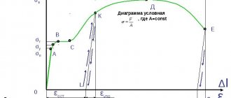
At the initial moment, the cutting blade of the tool is pressed into the metal, elastic deformations appear in the cut layer, which then turn into plastic. In the plane perpendicular to the path of movement of the cutter, normal stresses α arise, and in the plane coinciding with the path of movement of the cutter, tangential stresses τ arise.
On the front surface at point B, the tangential stresses τ reach their greatest value. Normal stresses initially act as tensile stresses (+σ), and then quickly decrease to zero and turn into compressive stresses (σ). The cut metal layer is plastically deformed. An increase in plastic deformations leads to shear deformation, i.e., displacement of parts of the crystal relative to each other.
Deformation occurs in the BDEC zone, called the chip formation zone. In the CE plane, the destruction of crystals occurs - the chipping of individual elementary volumes of metal, and a segment of chips is formed. Then the process is repeated.
Conventionally, it is believed that shear deformations occur in the OO plane, called the shear plane. It is located at an angle of 30° to the direction of movement of the cutter. The cut segment of the chip undergoes additional deformation due to friction against the front surface and curls into a spiral.
The metal structure in the BDEC zone differs from the structure of the underlying layers of the base metal. In the diagram (Fig. 6, a), undeformed layers are conventionally shown in the form of circles; as deformation occurs, the circles are flattened, and the major axis of the resulting ovals is located at an angle to the line OO. The nature of the deformation of the cut layer depends on the physical and mechanical properties of the metal being processed, the geometry of the cutting tool, processing conditions, cutting modes, etc.
When cutting, different types of chips are formed. At low speeds and large feed rates and cutting depths, the chips have pronounced shear planes and segments - these are shear chips (Fig. 6, c).
When cutting plastic materials at high speeds and small feed rates and cutting depths, the chips have the appearance of a continuous strip; on the side of the cutter, the surface of the strip is smooth; on the outer side, small sawtooth-shaped notches are visible - drain chips (Fig. 6, b, e). Such chips can injure the machine operator, they are difficult to remove from the machine, and difficult to transport to the processing department, so it is necessary to use special devices for crushing them (for example, chip-breaking grooves on the front surface of the cutter).
When processing brittle materials, plastic deformation is practically absent; the chips have the form of separate segments not connected with each other - fracture chips (Fig. 6, d, f).
As the cutting tool passes, the treated surface, due to the effects of elastic and plastic deformations, is elastically restored by the value h, and the structure of the surface layers differs from the structure of the core. The hardness of the surface layer will be higher than the hardness of the core, and a hardened layer will form. Pack size
other restoration of the treated surface, the hardness of the surface layer, the depth of the hardened layer and the stress diagram (Fig. 6, a) depend on the physical and mechanical properties of the metal being processed, the geometry of the cutting tool, processing conditions, and cutting modes. The greater the elastic-plastic properties of the processed material, the greater the depth of cut and feed used and the lower the cutting speed, the greater the elastic recovery of the processed surface, the hardness of the surface layer, and the deeper the spread of hardening.
1.5 Cutting forces
Cutting force is understood as the force of resistance to the movement of the cutting tool relative to the workpiece. The work of the cutting force is spent on elastic and plastic deformation of the metal, on its destruction, on the friction of the rear surface on the machined surface and on the friction of chips on the front surface of the cutting tool. The result of the resistance of the workpiece metal to the cutting process is the emergence of reactive forces acting on the cutting tool (Fig. 7, a).
Reactive forces are forces of elastic (Ру1 and Ру2) and plastic (Рп1 and Рп2) deformation, directed perpendicular to the rear and front surfaces of the tool, respectively, and friction forces (Т1 and Т2) along the rear and front surfaces. The vector sum of all these forces will give a unit cutting force over the cross section of the cutter. Having summed up the unit forces, we obtain the resultant cutting force P = Pp1+ Pp2+ Ru1+ Ru2+ T1+ T2. However, due to the variability of cutting conditions (heterogeneity of the structure of the metal of the workpiece, tolerances on the dimensions of the machined surface, etc.), the resultant cutting force P is variable in magnitude and direction, therefore, for calculations, it is not the force P that is used, but its projections on the given coordinate axes (Fig. 7, b):
P = Px + Ru + Pz.
The Ox axis is carried out in the direction opposite to the direction of feed movement, the Oz axis is in the direction of the main movement, the Oy axis is in the direction perpendicular to the machined surface. Received projections: Pz – the main component of the cutting force; Рх – tangential (axial) component of the cutting force; Ru is the normal (radial) component of the cutting force.
The use of cutting force components is convenient. Firstly, the parameters of the main movement mechanism of the machine are determined by force Pz; the parameters of the feed mechanism of the machine are determined by force Pho; force is one of the main elements in calculating processing accuracy. Secondly, the ratio of cutting force components for various processing schemes and various pairs of “workpiece material – material of the cutting part of the tool” is quite stable. For example, for external turning of low-alloy steels with a high-speed tool, the ratio Pz: Ru: Px is in the range of 1: (0.4–0.6): (0.2–0.4). The main component of the cutting force Pz is determined by the empirical formula
Pz = CPtXрSYрVZрК1К2 – Ki,
where CP is a coefficient that takes into account the physical and mechanical properties of the material being processed; t – cutting depth, mm; S – feed, mm/min; V – cutting speed, m/min; exponents Xp, Yp, Zp and coefficients K1, K2, Ki take into account factors not included in the formula.
Rice. 7. Cutting forces : a – flat system of forces; b – decomposition of cutting force into components; Ру1Рп1, – reactive forces of elastic and plastic deformation along the front surface; Ру2, Рп2 – reactive forces of elastic and plastic deformation along the rear surface; Т1, Т2 – friction forces; P – cutting force; Pz, Px, Ru – respectively the main, axial and normal components of the cutting force; Dr – cutting movement; Ds – feed movement
Similar formulas exist for calculating other components of the cutting force.
1.6 Wear and durability of cutting tools and lubricating and cooling process media
All physical and chemical processes that occur when cutting metals lead to wear of the cutting tool:
- friction of chips on the front surface;
- friction of the machined surface against the back surface of the tool;
- high temperature and high pressure in the cutting zone;
- oxidation of the tool front surface material.
Wear on the front surface is distinguished - the formation of a hole of width b; as well as wear on the rear surface in the form of a ribbon of width h (Fig. 8).
For different tool materials and different cutting conditions, tool wear occurs at different rates, and some types of wear may prevail over others. For example, when turning with a high-speed steel cutter and producing thin chips less than 0.15 mm thick, wear on the main flank surface predominates.
Rice. 8. Wear and durability of cutting tools : tool wear on the back (hз) and front (b) surfaces
When turning at high speed and when cutting thick chips more than 0.5 mm thick, wear on the rake surface predominates; and when cutting chips with a thickness of 0.15 to 0.5 mm, simultaneous wear occurs along the front and rear surfaces.
To determine the optimal operating time of a tool, the dependence of tool wear on its operating time is studied. The operating time of a tool from regrinding to regrinding is called “lifetime”.
Physical durability Tf – tool operating time before emergency wear. But during finishing machining, wear can significantly affect the machining accuracy due to a decrease in its actual overhang. Therefore, for finishing machining, dimensional stability Tr is prescribed (the tool wears out to a value at which wear has a significant effect on machining accuracy).
In addition to physical and dimensional durability, there is a distinction between minute durability Tm - the period of work in minutes, piece durability Tsht - the number of processed parts before regrinding the tool.
The cutting speed has the greatest influence on tool life, so the dependence is most often used in tool life calculations
T = C/Vm,
where C is a constant value; V – cutting speed; m – indicator of relative resistance.
Modern lubricating-cooling technological media (LCTF) are complex multicomponent compounds of petroleum and chemical production products. The purpose of using COTS is to increase tool life, reduce cutting force, improve the quality of the machined surface, and remove chips from the cutting zone. The action of COTS is based on the following effects: lubricating, cooling and washing.
Lubrication effect – reduction of adhesion and friction forces on tool surfaces. A necessary condition for the manifestation of this effect is the ability of COTS to penetrate between contacting surfaces through capillaries and form films there that reduce the coefficient of friction. The cooling effect is a decrease in temperature in the contact zone of the cutting tool with the material being processed by reducing heat generation and increasing heat dissipation. The reduction in heat generation occurs due to the influence of COTS on the strength of the separated layer of material, increasing its fragility, and reducing the work spent on chip formation.
The intensity of heat removal mainly depends on the viscosity, thermal conductivity and speed of movement of the COTS, the temperature difference between the cooled surface and the COTS. The cooling intensity can be increased due to high-pressure COTS supply, COTS supply from the rear surface or through special channels made in the body of the tool, COTS supply in the form of fog. At the same time, COTS in the form of an emulsion or in the form of aqueous solutions have better cooling properties compared to oil COTS. The washing effect is to ensure the removal of chips, wear products of the cutting tool and decomposition products of COTS from the cutting zone. This effect is especially important when performing finishing operations.
1.7 Machining accuracy and surface quality
Processing accuracy means compliance of the manufactured product with the standard, i.e. his drawing. In relation to processed parts, the following are distinguished:
- dimensional accuracy, compliance of product dimensions with the drawing;
- geometric accuracy, compliance of shape, waviness and surface roughness with the requirements of the drawing;
- compliance of physical and chemical properties, structural state of surface layers (microcracks, tears, crushed structure);
- compliance of residual stresses in the surface and deep layers of the part with the requirements of the drawing, etc.
Dimensional accuracy. In accordance with the requirements of the International Organization for Standardization (ISO), in Russia the entire range of sizes and tolerances is divided into 19 qualifications (01–17). GOST 2789–73 fully complies with the international standardization recommendation ISO P468.
Geometric accuracy of the surface. The surface that bounds and separates the part from its surroundings is called the real surface; this surface is formed during processing and, unlike the nominal surface (the surface indicated in the drawing), has irregularities of various shapes and heights. The following errors of geometric accuracy are distinguished: macrogeometry (shape errors), waviness and microgeometry (roughness).
Shape errors are considered over large areas of the real surface (the ratio of the pitch of irregularities to their height is more than 1,000). This indicator refers to the conicality, ovality, and non-flatness of the treated surface. These parameters must comply with the requirements of the relevant Russian standards or the requirements of the drawing. Surface roughness is a set of irregularities that form the surface relief (the ratio of the pitch of irregularities to their height is less than 50) and considered within a certain section of it (base length). Waviness occupies an intermediate position between shape error and roughness. The actual roughness of the machined surface of the part is also determined by the physical and mechanical properties of the workpiece material and the vibrations of the AIDS technological system - “machine - fixture - tool - part”.
The surface layers of the part after mechanical treatment are plastically deformed, therefore the physical state of these layers is characterized by strain hardening (hardening) of the surface.
1.8 Processing performance
The number of parts produced per unit of time is called processing productivity and is calculated by the formula
Q = 1 / Tpcs.
Piece time Tsht consists of the main technological To,
preparatory and final Тп-з time and time for organizational and technical maintenance of the Trade.tech workplace. Basic technological time, i.e. the time spent directly on processing the surface (part) is equal to Т= Тм+ Тв+ Тх.х.
Machine time Tm, min is the time spent on chip removal:
Tm= L / (nSot),
where L – processing length, mm; n – rotation speed, rpm; So – feed per revolution, mm/rev; t – cutting depth, mm.
Auxiliary time TV is spent on moving the cutting tool with working feed: approaching, plunging, passing through areas that do not require chip removal, overtravel (guaranteed removal of the tool). The idle time Tx.x is spent on the rapid approach and removal of the cutting tool to the processing zone.
650
PROCESSING OF METALS BY CUTTING
PROCESSING OF METALS BY CUTTING, the process of separating (cutting) from metal. workpieces (parts) of the surface layer (allowance) in the form of chips using a cutting tool. It is used to give parts specified shapes and sizes, ensure the accuracy and quality of processed surfaces, as well as to remove low-quality or contaminated layers of material. O. m.r. – a set of interrelated processes of chip formation (as a result of various deformations), the formation of machined surfaces and wear of the working surfaces of cutting tools, accompanied by high heat generation. Basic methods of O. m.r. – turning, planing, drilling, reaming, broaching, milling, grinding, honing; characterized by different movements of the tool and the workpiece, ensuring movement of the tool relative to the workpiece, continuous or repeated removal of the allowance of the processed material through the formation of chips, as well as the design features of cutting tools. O. m.r. carried out using blade or abrasive cutting tools. on metal-cutting machines.
Basic characteristics of any type O.M.R.: cutting speed - the speed of the tool or workpiece in the direction of the ch. movement as a result of which chips are separated from the workpiece (m/min); depth of cut - thickness (mm) of the metal layer removed in one pass (the distance between the machined and machined surfaces, measured along the normal), feed - movement of the cutting edge of the cutter in mm per revolution of the workpiece. With O. m.r. the metal being processed receives large shear plasticity. deformations in the chip formation zone and even greater deformations in the narrow near-cutting zone of the plastic. chip contact with the tool. When cutting, a system of forces operates that can be reduced to a single resultant force; its components are important: Pz – cutting force acting in the cutting plane in the direction of the main movement; Ru is the radial component acting perpendicular to the workpiece axis (when turning) or to the tool axis (when drilling and milling); Px is the feed force acting in the feed direction. Forces Pz, Py, Px affect the operating conditions of the machine, tool and device, processing accuracy, roughness of the machined surface of the part, etc. The magnitude of cutting forces depends on the properties and structure of the material being processed, cutting mode, geometry and material of the cutting part of the tool, method cooling, etc. Important for O. m.r. has a choice of rational designs and parameters of cutting tools, tool materials, lubricating and cooling media, ensuring the lowest cost of processing while meeting the requirements for the accuracy and quality of machined surfaces, tool wear resistance, etc.
When cutting, decomposition materials are formed the following basic. types of chips: continuous (continuous) - when cutting plastic materials (e.g. mild steel, brass) with high cutting speeds and low feeds; chipping (elemental) - when processing hard steel and some types of brass with low cutting speeds and high feeds; fracture (consists of separate pieces) – when cutting low-plasticity materials (cast iron, bronze). The type of chip is influenced by geometry. cutting tool parameters and processing modes. When cutting plastic materials, an increase in feed leads to consistent transition from drain chips to elemental ones, and for brittle materials - from elemental chips to fracture chips. The chip type is practically independent of the cutting depth.
Under the influence of deformation during cutting, the surface layer of the processed material is strengthened (hardness increases and ductility decreases), and hardening of the processed surface occurs. Lubrication and cooling technologies the agents reduce the effective cutting forces, the depth and degree of hardening of the surface layer.
Under certain cutting conditions, a stagnation zone and a build-up (the material being processed sticks) is formed on the front surface of the cutting edge of the cutter, which has a wedge-shaped shape and increased hardness of the material being processed. The build-up changes the geometry of the cutting part of the tool, affecting the wear of the cutter and cutting forces.
Max. the temperatures of the tool surfaces and the corresponding cutting modes are limited by the permissible wear rates or wear resistance of the tool, as well as plasticity. deformations of the cutting blade under the influence of stress and temperature. When cutting steels with carbide tools, max. the temperature is 900–1000 °C, and when cutting difficult-to-cut materials (for example, heat-resistant alloys) it reaches higher values - approx. 1200 °C.
Fundamentals of the theory of O. m.r. developed by Russian scientist I. A. Time (1870), in the end. 19 – mid. 20th centuries Means. contributions to the development of cutting processing were made by K. A. Zvorykin (research of cutting forces), Ya. G. Usachev (methods for studying the chip formation process), N. N. Zorev (cutting mechanics), A. N. Reznikov (thermal physics of cutting), V. S. Kushner (thermomechanics of cutting), T. N. Loladze, M. F. Poletika (wear and wear resistance of tools during cutting), A. S. Vereshchaka (development of wear-resistant coatings), A. D. Makarov, S. S. Silin (determination of optimal cutting conditions), A. I. Markov, V. N. Poduraev (vibration during cutting), etc.
Due to the complexity of modeling the cutting process, rational cutting modes and parameters of cutting tools are determined based on empirical data. generalizations of experiments. and production data. When modeling technological process O. m.r. take into account the design temperatures, cutting forces, wear rates and wear resistance characteristics of cutting tools based on thermo-mechanical. approach. In the field of technological improvement. equipment prospects are associated with the creation of new, more durable and wear-resistant tool materials and coatings, as well as high-precision machining centers capable of carrying out various methods of metal cutting.
Machinability of materials by cutting and cutting properties of tools
Home » Articles » Professionally about metalworking » Metal cuttingWe recommend purchasing:
Installations for automatic welding of longitudinal seams of shells - in stock!
High performance, convenience, ease of operation and reliability in operation.
Welding screens and protective curtains are in stock!
Radiation protection when welding and cutting. Big choice. Delivery throughout Russia!
The process of processing materials by cutting consists in the interaction of two bodies - the workpiece and the cutting tool. In this case, the surface layer of the material cut from the workpiece is subjected to severe plastic deformation, as a result of which the cut layer in a partially or completely destroyed state is removed from the workpiece in the form of cut chips. New surfaces continuously appear on the workpiece and on the cutting chips during the cutting process.
The following basic requirements apply to cutting materials as a technological method for processing blanks of machine parts:
- high quality and precision of processed surfaces;
- high labor productivity;
- efficiency.
Fulfillment of these requirements depends on a complex of simultaneously operating factors, which can be divided into three main groups.
The first group includes factors related to the physical nature and structural state of the material of the workpiece being processed.
The second group of factors is determined by the properties of the material of the cutting part of the tool, its design and workmanship.
The third group includes factors that reflect the actual conditions of the cutting process.
When studying the cutting process, a number of interrelated parameters and characteristics were established that reflect various physical phenomena that occur during the interaction of the cutting tool with the workpiece being processed, and the course of which is influenced by the properties of the material being processed by cutting.
These parameters and characteristics are united by the general term machinability of a material by cutting, which refers to the property of materials to be processed by cutting. The main indicators of machinability can be both comparative and absolute.
The indicators that determine the essence of the machinability of a material by cutting include:
- cutting force (torque) of the processed material, determined in comparison with the cutting force of the reference material (for metals, this is usually steel 45) and measured under equal cutting conditions;
- effective cutting power compared to the effective cutting power of the reference material;
- chip shrinkage (longitudinal and transverse) as a measure of plastic deformation necessary for its cutting and the formation of new surfaces on the workpiece;
- the presence or absence of a tendency to form a build-up on the surface of the tool under equal cutting conditions, as well as the shape of the build-up;
- the quality of surfaces processed by cutting under equal and optimal conditions, assessed by roughness (Surface roughness is a set of surface irregularities with relatively small steps that form its relief) and residual stress (Residual stresses are internal stresses that persist over time, the main cause of which is heterogeneity deformations at different points of the body due to uneven temperatures or plastic deformations) in the surface layers of the manufactured part;
- the wear rate of the tool material compared to its wear rate when cutting the reference material;
- heat released during deformation of the material of the cut layer and during the interaction of the rubbing surfaces of the tool and the workpiece, as well as the distribution of this heat between the chips, the material being processed and the tool;
- the type, shape and size of the cut chips, which determine the convenience of its removal, storage and transportation, the possibility of forced curling and breaking of the chips, as well as the safety of the machine operator;
- energy consumption for cutting a unit mass of chips.
Quantitative assessments of the listed indicators of the machinability of a structural material of a given chemical composition and structural state are determined depending on its hardness, tensile strength and elongation, the coefficient of friction paired with the tool material, the wear properties of the tool blades, thermal conductivity, etc. In real production conditions, the listed properties of materials are not constant due to deviations in the chemical composition and heterogeneity of the structure.
In addition, the characteristics of the cutting process, reflecting the interrelated physical phenomena in the chip formation zone, change depending on the cutting conditions, progressive wear of the tool, etc. Based on this, a comparison of quantitative estimates of machinability, for example, by tool life (The durability of cutting tools is understood as the duration ( in minutes) of direct cutting from regrinding to regrinding with the established permissible wear), is permissible only if equal cutting conditions are observed, typical for the compared groups of processed and tool materials.
The cutting properties of tools mean their ability to process various materials by cutting. When assessing the cutting properties of tools, the following indicators are used:
- the number of similar workpieces processed by them;
- length of the relative working path of the tool and workpiece;
- treated surface area;
- volume of material cut from processed workpieces;
- tool life period and number of resharpenings;
- the total length of all processed workpieces.
The cutting properties of a tool are a function of a complex of factors, which include:
- properties of the tool material, including chemical composition (grade of material), structural state, hardness, tensile strength, bending and compression, temperature resistance (red resistance), wear resistance;
- design of tools - optimal shape of the cutting part, rigidity, manufacturing accuracy;
- cutting modes - cutting speed, feed and depth of cut, coolant (cutting fluid), accepted wear criterion;
- the state of a metal-cutting machine - the rigidity of the machine and technological equipment, vibration resistance (The vibration resistance of a machine is the ability to withstand vibrations that tend to bring it out of a state of dynamic equilibrium).
All of these factors influence the result of the cutting tool’s operation, and therefore its cutting properties can have a constant quantitative assessment only if the entire complex of factors is constant, which is only possible in laboratory conditions. In real production conditions, the listed factors are not the same.
General information about the cutting process
⇐ PreviousPage 2 of 8Next ⇒Definition and classification of cutting processes
Cutting is a technological process of breaking the bonds between particles of the processed material along a given surface in order to obtain a product of the required size, shape and roughness. The cutting process can be implemented in a variety of ways. According to the type of object acting on the workpiece, they are distinguished: cutting with a hard cutter, a light laser beam, a hydraulic jet and other energy carriers. The main thing in modern wood processing technology is the process of cutting with hard cutters made of metals or hard alloys, or chisel cutting.
Incisive cutting, in turn, can be classified according to different criteria:
1) method of obtaining a given surface:
chipless cutting, in which a given surface is obtained without removing chips by separating a low-deformed cut of the material in one cutter pass;
chip cutting, in which, to obtain a given surface, chips are cut from the workpiece, which under normal cutting conditions receive deformations throughout the entire volume or a significant part of it (chip cutting takes place in most processing processes on wood-cutting machines);
2) degree of difficulty:
elementary (simple) cutting, not amenable to further simplification;
complex cutting that takes place when processing with a variety of cutting tools on machine tools.
Elementary cutting and its laws are studied in order to learn to understand the processes of complex cutting, breaking them down into their component elements, reducing them to simpler processes.
Movements during cutting
The cutting diagram (Fig. 8.1) shows: the subject of labor before processing - workpiece 4 and after cutting - part 10, as well as the cutting element 7 of the working tool in interaction with the workpiece. During the cutting process, the original machined surface 2 is subject to transformation into the machined surface 6 of the part. To do this, part of the material must be removed from the workpiece - allowance 3. The cutting element acts on the workpiece primarily with the blade - the active edge of the wedge with a cutting edge 9, forming a new surface in the workpiece - the cutting surface 7
.
The part of the allowance enclosed between two adjacent cutting surfaces constitutes the cut layer 5
. The cut layer, removed from the workpiece by a blade and resulting in volumetric deformation (change in shape and size), is called chips 8. In the simplest case, the allowance coincides with the cut layer, and the cutting surface coincides with the machined surface of the part.
Rice. 8.1 a
- part before processing,
b
- part after processing
Let's consider an elementary technological problem solved by cutting. Suppose you need to remove an allowance from a workpiece to obtain a flat surface. If the allowance is small, the cutter removes it in one pass. However, with significant allowance sizes, this solution is unsatisfactory: either large cutting resistance forces acting on the cutter from the workpiece will lead to excessive deformation of the cutter and its breakage, or the quality of the machined surface will be unacceptably low.
In this case, the problem is solved by layer-by-layer removal of the allowance: first, the cutter is given a cutting movement, as a result of which the first layer is separated and a cutting surface is formed on the workpiece. Then the cutter is returned to its original position and, imparting a movement perpendicular to the cutting movement, is moved to a new initial position, after which a new cutting movement is carried out and the second layer is cut off. The considered movements can be imparted to both the cutter and the workpiece.
Chip is a piece of material cut from the object being processed in one cutter pass. In the case of processing with scissors, die cuts and stamps, the separated parts of the material are called cuts. The surface formed after chip removal is called the cutting surface.
The main movement is a simple movement of the blade to remove a single cut layer. The feed motion is the simple movement of the blade required to successively remove a series of cut layers.
The cutting process may have one main movement and one or more feed movements. The main movement and the feed movement form the basis of the cutting stroke, i.e. a set of blade movements that ensure the formation of one cutting surface. The cutting stroke movements (main and feed) can occur continuously or intermittently, simultaneously or alternately. If at least one more movement is performed simultaneously with the main movement, each point of the blade makes a complex movement when cutting.
The cutting movement is usually called the complex movement of the blade during the formation of the cutting surface.
To repeat cutting strokes multiple times, the blade must return to its original position to begin the next cutting stroke. The totality of the return movements constitutes the idle stroke.
Each movement is characterized by the trajectory of the point of the cutting edge and the law of movement of this point along the trajectory. In wood cutting processes, the trajectories of simple movements are, as a rule, a straight line and a circle.
The speed of a complex movement is defined as the geometric sum of the speeds of simultaneously performed movements.
Thus, the speed of cutting movement in most machine tools is the sum of the speed of the main movement and the feed speed. Considering that the speed of the main movement, as a rule, is many times higher than the speed of feed and other cutting movements, for practical purposes we can consider the cutting trajectory to coincide with the trajectory of the main movement and accept , while specifying the introduced error.
Cutter geometry
When analyzing the cutting process, we can limit ourselves to considering the active part of the cutting element - the blade. Blade geometry is understood as a set of characteristics of its shape and location in space. Let the wedge-shaped blade 3 pass through the workpiece 4
some path (Fig. 2, a), forming chips 2. In the cutting part of the wedge, the following elements can be distinguished: the front surface in contact with the cut layer 1 and the chips;
the rear surface adjacent to the cutting edge 5
and facing the cutting surface formed in the workpiece, the cutting edge
5
formed by the intersection of the front and rear surfaces. In more complex cases of semi-closed (Fig. 2, b) and closed (Fig. 2, c) cutting, cutting edges should be distinguished: main AB and auxiliary BC and AD. Accordingly, the blade has rear surfaces: the main one, adjacent to the main cutting edge, and auxiliary surfaces, adjacent to the auxiliary cutting edges. The main one is the cutting edge, which forms the larger side of the cross-section of the layer being cut. Secondary cutting edges form the smaller sides. The mating element of the main and auxiliary cutting edges is called the top of the blade (points A and B).
Rice. 8.2. Blade geometry: a
— elements of geometry; b - semi-closed cutting; c - closed cutting; g - negative clearance angle; d - negative rake angle
The front and back surfaces can have any shape (concave, convex or broken line). The mating of cutting edges can be radius or point.
The position of the cutting edges and blade surfaces in space determines the angular parameters of the cutting process. To determine the angles, the initial coordinate planes are established: the main plane and the cutting plane (see Fig. 8.2, a).
The main plane is a coordinate plane drawn through the point under consideration, for example, a cutting edge, perpendicular to the direction of the speed of the main or resulting cutting movement at this point. Cutting plane - a coordinate plane tangent to the cutting edge at the point under consideration and perpendicular to the main plane.
Additional coordinate planes are the main and normal cutting planes. The main cutting plane is a coordinate plane perpendicular to the intersection of the main plane and the cutting plane. A normal cutting plane is a plane perpendicular to the cutting edge at the point under consideration (in Fig. 8.2 the planes and coincide).
There is also a working plane in which the speed vectors of the main cutting movement and the feed movement are located (shown in Fig. 8.3, d).
Angular cutting parameters are characterized by main (with the main cutting edge) and auxiliary (with the auxiliary cutting edge) angles, and the inclination angle of the main cutting edge.
The following angles are distinguished (shown in Fig. 8.2, and for the main cutting edge): - rake angle - the angle in the secant plane between the front surface of the blade and the main plane; - back angle - the angle in the secant plane between the back surface of the blade and the cutting plane; — sharpening angle — the angle in the secant plane between the front and rear surfaces of the blade.
The sum of the clearance angle and the point angle is called the cutting angle. There is a simple connection between the main angles:
(8.1)
In the case when the rear surface of the blade is under the cutting surface (that is, when angle a is drawn within the contour of the blade), the rear angle is considered negative (Fig. 2, d). The front angle y is also considered negative if it is drawn within the contour of the blade (Fig. 2, e). Taking into account the signs of the angles, the equality is valid in all cases.
Principal angles can be considered in instrumental, static and kinematic coordinate systems (GOST 25762-83).
Rice. 8.3. Measuring the main cutting angles: a
— instrumental coordinate system;
b
- the same, static;
c - the same, kinematic; d — change in kinematic angles in a normal section; d - position of the working plane during the sawing process; e
– cutting diagram at a static angle of inclination;
g - the same, in the presence of additional movement with speed ; z
- the same, with and
The instrumental coordinate system is a rectangular coordinate system with the origin at the vertex of the blade, oriented relative to the geometric elements of the cutting tool, taken as the base (Fig. 8.3, a). Used to describe the design of a cutting element or tool as a whole, for example during design and manufacturing.
Static coordinate system is a rectangular coordinate system with the origin at the considered point of the cutting edge, oriented relative to the direction of the speed of the main cutting movement. Determines the geometry of the blade and its position relative to the workpiece in static conditions, i.e. without taking into account the parameters of the main movement and feed movement (Fig. 8.3, b).
Kinematic coordinate system is a rectangular coordinate system with the origin at the considered point of the cutting edge, oriented relative to the direction of the speed of the resulting cutting movement (Fig. 3, c). The actual values of the angles during the cutting process are reflected only in the kinematic coordinate system.
Let's look at kinematic angles in more detail. In Fig. 8.3, d shows a blade moving relative to the workpiece with a resulting speed , and the vector coincides with the normal to the cutting edge (in this case, the cutting edge is located in the main plane). Then in Fig. 8.3, d the XZ plane coincides with the planes of the main secant and normal secant. The position of the cutting plane coincides with the X axis, and the position of the main plane coincides with the Z axis. By definition, we find the kinematic angles for the main cutting edge (main kinematic angles): - rear, - points, - front (the letter “n” in the designation reminds , that the cutting edge is normal to the vectors and ).
The connection between kinematic angles , , and static angles , , is established through the angle of motion (see Fig. 8.3, d, e):
(8.2)
(8.3)
where is the technological angle between the velocity vectors and , (set by the processing circuit).
When the formula for the angle is simplified: .
In the practice of cutting wood and facing materials, there are common cases when the velocity vector of the main or resulting movement does not coincide with the normal to the cutting edge, that is, cases when the cutting edge is inclined to the main plane at a certain angle (Fig. 8.3, f, g, h; on them the workpiece and the cutter are shown in plan).
The angle of inclination of the cutting edge should be determined as the sum of the static angle of inclination (see Fig. 8.3, f, h) and the kinematic angle of inclination (see Fig. 8.3, g, h). The static angle is set by setting the blade in a static coordinate system. The kinematic angle appears in cutting patterns, where the speed of the main movement v is specified as the geometric sum of the main movement itself with speed and additional movement along the cutting edge with speed (see Fig. 8.3, g, h):
(8.4)
(8.5)
where is the technological angle between the velocity vectors and (set by the processing circuit).
When the formula for the angle is simplified: .
Thus, in the general case (taking into account the feed movement and the inclination of the cutting edge to the main plane), the kinematic angles are equal:
(8.6)
(8.7)
(8.8)
The technologist must know the patterns of changes in static cutting angles during tool operation and be able to take these changes into account when developing requirements for a cutting tool and choosing a cutting mode. The values of the best angles , , are selected from reference literature. Then, using relations (8.4)…(8.8), the kinematic angles reduced to the normal section should be determined: , , . Next, using formulas (8.2) and (8.3), set the static blade angles , , . It is these static angles that are controlled by measuring them in the normal cutting plane.
The cutting edge of the blade is a transitional curved surface connecting the front and back surfaces. The characteristics of the transition surface are combined into the concept of blade microgeometry. There are longitudinal (along the edge) and transverse (in the normal section) microgeometry. Longitudinal microgeometry (Fig. 8.4, a
) is characterized by the “roughness” of the cutting edge. Transverse microgeometry is characterized by the profile of the blade in normal section. An ideal geometric wedge would be perfectly sharp (Fig. 8.4, b). The edge of a real blade that has worked for some time can be taken as an arc of a circle of radius (Fig. 8.4, c). The radius is called the radius of rounding of the cutting edge. In the initial state, the cutting elements of a tool for cutting wood are characterized by the following indicators: edge roughness (average height of the largest profile irregularities) 4...5 µm, rounding radius 2...5 µm.
Rice. 8.4. Microgeometry of the blade: a - longitudinal; b, c, d
- transverse
During cutting, as a result of complex physical and chemical processes, the blade wears out - a change in the geometry and microgeometry of its elements. The consequence of wear is that the blade becomes dull, i.e. loss of sharpness and cutting properties. Blade dullness is characterized by various parameters. In most cases, cutting natural wood is limited by the value of the rounding radius, since this parameter has a major influence on cutting forces and chip formation. In cases where intensive wear of the blade along the rear surface occurs, the dullness parameter can be the amount of wear along the rear edge - the width of the chamfer (Fig. 8.4, d
).
⇐ Previous2Next ⇒
What to do if there is no reciprocity? And now let's come down from heaven to earth. Have you landed? Let's continue the conversation...
System of Protected Areas in the USA The study of specially protected natural areas (SPNA) in the USA is of particular interest for many reasons...
What does the IS operation and maintenance department do? Responsible for the safety of data (copying schedules, copying, etc.)…
Live by the rule: IS THERE NOT MUCH THING IN THE WORLD EXISTING? It is no coincidence that I emphasize that the space in your head is limited, but there is a lot of information around, and that your right...
Didn't find what you were looking for? Use Google search on the site:
Depth of cut
t – cutting depth, the amount of metal layer removed, measured perpendicular to the machined surface and removed in one pass of the cutting tool:
, mm;
where Dzag – diameter of the treated surface, mm;
d – diameter of the treated surface, mm;
The depth of cut t is usually assumed to be equal to the allowance. During the finishing pass, t should be no more than 1…2 mm.
Figure 4.1 – Cutting elements and geometry of the cut layer
Cutting speed
V – cutting speed, the path of movement of the processed surface of the workpiece relative to the cutting edge of the cutter per unit of time, m/min.
, m/min, m/s,
n – number of workpiece revolutions/min.
If the main movement is reciprocating (for example, planing), and the working and idle speeds are different, then the cutting speed in m/min is found from the following relationship
V = Lm(K=1)/1000,
where L is the design stroke length of the tool; m – number of double strokes of the tool per minute; K – coefficient showing the ratio of working and idle speeds.
To increase the productivity of the machining process, cutting V should be greatest. However, the cutting speed is limited by the durability of the cutting edge of the tool, i.e.
or
, m/min,
where T is the tool life, i.e. the ability to maintain cutting edges in working condition (until the critical criterion of bluntness hzkr is reached);
Cv is a coefficient that takes into account specific processing conditions: physical and mechanical properties of the material being processed, quality of the workpiece surface, cutter angles, cooling conditions, etc.;
xy and yv are exponents at cutting depth t and feed S, just like Cv are indicated in standard cutting reference books. To determine the optimal cutting speed, an economic analysis is needed to find out what is more profitable - increasing the cutting speed or increasing tool life. For example, calculations or experiments have revealed that at cutting speeds
| V, m/s | 1,2 | 1,5 | 1,7 | 2,0 |
| T, sec | 425 | 166 | 100 | 33 |
Analyzing these results, it can be noted that an increase in cutting speed by 25% leads to a decrease in tool life by almost three times. Therefore, you need to consider what is more profitable in terms of time - increasing speed or maintaining stamina? The reference books contain recommended cutting speeds V for given specific processing conditions. When assigning V, its effect on surface roughness is taken into account, which has a significant impact on the wear resistance of the working surfaces of the part, its fatigue and corrosion resistance, as well as on the efficiency of machines.
Roughness
– one of the indicators of surface quality is assessed by the height, shape, direction of irregularities, including protrusions and depressions on the surface of parts, characterized by small steps, i.e.
It is characterized by three height parameters Ra, Rr, Rmax, two step parameters Sm, S and a relative reference length tр.
Roughness is affected by the cutting mode, tool geometry, vibration, and physical and mechanical properties of the workpiece material.
According to modern concepts, the friction force Ft includes the force of molecular interaction of contacting surfaces and the force of resistance to their movement due to the engagement of irregularities.
With a favorable profile, the wear resistance of the part is higher due to the lower contact stresses. It must be borne in mind that fatigue failures are caused by alternating loads and cracks develop from the surface, and in places of the most stress, i.e. in depressions where there is a high degree of plastic deformation.
Consequently, the cutting speed is assigned in such a way that after a certain time (life period T) the cutter is worn down to the value of criterion h3. So T = 30...60 min for cutters made of high-speed steel and Tmax = 90 min for cutters with brazed hard alloys.