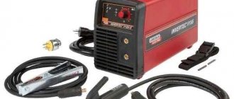
PSO 500 welding converter device
To power the electric arc with direct current, mobile and stationary welding converters are produced.
In Fig. Figure 17 shows the device of the single-station welding converter PSO-500, mass-produced by our industry. The single-station welding converter PSO-500 consists of two machines: a drive electric motor 2 and a DC welding generator GSO-500, located in a common housing 1. The generator armature 5 and the motor rotor are located on a common shaft, the bearings of which are installed in the covers of the converter housing. There is a fan 3 on the shaft between the electric motor and the generator, designed to cool the unit during operation. The generator armature is made of thin plates of electrical steel up to 1 mm thick and is equipped with longitudinal grooves in which insulated turns of the armature winding are laid. The ends of the armature winding are soldered to the corresponding plates of the collector 6. On the poles of the magnets there are mounted coils 4 with windings made of insulated wire, which are included in the electrical circuit of the generator. The generator operates on the principle of electromagnetic induction. When the armature 5 rotates, its winding crosses the magnetic field lines of the magnets, as a result of which an alternating electric current is induced in the armature windings, which is converted into a direct current using the collector 6; from the brushes of the current collector 7 when there is a load in the welding circuit, the current flows from the commutator to the terminals 9. The control and control equipment of the converter is mounted on the housing / in a common box 12. The converter is turned on by a packet switch 11. The magnitude of the excitation current and the operating mode of the welding generator are smoothly regulated by a rheostat in the circuit independent excitation by handwheel 8. Using a jumper connecting the additional terminal to one of the positive terminals from the series winding, you can set the welding current to 300 and 500 A. Operating the generator at currents exceeding the upper limits (300 and 500 A) is not recommended, since how the machine can overheat and disrupt the switching system. The magnitude of the welding current is determined by ammeter 10, the shunt of which is connected to the armature circuit of the generator mounted inside the converter housing. The windings of the GSO-500 generator are made of copper or aluminum. Aluminum busbars are reinforced with copper plates. To protect against radio interference that occurs during generator operation, a capacitive filter consisting of two capacitors is used. Before putting the converter into operation, it is necessary to check the case grounding; condition of the commutator brushes; reliability of contacts in internal and external circuits; turn the rheostat steering wheel counterclockwise until it stops; check that the ends of the welding wires do not touch each other; install a jumper on the terminal board according to the required welding current (300 or 500 A). The converter is started by connecting the motor to the network (batch switch). After connecting to the network, it is necessary to check the direction of rotation of the generator (when viewed from the collector side, the rotor should rotate counterclockwise) and, if necessary, swap the wires at the point where they are connected to the power supply network. Safety rules for operating welding converters.
When operating welding converters, you must remember: the voltage at the motor terminals, equal to 380/220 V, is dangerous, so they must be closed. All connections on the high voltage side (380/220 V) must only be carried out by an electrician authorized to carry out electrical installation work; the converter housing must be reliably grounded; the voltage at the generator terminals, equal to a load of 40 V, during idling of the GSO-500 generator can increase to 85 V. In the presence of high humidity, dust, high ambient air temperature (above 30ºC), a conductive floor or when working on metal structures, the voltage is higher 12V is considered dangerous to life. Under all unfavorable conditions (damp room, conductive floor, etc.), it is necessary to use rubber mats, as well as rubber shoes and gloves. The danger of damage to the eyes, hands and face from the rays of an electric arc, splashes of molten metal and the protective measures against them are the same as when working with welding transformers.
Pereosnastka.ru
The design of some welding converters
Category:
Metal welding
The design of some welding converters
Converter PSO-500. Designed for single-station manual welding and cutting, as well as mechanized submerged arc welding. The converter consists of a DC welding generator and a three-phase asynchronous electric motor. Normal operation of the converter is possible only in the direction of rotation indicated by the arrow on the generator panel.
The generator operates according to an independent excitation circuit with a series demagnetizing winding. It has four main magnetic poles. On two poles there are coils of an independent excitation winding (power winding), made of a large number of turns of thin wire. On the other two main poles there are coils of a series excitation winding (demagnetizing), made of a small number of turns of thick wire (bus). To ensure normal switching, the generator has two additional magnetic poles.
The box mounted on the converter housing contains a power supply unit for an independent excitation winding, an adjusting rheostat, an ammeter, and a package switch for starting and stopping the converter electric motor. The power supply unit for the independent excitation winding consists of a single-phase step-down transformer 220/80 V and a selenium rectifier connected in a single-phase bridge (full-wave) circuit.
The converter has two ranges of welding current - up to 300 A, up to 500 A. The output terminal board has four clamps. Welding wires are connected to the minus (-) and plus (+) terminals. The positive terminal is connected by a jumper to the 300 A terminal or to the 500 A terminal - this gives two current ranges. Smooth adjustment of the current in both limits is carried out by an adjusting rheostat.
The welding converter PD-501 has a similar device.
The PSO-500, PD-501 converters should not be confused with the PSG-500 converter, designed for mechanized welding with a consumable electrode in a carbon dioxide environment. All these converters are made in the same basic housing and are similar in appearance to each other. The PSG-500 converter has a rigid external characteristic, so it is impossible to use it for manual welding with coated electrodes. It is very easy to distinguish converters by the output terminal board. The PSG-500 converter has only two output terminals: negative (—) and positive (+).
Converter PSO-300. Designed for single-station manual welding and cutting. Normal operation of the converter is possible only in the direction of rotation indicated by the arrow on the generator panel.
The converter generator operates according to a parallel excitation circuit with a series demagnetizing winding. It has four main magnetic poles. On two poles there are coils of a parallel excitation winding (magnetizing), made of a large number of turns of thin wire. On the other two main poles there are coils of a series excitation winding (demagnetizing), made of a small number of turns of thick wire (bus). To ensure normal switching, the generator has two additional magnetic poles.
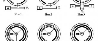
Rice. 1. Board of output terminals of tag generator PSO-500
The box mounted on the converter housing contains an adjusting rheostat, an ammeter, and a package switch for starting and stopping the converter electric motor.
The converter has two ranges of welding current - up to 180 A, up to 300 A. The clamp board has four clamps. Stepwise and smooth adjustment of the tsk is carried out similarly to the PSO-500 converter.
Converter 11D-305. Designed for single-station manual welding and cutting. Normal operation of the converter is possible only in the direction of rotation indicated on the end of the converter. The converter consists of a DC valve generator, a three-phase asynchronous electric motor, and control equipment.
The valve generator is a high-frequency inductor generator with a built-in rectifier unit. The power three-phase armature winding is located in the slots of the stator of the inductor generator. The excitation winding is attached to the generator housing and is placed between two gear packs of the generator rotor (inductor). The generator rectifier unit is assembled from silicon valves using a three-phase bridge circuit.
The control box of the converter contains ballast control equipment: a switch for starting and stopping the electric motor, a switch for welding current ranges, a power supply unit for the generator excitation winding (voltage transformer, current transformer, rectifier).
The converter has two ranges of welding current - up to 150 A, up to 350 A, which are provided by switching the three-phase winding of the generator armature. Smooth adjustment of the current within the ranges is carried out remotely using an adjusting rheostat connected to the control box.
Converter PSM-1000-4. Designed for simultaneous power supply of several manual welding stations, which are connected to the converter in parallel through ballast rheostats. Normal operation of the converter is possible only in the direction of rotation indicated on the generator panel.
The converter generator operates according to a mixed excitation circuit. It has four main magnetic poles. Coils of parallel and series excitation windings are located on all poles. Parallel winding coils have a large number of turns of thin wire, series winding coils have a small number of turns of thick wire (busbar). To ensure normal switching, the generator has four additional poles.
To smoothly regulate the generator voltage, a control rheostat is used, which is connected to the parallel excitation winding circuit of the generator.
The welding current at each welding station is adjusted in stages using a ballast rheostat. All stages of the rheostat can be connected to each other in parallel using switches. With an increase in the number of switched stages, the total resistance of the ballast rheostat decreases, and the welding current increases, and vice versa.
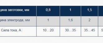
Ballast rheostat. It is an adjustable ohmic resistance consisting of several stages. In the welding circuit, the ballast rheostat is connected in series with the arc in the cut of the wire going to the electrode. Each stage of the ballast rheostat is connected to the welding circuit using a switch located on the front wall of the rheostat. Here on the plate is the approximate value of the welding current depending on the number of switched on stages.
The elements of the rheostat resistance stages are made of heat-resistant fechral wire of rectangular or round cross-section and are made in the form of a spiral.
Ballast rheostats are produced for rated currents of 200, 315, 500 A. Some brands of ballast rheostats: RB-200, RB-201, RB-300, RB-301, RB-302, RB-500, RB-501. The schematic diagram of the ballast rheostat is shown in Fig. 31.
If a current value greater than that for which the rheostat is designed is required, then two ballast rheostats can be connected in parallel.
Converter PSU-500. The design is similar to the PSO-500 converter. Is universal. Designed for single-station manual welding and cutting, for mechanized submerged arc welding, for mechanized welding in a carbon dioxide environment.
The converter generator has both falling and hard external characteristics. The generator is excited independently with a series demagnetizing winding.
The generator has four main magnetic poles and two additional ones. On the two main poles there are coils of an independent (magnetizing) excitation winding, made of a large number of turns of thin wire. The series (demagnetizing) field winding coils are located on the other two main poles.
To obtain a falling external characteristic of the converter, independent (magnetizing) and series (demagnetizing) excitation windings are used, as well as part of the winding turns of the additional poles of the generator.
To obtain a rigid external characteristic of the converter, part of the turns of the series (demagnetizing) field winding is turned off, but the full number of turns of the additional pole winding is turned on.
Switching of external characteristics is carried out by a packet switch and connecting the welding cables to two corresponding clamps on the terminal board.
Read more:
Welding units
Related articles:
pereosnastka.ru
What is a welding converter: its structure and purpose
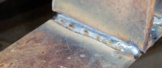
A welding converter is considered a type of operating current source, combining an electric motor, a generator and a rectifier in one housing. This installation is used during construction and installation work, when the electrical network sags and other welding machines operate unstably. Welding with a converter is carried out with a current of 500 amperes; you can weld thick workpieces and form a welding seam from 10 to 30 mm deep. The converter changes the voltage and type of current characteristics.
Advantages
Like any other equipment, welding converters (which historically appeared much earlier than inverters) have certain advantages, and at the same time they carry a number of certain inconveniences. Their advantages include:
- high welding current - for some models, in particular PSO-500 and PSG-500, it reaches 500 A, there are also more powerful devices;
- unpretentiousness at work;
- insensitivity to input voltage changes;
- relatively high reliability with qualified maintenance;
- good maintainability, ease of service.
The current that these devices are capable of delivering can weld very thick seams, about 10-30 mm. This is another important advantage due to which welding converters are used.
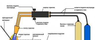
Principle of operation
The structure of all types of welding converters is typical:
- the current supplied to the asynchronous electric motor, after turning on the installation, is converted into mechanical current, which is supplied to the generator shaft;
- the generator produces the required frequency of current parameters, the method of electromagnetic induction is used in the work, an armature with windings is mounted on the shaft;
- The collector acts as a rectifier and supplies power to the output terminals.
A welding converter is essentially a combination of an electric motor operating from a 220 or 380 V network and a DC generator. The reliability of the converter is reduced by rotating components; energy losses in the process of converting electric current are high.
The equipment is valued for its stable current characteristics, regardless of surges in the voltage supplied to the motor. The regulator of performance characteristics is a rheostat; changing the number of turns of the independent winding changes the amperage. The output current is manually adjusted using an ammeter.
Safety precautions
Rules have been developed for working with generating electrical equipment. Before turning on, it is important to observe several points:
- Check the chassis grounding system, this is especially important for mobile installations; after transportation, you need to make sure that the grounding is reliable.
- The commutator brushes should be fine. To check, the rheostat steering wheel is moved to its extreme position, all the way (the direction of the steering wheel coincides with the movement of the windings - only counterclockwise).
- The next stage is to set the current parameters; control the position of the jumper.
- Connection to the network is carried out by a licensed electrician. It clamps the terminals on the electric motor in accordance with the safety rules of the PEU.
Operational requirements limit the current characteristics:
- permissible operating load 40 V;
- open circuit voltage is not higher than 85 V;
- when working in rooms with increased gas pollution, humidity, and dust, the permissible voltage is reduced to 12 V.
Special protective equipment is required: dielectric rubber mats, gloves. Welders need special clothing that protects the eyes, face, skin of the hands and feet from the effects of the welding electric arc and molten metal.
Source
What is the difference between a welding converter and a generator?
Generating installations are similar in the principle of generating operating current for welding. The generator runs on liquid fuel; the engine is petrol or diesel. The fuel operating principle is necessary for field conditions, when you have to cook away from power lines. Thermal energy is transformed into electrical energy without converting to mechanical energy.
The welding converter is equipped only with an electric motor connected to a single-phase or three-phase network. The installation is more complex than a generator; the motor and current generator are connected indirectly - by a shaft that transmits mechanical energy obtained from electrical energy.
general information
A welding inverter is a type of welding equipment that consists of two components: an electric motor and a welding generator. A typical representative is the PSO 500 welding converter.
The design of the welding converter is very simple. As we mentioned above, the main components are a generator and an electric motor. The electric motor runs on alternating current, and the generator runs on direct current. The operating principle is to convert alternating current from the engine into direct current by mechanically rotating the generator shaft. The shaft rotates manually, but thanks to the process of converting electrical energy.
Device
You can examine the equipment design in detail using the example of a stationary welding converter PSO 500, which produces two operating modes with maximum current characteristics of 300 or 500 amperes. Between the electric motor rotor and the generator armature, located on the same shaft, there is a fan with an impeller, which provides targeted cooling of the contact zone, where there is a high friction force. The bearings are located in the converter housing; it must be grounded.
The coil armature of the generator with 4 independent windings is connected to the collector, the rectifier plates are connected to the ends of the armature windings. When the coils rotate between the poles of the magnets, electromagnetic induction occurs and alternating current is induced. For winding, annealed copper or aluminum wire is used - metals with good electrical conductivity. To protect against external electromagnetic fields and vortex fields that arise during the operation of the converter, a “filter” is provided - an electrical capacitance (two capacitors that stabilize the voltage).
Classification
Manufacturers produce converters of various modifications. When choosing generating installations, the type of welding and the intended place of work are taken into account. Classification of current sources for welding work is carried out according to several criteria:
- Number of welding stations. Single-station ones are designed for connection to one device, for the work of one welder. Multi-station welders can supply power to several welders and perform work simultaneously in several work areas.
- Structurally, they differ in size and type of execution. There are:
mobile welding installations, equipped with wheels or stand carts;
stationary, attached to the foundation or installed directly at the welder’s workplace.
- Depending on the number of bodies, welding installations can be single or double.
- By type of current indicators:
with a falling current-voltage characteristic (single-body models PSO/single-station/ and PSM/multi-station/ with asynchronous three-phase motors) are intended for manual electric arc welding with a consumable or non-consumable electrode using protective fluxes or gases;
with rigid or flat-falling current-voltage characteristics are necessary for argon, semi-automatic, automatic welding (model range of current sources of the PSG type);
universal, operating in various modes (PSU installations with adjustable current-voltage characteristics).
The functionality of generating installations depends on the current-voltage characteristics. It is important to take this into account when choosing equipment.
armature with split poles, magnetization and demagnetization windings are mounted separately;
Separate demagnetization windings induce current from independent excitation.
The physical electromagnetic features of the equipment do not significantly affect the efficiency.