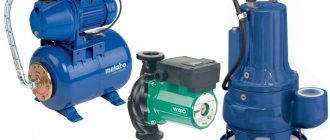
In systems with pumping equipment, various types of devices with microswitches and sensors are often used. They help to automatically start and turn off equipment without constantly monitoring the condition inside the water supply or in the tank as a whole. Let's consider one of such devices - a flow sensor. Let's get acquainted with the types of relays and their operating principles. Read to the end, and you will learn about the features of connecting and setting up the classic model.
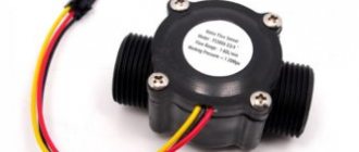
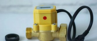
Example of a water flow switch Source prom.st
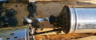
Flow sensor malfunctions
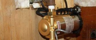
Design and principle of operation of a rotary pump
Common malfunctions that may occur during operation:
- The DHW mode does not start, the equipment is unstable. To make sure that it is the regulator that has failed, you need to take a multimeter and measure the resistance. If it is approximately 2.5 kOhm, then according to the table this indicator should be achieved when heated to 60 degrees. But if the device is cold, then the problem is definitely in the water flow sensor. The regulator will “say” that the water is already heated and additional temperature is not needed. To fix the problem, you will have to completely replace the failed sensor. But we must not forget that it has direct contact with water and before removal it is necessary to drain all the water from the boiler (Baksi or other companies) and shut off its supply.
- If error No. 201 appears on the indicator, this means that there is a break or damage to the wires that are connected to the regulator. For the regulator to work normally, you need to restore its original position.
- Error No. 202 - short circuit. In this case, you need to check the device itself or the wires that are connected to it.
Step-by-step instructions for adjusting the pressure switch
Step 1. Check the compressed air pressure in the accumulator. There is a rubber plug on the back of the tank, you need to remove it and get to the nipple. Check the pressure with an ordinary air pressure gauge; it should be equal to one atmosphere. If there is no pressure, pump up the air, measure the data and check the indicators after a while. If they decrease, there is a problem; we need to look for the cause and eliminate it. The fact is that most equipment manufacturers sell hydraulic accumulators with inflated air. If it is not there when purchasing, then this indicates a defect; it is better not to purchase such a pump.
First you need to measure the pressure in the accumulator
Step 2: Turn off the electrical power and remove the pressure regulator housing protective cover. It is fixed with a screw and removed using an ordinary screwdriver. Under the cover there is a contact group and two springs, compressed by 8 mm nuts.
To adjust the relay, you must remove the housing cover
Big spring. Responsible for the pressure at which the pump turns on. If the spring is fully tightened, the engine switching contacts will be permanently closed, the pump will turn on at zero pressure and run continuously.
Small spring. Responsible for turning off the pump; depending on the degree of compression, the water pressure changes and reaches the maximum value
Please note, not the optimal operating one, but the maximum according to the technical characteristics of the unit.
Factory relay settings need adjustment
For example, you have a delta of 2 atm. If in this case the pump turns on at a pressure of 1 atm, then it will turn off at 3 atm. If it turns on at 1.5 atm, then it turns off, respectively, at 3.5 atm. and so on. The difference between the switch-on and switch-off pressure of the electric motor will always be 2 atm. This parameter can be changed by changing the compression ratio of the small spring. Remember these dependencies, they are needed to understand the pressure regulation algorithm. The factory settings are set to turn on the pump at 1.5 atm. and shutdown at 2.5 atm., delta is 1 atm.
Step 3. Check the actual pump operating parameters. Open the water drain valve and slowly release the pressure, constantly monitoring the movement of the pressure gauge needle. Remember or write down at what indicators the pump turned on.
When the water drains, the arrow indicates a decrease in pressure
Step 4. Continue monitoring until it turns off. Also record the values at which the electric motor shuts down. Find out the delta, subtract the smaller value from the larger value. This parameter is needed so that you can navigate at what pressures the pump will turn off if you adjust the compression force of a large spring.
Now you need to notice the values at which the pump turns off
Step 5: Turn off the pump and loosen the small spring nut about two turns. Turn on the pump, record the moment it turns off. Now the delta should decrease by about 0.5 atm, the pump will turn off when the pressure reaches 2.0 atm.
Use a wrench to loosen the small spring a couple of turns.
Step 6. You need to ensure that the water pressure is in the range of 1.2–1.7 atm. As mentioned above, this is the optimal mode. Delta 0.5 atm. already installed by you, you need to lower the inclusion threshold. To do this, you need to release the large spring. For the first time, turn the nut, check the starting period, and if necessary, fine-tune the compression force of the large spring.
Adjusting the large spring
You will have to start the pump several times until you get it to turn on at 1.2 atm and turn off at a pressure of 1.7 atm. All that remains is to replace the housing cover and turn on the pumping station. If the pressure is correctly adjusted, the filters are always in good condition, then the pump will operate for a long period of time, there is no need to do any special technical maintenance.
Criteria for selecting a relay for a pump
What is and why do you need a water flow switch?
Generator voltage regulator relay: diagram, principle of operation
In household water supply systems, the action of a pumping station without water quite often occurs and threatens an accident. This problem is called “dry running”.
As a rule, the liquid cools and lubricates the elements of the system, thereby ensuring its normal operation. Even short-term dry operation leads to deformation of individual parts, overheating and failure of the equipment motor. Negative consequences apply to both surface and deep-well pump models.
Dry running occurs for various reasons:
- incorrect choice of pump capacity;
- unsuccessful installation;
- violation of the integrity of the water pipe;
- low fluid pressure and lack of control over its level, for which a pressure switch is used;
- accumulated debris in the pumping pipe.
An automatic sensor is necessary in order to completely protect the device from the threats posed by a lack of water. It measures, controls and maintains constant water flow parameters.
Pumping equipment equipped with a sensor has many advantages. It lasts longer, breaks down less often, and uses energy more economically. There are also relay models for boilers
Purpose and benefits
When operating domestic water supply systems, there are often situations when the pump turns on when there is no liquid in the pipes. Such situations, if they occur frequently and continue for a long time, cause overheating of the pump motor and deformation of its parts, which ultimately leads to failure of the entire device. The water pumped by pumping equipment simultaneously performs lubricating and cooling functions, so “dry running,” as it is also called, negatively affects the technical condition of both circulation and submersible pumps.
In order to prevent the occurrence of the described situations, they use a water flow sensor for the pump, operating in automatic mode. Sensors that monitor water flow are successfully used to control the operation of pumping stations serving hot and cold water supply systems, as well as heating systems.
Sensor location diagram in the water supply system
The automatic device in question monitors the parameters of the flow of water that passes through it, and in cases where they differ from the standard ones, it automatically turns on or off the pumping equipment. Working on this principle, the sensor not only protects pumping equipment from “dry running”, but also ensures constant water flow parameters.
Among the advantages of operating pumping equipment on which a fluid flow sensor is installed are:
- reducing energy consumption and, accordingly, reducing the cost of paying for it;
- minimizing the risk of failure of pumping equipment;
- increasing the service life of pumping equipment.
Where are they used?
Screw pump: principle of operation, scope and design features
Flow sensors are used in devices where control of the water supply system to an apartment or private house is necessary. By installing this type of equipment on a gas boiler, you can significantly reduce your monthly payment, and the heat generator will also become much safer to use.
For gas boilers
There is a water flow regulator in all boilers (Buderus and other models). Thanks to the device, the heat generator can work as a device for heating a home and heating water.
The gas boiler water pressure sensor is mounted on the pipeline. Once installed, it begins to respond to flow as soon as the hot tap is opened.
The regulator transmits a signal to a special board installed inside the boiler. After this, the circulation pump automatically starts and the pressure in the gas injectors decreases. As a result, the water circulation valve closes. After this, the water heating nozzles turn on, and the liquid begins to warm up in the heat exchanger. After closing the valve, the mounted sensor for the gas boiler records this action and transmits the corresponding signal to the board.
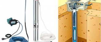
For pumps
In many private houses, an autonomous water supply system is installed. This is necessary if there is often low pressure on the site and the owner wants his yard to be independent of the centralized water supply. The equipment is installed so that the water pressure in the house always remains at a high level.
The system includes:
- special pump;
- a tank where water is poured;
- control system.
You can connect various household appliances to the pump, for example, dishwashers or washing machines. In this case, the regulator is necessary for timely activation of the pump, ensuring a stable water supply.
And it doesn’t matter whether the wash has started, the tap is open in the kitchen, or water is draining from the toilet tank - the regulator performs the same functions for any type of household equipment connected to the system.
Also, the owners of the living space in question often connect the sensor in question to automatic watering in the country or in a private house. Here the device not only performs the opening function, it regulates the amount of water that should be consumed at a time.
This function is very useful if dosed watering is used so as not to over-moisten the soil. For stable operation, the flow regulator is mounted to the central pipeline, and it transmits all information to the system control panel.
Review of popular models
There are two types of pressure switches: mechanical and electronic, the latter are much more expensive and are rarely used. The market offers a wide range of devices from domestic and foreign manufacturers, making it easier to select the required model.
RDM-5 Gilex (15 USD) is the most popular high-quality model from a domestic manufacturer.
Characteristics
- range: 1.0 - 4.6 atm.;
- minimum difference: 1 atm.;
- operating current: maximum 10 A;
- protection class: IP 44;
- factory settings: 1.4 atm. and 2.8 atm.
Genebre 3781 1/4″ (10 cu) is a budget model made in Spain.
Characteristics
- body material: plastic;
- pressure: upper 10 atm;
- connection: threaded 1.4 inches;
- weight: 0.4 kg.
Italtecnica PM/5-3W (13 cu) is an inexpensive device from an Italian manufacturer with a built-in pressure gauge.
Characteristics
- maximum current: 12A;
- working pressure: maximum 5 atm;
- lower: adjustment range 1 - 2.5 atm.;
- upper: range 1.8 - 4.5 atm.
The pressure switch is the most important element in the water intake system, providing automatic individual water supply to the house. It is located next to the hydraulic accumulator, the operating mode is set using adjusting screws inside the housing.
When organizing an autonomous water supply in a private house, pumping equipment is used to lift water. In order for the water supply to be stable, it is necessary to select it correctly, since each type has its own technical characteristics and features.
For efficient and trouble-free operation of the pump and the entire water supply system, it is necessary to purchase and install an automation kit for the pump, taking into account the characteristics of the well or well, the water level and its expected flow.
A vibration pump is chosen when the amount of water spent per day does not exceed 1 cubic meter. It is inexpensive, does not create problems during operation and maintenance, and its repair is simple. But if water is consumed from 1 to 4 cubic meters or water is located at a distance of 50 m, it is better to purchase a centrifugal model.
Typically the kit includes:
- an operating relay, which is responsible for supplying and blocking voltage to the pump when the system is emptying or filling; The device can be immediately configured at the factory; self-tuning for specific conditions is also allowed:
- a collector that supplies and distributes water to all points of consumption;
- pressure gauge for measuring pressure.
Manufacturers offer ready-made pumping stations adapted to specific requirements, but a self-assembled system will work most efficiently. The system is also equipped with a sensor that blocks its operation during dry running: it disconnects the engine from power.
Sensors for protection against overload and integrity of the main pipeline, as well as a power regulator, ensure safe operation of the equipment.
Sensor types
Today, the most popular and advanced water flow devices are reed switch relays and Hall sensors.
Description:
- A flow meter or Hall sensor is a small turbine with a magnet. As soon as the turbine begins to rotate, the magnet creates a field and generates electrical pulses that are transmitted to the boiler board (for example, Ferroli).
- The reed switch regulator also uses magnetism. A float magnet is installed inside the chamber. As soon as the water pressure increases, the float moves and begins to act on the reed switch (several magnetic plates that move apart under the influence of the float).
Design and principle of operation
The operating principle of the flow switch is based on the mechanical effect of the water flow in the pipeline on the sensor that controls the electronic circuit for turning on and off the electric pump. Relays have different operating principles and, depending on the design of the sensor, are divided into several types.
Petal relays
One of the most common types, the main elements are a petal sensor with a magnet located in the water flow and a reed switch placed in the device body and securely insulated.
As water flows through the pipeline, the vertically located petal sensor rotates along its axis and deviates from the vertical position, bringing the built-in magnet closer to the reed switch. Its contacts inside the cylinder are closed and the pump is connected to a source of electricity through a triac (double symmetrical thyristor).
If there is no water in the pipeline, the petal returns to its original position, moving the magnet away from the reed switch and thereby opening its contacts.
This leads to the cessation of supply voltage to the pump through the semistor, as a result of which it turns off.
Operating principle
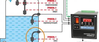
There are several types of water flow switches and similar safety devices, each of which is equipped with different automation that turns the pump on and off in response to certain indicators.
Most common triggers:
- Liquid level (water level switch);
- Liquid pressure level at the outlet pipe (press control);
- Presence of water flow (flow switch);
- Temperature of the working environment (thermal relay.
Let's look at each of these devices in more detail.
Classic relay
A classic example of a relay that controls the flow of liquid
Such a device consists of two main structural elements: a reed switch and a petal (valve) on which a magnet is mounted. The reed switch, which acts as a contact that responds to changes in the position of the magnet, is located outside the water flow and is reliably insulated.
On the opposite part of the structure there is a second magnet, which creates a reverse force, which is necessary to return the petal to its original position at the moment the fluid flow weakens.
When the pump is filled with water, it acts on the petal, causing it to rotate around its axis. The movement of the petal brings the magnet closer to the reed microswitch, which is activated by the resulting magnetic field.
Connecting and adjusting the sensor
The efficiency of the sensor that monitors the flow of water and controls the operation of pumping equipment largely depends on the correct installation of this device. It should be borne in mind that such a sensor, regardless of the type and purpose of the pipeline, can only be installed in horizontal sections. In this case, it is necessary to ensure that the sensor membrane is located strictly in a vertical position.
When installing a liquid flow sensor, it is connected to the drain part of the pipeline using a threaded coupling. In this case, the distance at which such a device should be located from the pipe itself cannot be less than 55 mm.
Flow sensor installation diagram
On the housing of factory water flow sensors there is always an arrow that indicates in which direction the liquid should move through them. When installing the sensor on the pipeline, you must ensure that this arrow coincides with the direction of water movement. If the sensor is installed in a system through which heavily contaminated liquid is transported, filters must be placed in front of it for the correct operation of such a device.
Electrical connection diagram
Despite the fact that fluid flow sensors are supplied from manufacturing plants with already adjusted parameters, independent adjustment must be performed periodically. For this purpose, special bolts are provided in the design of the sensors. With the help of the latter, the degree of compression of the springs is increased or decreased, setting the level of pressure at which this device will operate.
Leaf type flow sensor adjustment controls
So, to adjust the water flow sensor with your own hands, you need to perform the following steps:
- drain the water from the pipeline system and make sure that the pressure has reached zero;
- turn on the pump and start filling the system with water;
- when the pump is turned off, which occurs due to a signal from the sensor, record the value of the liquid pressure;
- Draining the liquid from the system again, record the pressure value of its flow at which the pump will turn on;
- by removing the sensor cover and using a special bolt, adjust the degree of compression of the large-diameter spring (this way you will set the minimum pressure level at which the device will operate and the pump will turn on; it should be borne in mind that compression of such a spring increases the pressure level, and weakening reduces it);
- Having filled the system again with water and starting to drain it, check whether the sensor is adjusted correctly and whether it turns off the pump at the required pressure level (if the device is adjusted incorrectly, the entire procedure described above should be repeated);
- by changing the degree of compression of a spring of small diameter, set the maximum pressure level at which the pump will turn off (the difference between the sensor response thresholds increases when such a spring is compressed and decreases when it is weakened);
- after adjusting the degree of compression of a small-diameter spring, check that this procedure is performed correctly by starting to fill the system with water and recording the pressure value at which the pump turns off (if this adjustment is performed incorrectly, it should also be repeated until the desired result is achieved).
Device selection criteria
When choosing equipment that controls the force of water flow, you should carefully study its technical characteristics.
Particular attention should be paid to the operating temperature and pressure range for which it is designed, the diameter of the threads and mounting holes, the protection class, and application nuances. It is also important to clarify what materials the product is made from.
Experts consider devices made of brass, stainless steel, and aluminum to be the most reliable and durable. These materials protect the structure from the critical consequences of a common phenomenon in water supply systems - water hammer.
When considering different modifications of the relay, it makes sense to purchase a version made of metal. The housing and working components of such devices are highly durable.
This fact allows the equipment to withstand serious loads for a long time that arise due to significant pressure in the water supply from the liquid passing through the sensor.
The pressure value at which the relay operates must correspond to the power of the installed pump. The parameters of the water flow circulating through the pipeline depend on this characteristic.
It is advisable to choose a device with two springs that controls the operation of the pumping station according to certain lower and upper pressure marks.
The operating temperature range of the sensor directly indicates its possible area of application. For example, models with a high limit temperature are designed for hot water supply circuits and heating systems. For cold water pipelines, a range of up to 60 degrees is sufficient
Another important criterion that deserves special mention is the climatic conditions necessary for the operation of the product. This refers to the recommended air temperature and humidity level that the device needs to provide in order for it to perform at its best.
The maximum permissible load for a particular device is determined by the protection class specified in the technical specifications.
When purchasing a flow sensor, you should check the thread diameter and the dimensions of the mounting holes in the equipment: they must fit perfectly with the pipeline elements. The correctness and accuracy of further installation, as well as the efficiency of the relay after installation, depend on this.
Design features
The main tasks that water flow control sensors installed in domestic pipelines solve are to turn off pumping equipment at a time when there is no liquid in the system or its flow pressure exceeds the standard value, and turn it on again when the pressure drops. An effective solution to these important problems is provided by the sensor design, which consists of the following elements:
- a pipe through which water enters the sensor;
- a membrane that makes up one of the walls of the inner chamber of the sensor;
- a reed switch that provides closing and opening of the pump power supply circuit;
- two springs of different diameters (the degree of their compression regulates the pressure of the fluid flow, at which the water flow switch for the pump will operate).
Main components of an industrial flow sensor
The device of the above-described design works as follows:
- Entering the inner chamber of the sensor, the water flow puts pressure on the membrane, displacing it.
- The magnetic element fixed on the back side of the membrane, when it is displaced, approaches the reed switch, which leads to the closure of its contacts and the pump being turned on.
- If the pressure of the water flow passing through the sensor drops, the membrane returns to its original position, the magnet moves away from the switch, its contacts open, and accordingly, the pumping unit is turned off.
The operating principle of a flow sensor based on a permanent magnet and a reed switch
Sensors that monitor water flow are installed quite simply in pipeline systems for various purposes.
The main thing is to choose the right device, paying attention to its operating parameters and characteristics of the pumping equipment
Main characteristics
When choosing water flow sensors to equip a pipeline system, the following parameters must be taken into account:
- material for manufacturing the body and internal elements;
- operating pressure for which the sensor is designed;
- temperature range of the liquid to control the flow of which the device will be used;
- protection class and requirements for operating conditions;
- diameter of mounting holes and thread parameters in them.
Each of the above parameters affects the operational features of water flow sensors, so it is worth considering them in more detail.
The reliability of such a device, its ability to withstand loads arising during operation, as well as its durability depend on the material from which the sensor body and its internal parts are made. When choosing a fluid flow sensor, it is better to give preference to models for the manufacture of which various metals were used - stainless steel, brass or aluminum. During operation, both the body of the flow sensor and its internal elements experience significant pressure from the liquid passing through it. Only durable materials can withstand such a load for a long time. In addition, phenomena such as water hammer are common in pipelines, the consequences of which can quickly damage the sensor if inappropriate materials were used for its manufacture.
Flow sensor with brass body
The operating pressure at which the fluid flow sensor can operate correlates with the power of the pump used, so special attention should be paid to this parameter. In addition, this parameter also determines what characteristics the liquid flow transported through the pipeline will have. Those models of water flow sensors, which are designed with two springs, can control the operation of the pump at the lower and upper pressure levels. It is better to give preference to devices of this particular type.
The temperature of the liquid for which the sensor is designed has a direct impact on the systems in which it can be used. Naturally, when choosing such a sensor to equip a heating or hot water supply system, you should pay attention only to those models that can work with water heated to a high temperature. For pipelines through which cold water is transported, flow sensors are used, designed to work with liquids having a temperature of 60–80°.
Boost pump with flow sensor
The level of humidity and ambient temperature at which the fluid flow sensor can be operated are also important parameters. The protection class of such a device indicates what loads it can withstand when working in tandem with pumping equipment.
Sensors that monitor water flow are usually chosen for ready-made pipeline systems or for those whose design has already been developed. That is why you should pay attention to the dimensions of the mounting holes: they must fully correspond to the dimensions of the pipeline elements on which the sensor is planned to be installed.
Device connection diagram
The operating efficiency of the relay greatly depends on its correct installation. It must be remembered that the device can only be installed on those sections of the pipeline that are located horizontally. In this case, you will need to ensure that the sensor membrane is in a vertical position. The correct relay connection diagram looks like this:
During installation, the sensor must be connected to the drain part of the pipe using a threaded connection. The distance at which the relay should be located from the pipe should be more than 5.5 cm.
There is an arrow on the body of the device indicating the direction of liquid circulation. When installing the device, you need to make sure that this arrow coincides with the direction of water flow in the system. If dirty water is used for domestic purposes, then cleaning filters should be installed in front of the sensor.
Step-by-step instructions on how to connect
A detailed installation diagram for the pressure sensor is in the instructions with which the device is sold. In general, the sequence of steps is the same.
Connection to frequency converter
The sensor is connected to the inverter in the following order:
- mount the sensor on the pipeline, connect the device to the high-frequency converter with a signal cable;
- in accordance with the diagram given in the documentation, connect the wires to the appropriate terminals;
- configure the software part of the converter and check the operation of the connection.
To prevent interference and ensure proper operation of the inverter, a shielded signal cable is used for installation.
To the water supply system
A typical sensor for installation on a pipeline requires a fitting with five terminals:
- water inlet and outlet;
- exit to expansion tank;
- under the pressure switch, usually with external thread;
- branch for pressure gauge.
A cord from the pump is connected to the sensor to control turning it on or off. The power supply is provided by a cable that is laid to the panel.
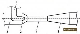
Rotary relays and flow type sensors
Rotary sensors are mainly used to measure and control fluid flow. Structurally, they are made in the form of a paddle wheel rotating in a fluid flow; its rotation speed is recorded by sensors. The electronic circuit allows for analog, frequency or discrete control of the operation of the equipment.
Piston devices
The piston is placed in the valve seat and, under the influence of water pressure, moves in the vertical direction to a height proportional to the force of the flow. A permanent magnet mounted on the piston approaches the reed switch and the contacts in it close. Piston devices can be installed on horizontal and vertical pipelines thanks to the built-in return spring, which returns the piston to its original position in the absence of flow.
appearance
Construction of a double-circuit gas boiler
In order to understand the principle of operation of a gas double-circuit boiler, it is necessary to understand its structure. It consists of many individual modules that heat the coolant in the heating circuit and switch to the DHW circuit. The coordinated work of all components allows you to count on trouble-free operation of the equipment. Knowing the structure of a double-circuit boiler, you can understand its operating principle.
We will not consider the design of double-circuit boilers with precision down to the screw, since it is enough for us to understand the purpose of the main components. Inside the boiler we will find:
Design of models with two circuits: heating and DHW circuit.
- The burner, located in an open or closed combustion chamber, is the heart of any heating boiler. It heats the coolant and generates heat for the operation of the DHW circuit. To ensure accurate support of the set temperature, it is equipped with an electronic flame modulation system;
- Combustion chamber - the above burner is located in it. It can be open or closed. In a closed combustion chamber (or rather, above it) we will find a fan responsible for pumping air and removing combustion products. It is this that is the source of quiet noise when the boiler is turned on;
- Circulation pump – ensures forced circulation of coolant through the heating system and during operation of the DHW circuit. Unlike the combustion chamber fan, the pump is not a source of noise and operates as silently as possible;
- Three-way valve - this is the thing that is responsible for switching the system to hot water generation mode;
- The main heat exchanger - in a double-circuit wall-mounted gas boiler, it is located above the burner, in the combustion chamber. Here the coolant used in the heating circuit or in the DHW circuit for heating water is heated;
- Secondary heat exchanger - this is where hot water is prepared;
- Automation - it controls the operating parameters of the equipment, checks the temperature of the coolant and hot water, controls modulation, turns on and off various components, monitors the presence of flame, records errors and performs other useful functions.
At the bottom of the buildings there are pipes for connecting the heating system, cold water pipes, hot water pipes and gas pipes.
Some models of gas double-circuit boilers use dual heat exchangers. But the operating principle remains almost the same.
You may notice that the design of the geyser differs only in the absence of a heating circuit.
We found out the structure of a double-circuit wall-mounted gas boiler - it seems a little complicated, but if you understand the purpose of certain components, the difficulties will disappear. Here we can note the similarity with a gas instantaneous water heater, from which a burner with a heat exchanger remains here. Everything else is taken from wall-mounted single-circuit boilers. An undoubted advantage is the presence of a built-in piping - this is an expansion tank, a circulation pump and a safety group.
When analyzing the operating principle and design of a gas double-circuit boiler, it should be noted that water from the DHW circuit is never mixed with the coolant. The coolant is poured into the heating system through a separate pipe connected to the heating. Hot water is prepared using part of the coolant circulating through the secondary heat exchanger. However, we will talk about this a little later.
Installation of a relay on a pump or station
If installation of the device is required, the work can be done independently, especially if you have to be away and there is no way to constantly monitor the operation of the pumping equipment.
When you do not need to install a relay:
- if water is pumped from a well with a large volume, that is, liquid reserves are not limited, and the pump power is minimal;
- It is possible to turn off the installation when the water level drops.
Equipment installation rules:
It is important to monitor the membrane - the part must take a vertical position. Installation is carried out to the drain pipeline section using threaded couplings. There is a special slot for this. Before starting work, the threads are sealed with linen or other plumbing thread
Winding the thread towards the end clockwise will increase the reliability of fastening and fixation. Factory sensors are equipped with an arrow drawn on the body - this is the direction of flow, which must match during installation. When installing relays in water supply pipelines with dirt particles, cleaning filters are first installed. It is better to mount them next to the sensor to extend the service life of the device.
Testing of the installed device is carried out with connection to the power supply:
- the free ends of the contacts are connected to the wire core;
- grounding is mounted to the screw;
- the device is connected by connecting the device with a wire (watch the color of the corresponding wires);
- system functionality is checked.
Self-adjustment of the water movement sensor
The factory device is equipped with bolts, by tightening or loosening which you can increase/decrease the spring compression. Bolts will be required if you need to install the sensor at a certain pressure level at which the mechanism is triggered.
Algorithm of actions:
- drain the liquid from the system;
- wait until the pressure mark reaches zero;
- start the pumping unit;
- run the water back in the slowest mode;
- remember the flow pressure indicator when the pump relay is turned off;
- drain the liquid again, recording the indicators when the system starts operating.
Now you need to open the relay, use the bolt to adjust the compression level of the larger spring - this will trigger the device when the pump starts. The adjustment is made taking into account that strong compression will increase the degree of pressure, and weak compression will decrease it. Then the compression force of the smaller spring is adjusted - here the limit of the maximum pressure level is set, upon reaching which the relay will automatically turn off the pump.
As soon as the adjustment is completed, start the system, evaluate the results of the work when filling the pipeline and draining the flow. If adjustment changes are necessary, repeat the procedure. Checking functionality and adjusting operating parameters is an annual procedure that extends the life of the device.
Self-adjustment procedure
For adjustment, the sensor has special bolts. By loosening or tightening them, you can reduce or increase the compression force of the spring.
This sets the pressure level at which the device will operate.
Almost always, manufacturing companies produce equipment with adjusted settings. Despite this, sometimes additional self-adjustment is required
In most cases, setting up automatic equipment is not difficult.
It is advisable to adhere to the following algorithm:
- drain the liquid from the system until the pressure mark reaches zero;
- turn on the pumping unit and slowly let the water back in;
- record the flow pressure indicator when the pump is turned off with a sensor;
- start draining again and remember the indicators at which the pumping equipment will start working;
- open the relay and use the adjusting bolt to set the minimum level of compression of the larger spring required to activate the device and start the pump (more compression increases the degree of pressure, less - reduces it);
- in a similar way, adjust the compression force of a smaller spring mechanism, setting the limits of the maximum pressure, upon reaching which the relay measuring the water flow will turn off the pump.
Having completed all the described manipulations, you should make sure that the adjustments made are correct. To do this, the pipeline is filled with liquid and then drained, assessing the sensor’s response when the set values are reached.
If the test result is unsatisfactory, the procedure is repeated.
Having insufficient experience and qualifications, it is better to seek help in adjustment from specialists. They will analyze the specific situation, take into account the technical characteristics of the equipment and select the most correct pressure level values
To ensure that the pipeline through which the liquid passes works properly and stably, regular annual checks of the flow sensors are carried out. If necessary, the operating parameters are adjusted.
Review of famous manufacturers and prices
Several models in the $30-40 price category are considered the most famous and reliable:
- Genyo Lowara Genyo 8A. Manufacturer – Poland. The main direction of the company is the production of electronic equipment for control systems. The relay is designed for use in domestic water supply systems and is characterized by high quality and long service life. By monitoring the flow pressure in the pipes, the sensor starts the pumping system at a water flow rate of 1.6 l/minute. The unit requires an electrical connection and consumes 2.4 kW/hour. Operating temperature +5..+60 C.
- Grundfos UPA 120. Manufacturer's plants are located in Romania and China. The device has small dimensions, is convenient to install and is indicated for individual water supply systems. That is, it can be used both in private buildings and apartments. The device starts up at a liquid flow rate of 1.5 l/minute, completely preventing the functionality of the system at idle. The extreme operating temperature is +60 C.
The models have been tested and adapted to domestic operating conditions. Numerous reviews characterize metering sensors as durable and practical units at an affordable price.
Types of dry running sensors
Expensive modifications of pumping units are already equipped with built-in dry-running protection sensors. For example, all Grundfos brand pumps, as well as some models from the manufacturer Sterwin, Watt, Whirlwind and Wilo, are also equipped with such devices.
When operating budget devices, the sensors must be independently connected to a submersible pump. Let us dwell in more detail on the various types of these devices and the principles of their operation.
There are three categories of dry running sensors:
- protection relay;
- level sensors;
- water flow and pressure sensors.
Protection relay
It is an electromechanical device that controls the pressure of water flowing through the pump unit. When the pressure decreases, the power circuit opens.
The pump dry-running protection relay consists of a membrane, a contact group and several wires. The membrane controls the fluid pressure. In working condition it is open. When the pressure drops to 0.1-0.6 atmospheres, the membrane compresses the relay contacts and the pump turns off. A drop in pressure to this value indicates the occurrence of the following violations:
- the fluid pressure has dropped to a minimum level due to the exhaustion of the source;
- pump filter clogged;
- the pump is above the water level, so the pressure has dropped to zero.
The protection relay can be built into the device body or mounted on the surface as a separate part.
If the water supply structure contains a hydraulic accumulator, then the protective mechanism is installed together with a pressure switch, in front of the hydraulic accumulator.
Water level sensors
This type of equipment is used to determine the actual liquid level in a well or well. Two types of sensors can be used:
- Float switch. The connection diagram for the dry run analyzer must be assembled in such a way that its contacts are included in the power supply circuit of the pump motor. The float is located afloat. When the level of the working medium decreases, the float changes its position, its contacts open, and the pump turns off. This is the simplest method of protection, which is durable and easy to operate.
Advice! In order for the float to operate in a timely manner, you need to configure it successfully
It is important that when the sensor is triggered, the pump housing is still immersed in the liquid medium
2.Water level control sensor. This is a relay that consists of two separate devices lowered to different depth levels. One device is dipped to the lowest possible level of pump operation. The second sensor is located slightly lower. When both devices are located directly under water, a small current flows between them. If the level of the working medium decreases to a minimum value, the current stops flowing and the sensor is triggered, opening the power circuit.
3. Sensors that monitor the liquid level make it possible to turn off the pumping equipment before the body of the device reaches the surface of the water surface. This means that the equipment is thoroughly protected from damage.
Water flow and pressure sensors
There are two types of water flow sensors for the pump, which monitor the passage of the working fluid through the pump and ensure its protection against dry running. These are flow switches and flow controllers.
- The flow switch is an electromechanical type product. There are turbine and petal ones. The principle of their functioning also differs:
- The rotor of turbine relays contains an electromagnet that generates an electromagnetic field when fluid passes through the turbine. Specialized sensors read the electrical impulses generated by the turbine. When the pulses disappear, the sensor turns off the pumping device from the electrical supply;
- the petal devices contain a flexible plate. If water does not penetrate the pump, the plate moves away from its original location, causing the mechanical contacts of the relay to open. In this case, the power supply to the pumping device is interrupted. This option is characterized by simplicity of design and affordable price.
These block modules turn off the pump if there is no water flow and turn on the device if the pressure in the system drops below a preset level.
2. Flow controllers (automation unit, press control). These are electronic products that simultaneously monitor several important flow characteristics. They check the pressure, signal when water suction has stopped, and automatically turn pumping equipment on and off. Many mechanisms are equipped with check valves. High reliability justifies the high cost.
How to set pressure using a flow switch
Briefly - for 5 seconds. – press button “1”:
In this case, the “accident” lamp should blink red. This is where we entered programming mode. Now we turn on the pump, and as it works, it builds up pressure. It is clear that all taps in the house must be closed. We look at the pressure on the pressure gauge. For example, we need the water supply to be 2 atm, so we wait for the pump to build up this pressure. As the arrow on the pressure gauge shows the required pressure, press button “1” again. The pump will turn off.
We press the “2” button, thereby “driving” into the relay’s memory that at this pressure the pump should turn off.
Now we are programming the lower limit. To do this, open any tap so that the pressure begins to drop. When the pressure gauge shows the lower pressure we need, press button “1” again and the pump will turn on. By pressing button “2” we “drive” the relay into the head so that at this pressure the pump must be turned on.
Practical examples of relay configuration
Let's look at cases when turning to adjusting the pressure switch is really necessary. This usually happens when purchasing a new device or when frequent pump shutdowns occur. You will also need to configure it if you received a used device with lost parameters.
Connecting a new device
At this stage, you should check whether the factory settings are correct and, if necessary, make some changes to the operation of the pump.
Image gallery Photo from Turn off the power, completely empty the system of water until the pressure gauge reaches o. Turn on the pump and monitor the readings. We remember at what value it turned off. Then we drain the water and remember the parameters at which the pump starts working again
We twist the large spring to increase the lower limit. We check: we flush the water and remember the on and off values. The second parameter should increase along with the first. We adjust until we achieve the desired result
We perform the same actions, but with a small spring. You need to act carefully, since the slightest change in the position of the spring responds to the operation of the pump. Having slightly tightened or loosened the nut, we immediately check the result of the work
Having completed all manipulations with the springs, we take the final readings and compare them with the initial ones. We also look at what has changed in the operation of the station. If the tank began to be filled to a different volume, and the on/off intervals changed, the setup was successful
Stage 1 – equipment preparation
Stage 2 - adjusting the switching value
Stage 3 - adjusting the shutdown value
Stage 4 – testing the system operation
To track the progress of work, it is recommended to write down all received data on a piece of paper. In the future, you can return the initial settings or change the parameters again.
The pump stopped turning off
In this case, we forcibly turn off the pumping equipment and proceed in the following order:
- We turn it on and wait until the pressure reaches its maximum level - let's say 3.7 atm.
- We turn off the equipment and lower the pressure by draining water - for example, to 3.1 atm.
- Lightly tighten the nut on the small spring, increasing the differential value.
- We check how the cut-off pressure has changed and test the system.
- We configure the optimal option by tightening and loosening the nuts on both springs.
If the reason was due to incorrect initial settings, it can be solved without buying a new relay. It is recommended to regularly, once every 1-2 months, check the operation of the pressure switch and, if necessary, adjust the on/off limits.
Situations that do not require adjustment
There can be many reasons when the pump does not turn off or turn on - from a blockage in the communications to engine failure. Therefore, before you start disassembling the relay, you should make sure that the rest of the pumping station equipment is working properly.
If everything is fine with the other devices, the problem is in the automation. Let's move on to inspecting the pressure switch. We disconnect it from the fitting and wires, remove the cover and check two critical points: the thin pipe connecting to the system and the contact block.
Image gallery Photo from To check whether the hole is clean, it is necessary to dismantle the device for inspection, and if a blockage is detected, clean it
The quality of tap water is not ideal, so the problem is often solved by simply cleaning the inlet to remove rust and mineral deposits.
Even devices with a high degree of moisture protection may experience failures due to oxidized or burnt wire contacts.
To clean the contacts, use a special chemical solution or the simplest option - the finest sandpaper
You need to act very carefully
The connection pipe to the hydraulic tank is clogged
Cleaning the relay inlet
Electrical contacts are clogged
Cleaning the contact block. If cleaning measures did not help, and adjusting the position of the springs was also in vain, most likely the relay is not subject to further use and should be replaced with a new one
If cleaning measures did not help, and adjusting the position of the springs was also in vain, most likely the relay is no longer suitable for further use and should be replaced with a new one.
Suppose you come across an old but working device. Its adjustment occurs in the same order as setting up a new relay. Before starting work, make sure that the device is intact, disassemble it and check that all contacts and springs are in place.
Installation features
Paddle switches are mounted either at the pump inlet or at the valve inlet. Their task is to record the initial entry of liquid into the working chamber, and therefore contact with it must be detected first of all on the relay itself.
Pressure control units are installed only with the help of specialists, as they require adjustment. They are installed in the same way as the petals, by connecting the inlet to the pumping device. However, unlike conventional petals, pressure switches are almost always used in conjunction with pumping stations.
Thermal relays are rarely used separately, since the thing is too expensive. It will most likely be connected at the assembly stage of the pump itself. However, a good master will certainly be able to cope with the installation of this device. The complexity of the installation lies in the need to mount several sensitive thermal sensors, and then bring them together.
DIY water leakage sensor: 3 schemes of varying complexity
Water is life. If it is in the tap, or in the heating radiator, this is good. And if it is on the floor of your apartment, or on the ceiling of your neighbor below, this is a big financial and moral problem.
Of course, it is necessary to regularly check the water supply and heating system for corrosion or cracks in plastic pipes. However, a water breakthrough usually occurs suddenly, without any sign of impending danger. It’s good if at this moment you are at home and not sleeping.
But, according to the law of meanness, leaks occur at night, or when you are not at home.
Simple rules for dealing with this problem (especially for old housing stock, with worn-out networks):
- Regularly inspect water pipes and heating system elements for defects, spot rust, tight connections, etc.
- When leaving home, close the entrance valve on the riser.
- Outside the heating season, close the taps on the radiators (if any).
- Use a leakage protection system.
We will consider the last item on the list in more detail.
How to signal a water leak
The solution to the problem came into everyday life from the yachting world. Since the ship's lower tier rooms (especially holds) are located below the waterline, water regularly accumulates in them. The consequences are clear, the question is how to deal with it. It is irrational to assign a separate sailor on watch for control. Then who will give the command to turn on the sump pump?
There are effective tandems: a water presence sensor and an automatic pump. As soon as the sensor detects that the hold is full, the pump motor turns on and pumping occurs.
The water sensor is nothing more than a regular float on a hinge connected to the pump switch. When the water level rises by 1–2 cm, the alarm and the sump pump motor are triggered at the same time.
Comfortable? Yes. Safely? Of course. However, such a system is unlikely to be suitable for a residential building.
- Firstly, if the water reaches a level of 1–2 cm over the entire area of the room, it will run through the threshold of the front door onto the landing (not to mention the neighbors below).
- Secondly, a bilge pump is completely unnecessary, since the cause of the breakthrough must be immediately found and localized.
- Thirdly, the float system for rooms with a flat floor is ineffective (unlike watercraft with a keeled bottom). By the time the “required” level for operation is reached, the house will fall apart from dampness.
Therefore, a more sensitive alarm system against leaks is needed. This is a question of sensors, and the executive part comes in two types:
1. Alarm only. It can be light, sound, or even connected to a GSM network. In this case, you will receive a signal on your mobile phone and will be able to remotely call an emergency team.
2. Turning off the water supply (unfortunately, this design does not work with the heating system, only water supply). After the main valve, which supplies water from the riser to the apartment (it does not matter whether it is before or after the meter), an electromagnetic valve is installed. When a signal is sent from the sensor, the water is shut off and further flooding is stopped.
Naturally, the water shut-off system also signals a problem in any of the above ways. These devices are offered in a wide range by plumbing stores.
It would seem that material damage from a flood is potentially higher than the price of peace of mind. However, the majority of citizens live by the principle “until thunder strikes, a man will not cross himself.”
And more progressive (and prudent) homeowners make a water leakage sensor with their own hands.
Operating principle of leakage sensors
Speaking about the block diagram, everything is very simple. A certain element fixes the liquid at the point of its placement and sends a signal to the executive module. Which, depending on the settings, can give light or sound signals, and (or) give a command to close the valve.
How the sensors work
We will not consider the float mechanism, since it is not effective at home. Everything is simple there: the base is fixed to the floor, a float is suspended on a hinge, which, when floating, closes the switch contacts. A similar principle (mechanical only) is used in the toilet cistern.
The most commonly used sensor is a contact sensor, which uses the natural ability of water to conduct electrical current.
Of course, this is not a full-fledged switch through which 220 volts passes. To two contact plates (see
illustration) a sensitive circuit is connected, which detects even a small current. The sensor can be separate (as in the photo above), or built into a common housing.
This solution is used on mobile autonomous sensors powered by a battery or accumulator.
If you do not have a smart home system, and water is supplied without any solenoid valves, a simple sensor with an audible alarm can be used as a starting option.
Homemade sensor of the simplest design
Despite its primitiveness, the sensor is quite effective. Home craftsmen are attracted by this model due to the cheap cost of radio components and the ability to assemble it literally “on the knee”.
The base element (VT1) is an NPN transistor of the BC515 series (517, 618 and the like). It supplies power to the buzzer (B1).
This is the simplest ready-made buzzer with a built-in generator, which can be purchased for pennies, or removed from some old electrical appliance. The power required is about 9 volts (specifically for this circuit).
There are options for 3 or 12 volt batteries. In our case, we use a Krona type battery.
How the scheme works
The secret is in the sensitivity of the collector-base transition. As soon as a minimum current begins to flow through it, the emitter opens and power is supplied to the sound element. A squeak is heard. An LED can be connected in parallel, adding visual signaling.
The signal to open the collector junction is given by the very water whose presence needs to be signaled. Electrodes are made from metal that is not subject to corrosion. These could be two pieces of copper wire, which can simply be tinned. Connection points on the diagram: (Electrodes).
You can assemble such a sensor on a breadboard.
Then the device is placed in a plastic box (or a soap dish), with holes made in the bottom. It is advisable that if water gets in, it does not touch the circuit board. If you want aesthetics, the printed circuit board can be etched.
The disadvantage of such a sensor is different sensitivity to different types of water. For example, distillate from a leaking air conditioner may go unnoticed.
Based on the concept: an inexpensive autonomous device, it cannot be integrated into a single security system for your home, even a homemade one.
A more complex circuit, with a sensitivity regulator
The cost of such a scheme is also minimal. Performed on the KT972A transistor.
The operating principle is similar to the previous version, with one difference. The generated signal about the presence of a leak (after opening the emitter junction of the transistor), instead of a signaling device (LED or sound element), is sent to the relay winding.
Any low-current device, such as RES 60, will do. The main thing is that the supply voltage of the circuit matches the characteristics of the relay.
And from its contacts, information can be sent to the actuator: smart home system, alarm system, GSM transmitter (to a mobile phone), emergency solenoid valve.
An additional advantage of this design is the ability to adjust sensitivity. Using a variable resistor, the collector-base transition current is regulated. You can adjust the response threshold from the appearance of dew or condensation to the full immersion of the sensor (contact plate) in water.
Leak sensor on LM7555 chip
This radio element is an analogue of the LM555 microcircuit, only with lower energy consumption parameters. Information about the presence of moisture comes from the contact pad, indicated in the illustration as a “sensor”:
To increase the response threshold, it is better to make it in the form of a separate plate connected to the main circuit with wires with minimal resistance.
The best option in the photo:
If you don’t want to spend money on buying such a “limit switch,” you can etch it yourself. Just be sure to cover the contact paths with tin to increase corrosion resistance.
As soon as water appears between the tracks, the plate becomes a closed conductor. An electric current begins to flow through the comparator built into the chip. The voltage quickly increases to the operating threshold, and the transistor (which acts as a key) opens. The right side of the diagram is the command-executive one. Depending on the execution, the following happens:
- Top diagram. The signal on the so-called “buzer” (beeper) is triggered, and the optionally connected LED lights up. There is another use case: several sensors are combined into a single parallel circuit with a common sound alarm, and the LEDs remain on each block. When the sound signal is triggered, you will accurately determine (by the emergency light) which unit has triggered.
- Bottom diagram. The signal from the sensor is sent to an emergency solenoid valve located on the water supply riser. In this case, the water is shut off automatically, localizing the problem. If you are not at home at the time of the accident, the flood will not happen, and material losses will be minimal.
Information: Of course, you can also make a shut-off valve with your own hands. However, it is better to purchase this complex device ready-made.
The circuit can be made using a printed circuit board layout that is equally suitable for both LM7555 and LM555. The device is powered by 5 volts.
Important! The power supply must be galvanically isolated from 220 volts so that dangerous voltage does not enter a puddle of water during a leak.
In fact, the ideal option is to use a charger from an old mobile phone.
The cost of such a homemade product does not exceed 50–100 rubles (for the purchase of parts). If you have old components in stock, you can reduce costs to zero.
The body is at your discretion. With such a compact size, finding a suitable box will not be difficult. The main thing is that the distance from the common board to the contact plate of the sensor is no more than 1 meter.
General principles for placing leakage sensors
Any owner of a premises (residential or office) knows where the water supply or heating communications are located. There are not many potential leak points:
- shut-off taps, mixers;
- couplings, tees (this is especially true for propylene pipes that are connected by soldering);
- inlet pipes and flanges of a toilet tank, washing machine or dishwasher, flexible hoses of kitchen faucets;
- connection points for metering devices (water meters);
- heating radiators (can leak both over the entire surface and at the junction with the main line).
Of course, ideally, the sensors should be located precisely under these devices. But then there may be too many of them, even for the DIY option.
In fact, 1-2 sensors per potentially dangerous room are enough. If it is a bathroom or toilet, as a rule, there is an entrance door threshold. In this case, water is collected as if in a pan; the layer can reach 1–2 cm until the liquid spills through the threshold. In this case, the installation location is not critical, the main thing is that the sensor does not interfere with moving around the room.
In the kitchen, sensors are installed on the floor under the sink, behind the washing machine or dishwasher. If a leak occurs, it will first form a puddle in which the alarm will sound.
In other rooms, the device is installed under heating radiators, since water supply pipes are not laid through the bedroom or living room.
It would not be superfluous to install the sensor in a niche through which risers of pipelines and sewers pass.
The most critical points of water breakthrough
With uniform operating pressure, the risk of leakage is minimal. The same applies to mixers and taps, if you open (close) the water smoothly. The weak point of the pipeline system manifests itself during water hammer:
- when closed, the water supply valve to the washing machine creates a pressure that is 2–3 times higher than the nominal value of the water supply system;
- the same, but to a lesser extent, applies to the locking fittings of the toilet cistern;
- Heating radiators (as well as their connection points to the system) often do not withstand the pressure testing carried out by heating supply companies.
How to properly place sensors
The contact plate should be located as close to the floor surface as possible without touching it. Optimal distance: 2–3 mm. If the contacts are placed directly on the floor, constant false alarms will occur due to condensation. Long distance reduces the effectiveness of protection. 20–30 millimeters of water is already a problem. The sooner the sensor works, the less losses.
reference Information
Regardless of whether the leakage protection system is purchased in a store or made by yourself, you need to know the uniform standards for its operation.
Device classification
- By the number of secondary protective devices at the facility (emergency shut-off valves with electromagnetic drive). Leakage sensors should not shut off all water supplies if shut-off systems are distributed among consumers. Only the line on which a leak is detected is localized.
- According to the method of submitting information about a water supply (heating system) accident. Local alarm assumes that people are present at the site. Remotely transmitted information is organized taking into account the prompt arrival of the owner or repair team. Otherwise, it is useless.
- Notification method: local sound or light alarm (on each sensor), or output of information to a single remote control.
- Protection against false positives. Typically, finely tuned sensors perform more efficiently.
- Mechanical or electrical protection. An example of mechanics is the Aqua Stop system on the supply hoses of washing machines. There is no alarm on such devices, the scope of application is limited. Self-production is impossible.
Conclusion
By spending a little time and a minimum of money, you can protect yourself from serious financial problems associated with a flood in your apartment.
on this topic
Types of water flow switch
The most common water flow switch configuration for a pump is a petal switch. The classic circuit of the device consists of the following elements:
- inlet pipe;
- valve (petal) located on the wall of the inner chamber;
- isolated switch;
- springs of a certain diameter.
The reed switch opens and closes the power supply circuits that activate the compression spring. The principle of operation of the sensor in a water flow: when the chamber is filled with liquid, the flow forcefully displaces the valve from its axis, affecting the magnet, which operates the switch. The contacts close and the pump turns on.
There are several types of sensors with their own operating characteristics and application possibilities.
Mechanical paddles
The device is a device equipped with a blade that is built into the pipeline. The principle of operation is standard: when a flow enters, the blade deflects and acts on a magnet. The contacts close, the switch sensor is activated. The simplicity of the unit explains the wide range of applications. In addition, such sensors are practically not subject to wear and do not require maintenance - there is nothing to break in them.
Mechanical piston
The device operates on the basis of a magnetic piston system. Operating principle: when a flow enters, the piston with a magnet rises, closing the contacts - the relay is triggered to start. Without flow, the piston drops to its original position, preventing dry running. The main advantage of the device is the variety of designs that allow the device to be mounted in any position. Mechanical piston relays are used in high pressure systems.
Thermal
The device is equipped with a meter for the level of thermal energy dissipation from the built-in heating element. Depending on the change in the heating rate of the liquid, the flow itself and its flow rate are recorded. The thermal sensor is used only for safe types of liquid. Due to the use of the hot-wire principle, it is prohibited to use the relay to measure flammable substances, as well as liquids that change composition when heated.
Ultrasonic
The universal pulse water flow sensor operates on the principle of the acoustic effect. The device transmits an ultrasonic pulse through the flow, determining the liquid level. The most common are products whose functionality uses the movement of vibrations of a moving fluid. The devices are suitable for any substances, including flammable ones, and are easy to install and maintain.
Allowable relay failures
There are several distinctive failures for pressure switches. In many cases, they are simply replaced with new devices. But there are small problems that can be removed personally without the help of a professional.
If the pressure switch was found to be the source of the malfunction, the professional will insist on replacing the device. All service activities for cleaning and replacing contacts cost the client more than purchasing and installing a new device
The most common failure is characterized by air leakage from the relay.
when the receiver is turned on. In this case, the culprit may be the start valve. You just need to replace the gasket and the problem will be fixed.
Frequent activation of the air blower indicates loosening and displacement of the pressure bolts. Here you will need to double-check the threshold for turning the relay on and off and adjust them in accordance with the instructions in the previous section.