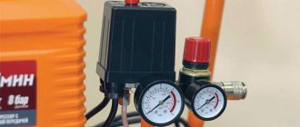
For the uninterrupted operation of an independent water supply, automation devices are required. One of them is considered to be a water pressure switch for the pump. This device is a safety device and controls the operation of the water pump. When the pressure in the pipeline decreases, the switching element turns on the pumping unit, and when it increases, it turns it off. Fluid pressure thresholds can be adjusted.
Purpose
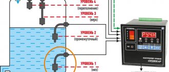
The water pressure switch is designed to control the amount of liquid in the system. For this, a system with a pump and a hydraulic accumulator is used, which can be supplemented with a water presence sensor.
Rice. 1. Purpose of the water pressure switch
The pump in the water supply system can continuously supply water pressure to the main line, filling the expansion tank. The more liquid accumulates in the container, the higher the pressure. Due to the fact that the amount of accumulated water in the expansion tank is periodically consumed according to domestic needs, the need to restart the compressor unit is tied to the pressure in the system. Therefore, the main purpose of the water pressure switch is to supply and turn off power to the pump, depending on the achievement of the limit values of the measured parameter.
The measurement process will differ depending on the design features of the specific relay type. To understand the principle of operation, let us consider in more detail the design of the most common type of logical element for household pumps.
Models on the market
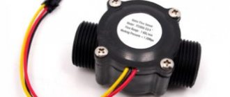
Arduino pressure sensors are divided according to application environments and design features directly related to the end result. There are models protected from moisture and intended for use in liquids, others work only as atmospheric aneroids, others are installed in a flow gap, and others are used as determinants of internal pressure of gas filling a container. They are all united by the presence of common interfaces for connecting to the microcontroller and low, no more than a few milliwatts (less often Watts), energy consumption.
| Name | Power (V) | Accuracy | Resolution (hPa) | Range (hPa) | Operating Temperature (°C) | Interfaces | Note | ||
| SPI | I2C | UEXT | |||||||
| Atmospheric | |||||||||
| MOD-BMP085 | 1.8–3.6 | 0.03 hPa | 0.01 | 300–1100 (from 500 m below sea level to 9 km altitude | –40..+85 | + | + | Temperature measurement | |
| GY-BMP280 | 3.3 | 0.12 hPa | 0.0016 | 300–1100 | –40..+85 | + | + | Temperature measurement up to +65, with an accuracy of 0.01 | |
| MD-PS002 | 5V | ±0.2% | –100–+150 | –40..+125 | + | Only non-aggressive environments | |||
| Liquid | |||||||||
| MS5803-02BA | 1.8–3.6 | 20 cm liquid | 30–1100 (10–2000) | –40..+85 | + | + | |||
| MS5803-07BA | 1.8–3.6 | 0–7 mbar (70 m immersion) | –20..+85 | + | + | ||||
| Open-Smart 5V G1/4 0-1.2 MPa Hydraulic Pressure Sensor for Non-Corrosive Water | 5 | 1.5 % | 1–2.4 mbar (max 3) | 0..+85 | Own connector connected to I2C via a resistor, the sensor is equipped with a thermometer | ||||
Of course, not all existing models are included in the above list. It lists only those that have a certain popularity and are requested by users.
Device
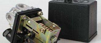
Structurally, the water pressure switch can be electronic or mechanical. The first option is more compact and all processes in it are carried out using an electronic circuit. The second type of equipment is more widely used in everyday life due to its simplicity and accessibility. As a rule, mechanical models are not much inferior to electronic ones when installed in a home water supply system, so we will consider just this option as an example.
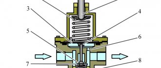
The entire device consists of three component blocks - hydraulic, mechanical and electronic, as shown in the figure below:
Rice. 2. Water pressure switch device
All blocks are reported into a single system, where changes in the parameters of the measured medium are displayed on each of them. However, it is more convenient to consider the design separately for each block.
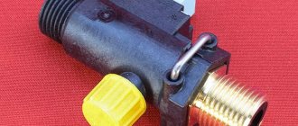
The hydraulic unit is represented by a movable sensing element fixed in the flange and bellows. In accordance with clause 4.1. GOST R 55023-2012 such an element can be a membrane, piston or other movable device.
Rice. 3. Components of the electrical and mechanical unit of the water pressure switch
The electronic and mechanical unit are represented by the following components:
- Terminals for connecting the cores of the supply wires - in this case there are two groups of terminals, one of which allows you to secure the phase, neutral and protective conductors from the distribution network. The second group of terminals is used for the outgoing power supply line to the pump.
- Couplings - used to enter the cable into the pressure switch. One of the couplings is designed to enter the cable from the distribution network, and the second is to supply power to the pump.
- Contact group - driven by the mechanical force of levers and a spring mechanism. It turns on and off depending on the state of the sensitive element.
- Spring drive - responds to physical deformation of the sensing element. As a result of reaching the threshold value, it moves the rod, which switches the contacts.
- Regulators - in most models, they allow you to adjust the maximum and minimum shutdown limits. Designed to adjust water pressure parameters in the circuit.
- Base – serves as a base for securing all relay elements. Depending on the model, it is made of metal or polymer. Provides strength and reliability of the structure.
The entire structure is placed in a protective housing, which prevents debris and moisture from entering the device. Depending on the climatic version, it has a different design and composition of components.
What does the sensor measure?
Pressure is a certain physical quantity numerically equal to the perpendicularly directed force acting per unit surface area. The sensor itself can be thought of as a kind of very sensitive scale. The last remark is made because both water and gases also have their own mass, which affects the surface beneath them. In practice, due to this factor, it is possible to determine the depth of immersion (the lower, the greater the weight of the water layer) or the height of ascent into the atmosphere (the higher, the lower the density, and therefore the weaker the impact). In addition, regarding air pressure, do not forget about weather fluctuations. A sharp drop in the named characteristic of the atmosphere means rain or storm.
Again, about gases and partially liquids. They can be compressed. But, compacted substances will tend to return to their original state. And the stronger the compression, the more powerful the final pressure of the gas or liquid inside the vessel containing them will be.
Actually, the Arduino detector in question measures the force of influence per unit area of the sensor element of the device. True, in most of the models produced, what is described is not all of their functionality. As a bonus, many measure the ambient temperature, and some also measure humidity or acceleration.
Principle of operation
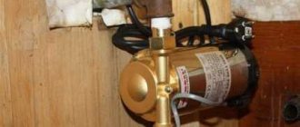
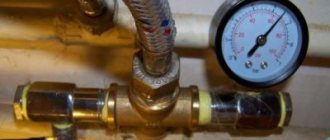
To consider the operation of the water pressure switch for the pump, let’s look at the diagram in which it performs its direct functions. If we consider the existing water supply system in a private house, its structure will look like this:
Rice. 4. Operating principle of the water pressure switch
As you can see in the figure above, a submersible pump, through a check valve and a water supply system, fills the accumulator and supplies water to the water supply system. The pump itself is supplied with power through a pressure switch connected to the open circuit. The sensitive element of the relay is discharged into the pipeline through a tee (in some situations, a five-terminal fitting can be used instead of a tee). The logic of work is organized as follows:
- When the pump is turned on in the network, the pressure in rubles is at zero. The relay membrane is at the minimum mark, so its contacts are closed. Through the contact group, voltage is supplied to the pump windings, and water enters the pipeline.
- As the water supply system and expansion tank fill, the water pressure increases proportionally. The membrane in the tee will gradually absorb increasing fluid pressure.
- When the accumulator is filled and the maximum pressure limit in the system is reached, the sensitive element of the relay is deformed under the influence of water. Due to which the rod will move through a spring-lever mechanism and shift the contact group to the opposite position. The power supply to the pump will stop, and the maximum pressure level will be established in the system.
- As soon as a tap or shower is opened in the house, water will begin to flow out of the system and the accumulator, as a result of which the pressure will begin to decrease linearly. As soon as the water level reaches a minimum point at which the pressure drops below the established limit, the membrane deforms again. As a result of deformation of the sensing element, the rod will move the contact group to the opposite position. The contacts again close the power supply circuit of the pump, which will begin pumping water into the system.
The cycle of switching contacts of the water pressure switch is repeated as the set pressure limits for the transported resource are reached. However, it should be noted that if there is no water in the well or if the pipe breaks, the pressure switch will not respond to the damage, and power will be continuously supplied to the pump. This situation can become an emergency, therefore, to prevent premature wear of the elements and failure of the pump, a dry-running relay is additionally installed.
Transition to a new pressure switch v2.0 – MicroPython based on ESP8266
And why couldn’t I sleep...
Everything would be fine... I would go to smoke the tandoor and fry pilaf, but no, my soul is eager to fight, and even with ESP8266 , and MicroPython “smeared”. And everything in the house is on them, controlled, and via the phone. It's nice how