Here you will learn:
- What is and why do you need a water flow switch?
- Design features
- Operating principle
- Device connection diagram
- Installation features
- Self-adjustment procedure
- How to set pressure using a flow switch
- Device selection criteria
- 3 best models of water flow switch for a pump
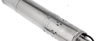
A water flow switch is a special device installed to protect water pumps from running dry. When water disappears in the system, the protective device is activated and turns off the water supply equipment.
What is and why do you need a water flow switch?
In household water supply systems, the action of a pumping station without water quite often occurs and threatens an accident. This problem is called “dry running”.
As a rule, the liquid cools and lubricates the elements of the system, thereby ensuring its normal operation. Even short-term dry operation leads to deformation of individual parts, overheating and failure of the equipment motor. Negative consequences apply to both surface and deep-well pump models.
Dry running occurs for various reasons:
- incorrect choice of pump capacity;
- unsuccessful installation;
- violation of the integrity of the water pipe;
- low fluid pressure and lack of control over its level, for which a pressure switch is used;
- accumulated debris in the pumping pipe.
An automatic sensor is necessary in order to completely protect the device from the threats posed by a lack of water. It measures, controls and maintains constant water flow parameters.
Pumping equipment equipped with a sensor has many advantages. It lasts longer, breaks down less often, and uses energy more economically. There are also relay models for boilers
The main purpose of the relay is to independently turn off the pumping station when the liquid flow is insufficient and turn it on after normalization of the indicators.
Design features
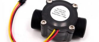
The main tasks that water flow control sensors installed in domestic pipelines solve are to turn off pumping equipment at a time when there is no liquid in the system or its flow pressure exceeds the standard value, and turn it on again when the pressure drops. An effective solution to these important problems is provided by the sensor design, which consists of the following elements:
- a pipe through which water enters the sensor;
- a membrane that makes up one of the walls of the inner chamber of the sensor;
- a reed switch that provides closing and opening of the pump power supply circuit;
- two springs of different diameters (the degree of their compression regulates the pressure of the fluid flow, at which the water flow switch for the pump will operate).
Main components of an industrial flow sensor
The device of the above-described design works as follows:
- Entering the inner chamber of the sensor, the water flow puts pressure on the membrane, displacing it.
- The magnetic element fixed on the back side of the membrane, when it is displaced, approaches the reed switch, which leads to the closure of its contacts and the pump being turned on.
- If the pressure of the water flow passing through the sensor drops, the membrane returns to its original position, the magnet moves away from the switch, its contacts open, and accordingly, the pumping unit is turned off.
The operating principle of a flow sensor based on a permanent magnet and a reed switch
Sensors that monitor water flow are installed quite simply in pipeline systems for various purposes. The main thing is to choose the right device, paying attention to its operating parameters and characteristics of the pumping equipment.
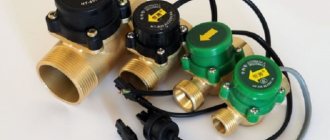
Popular models
A wide range is a blessing, but not always, because abundance can become “evil”, only making it difficult to choose. Therefore, we need to briefly talk about the models that are considered one of the most popular and in demand.
- Lowara Genyo 8A. This device is produced by the Polish company LOWARA, which produces devices “specializing” in equipment protection and pump control. This sensor is intended for installation in domestic conditions. Its operating temperature range is 5-60°, electricity consumption is 2.4 kW.
- WWQ-RD (RD-1, RD-2). This is a line of fairly high-quality, effective, but inexpensive devices. The devices protect against idle operation; the models are equipped with a built-in check valve.
- Water robot Turbi. This is a pump control unit from the Russian manufacturer UNIPUMP. The device is capable of working with any type of pumping equipment. Water temperature range - from 5 to 35°, power - up to 1.5 kW.
- Vortex - pump controller, or dry running sensor. This device also has a built-in check valve. The maximum water temperature is 55°, power is 1.2 kW.
Other companies producing popular water flow sensors: AquamotoR, Belamos, ELITECH, Eterna, Grundfos, PUMPMAN, Tim, UNIPUMP.
The water flow sensor controls and automates the operation of the main element of the autonomous system, so this element will not be superfluous in any case. On the contrary, its installation will extend the life of the pump, since the relay is an almost one hundred percent guarantee of the absence of all serious installation failures.
The protective relay is a kind of reinsurance, but the design will pay for itself in any case. Especially when you consider the cost of a failed pump. But the decision always remains with the owners. The following video will show you how to install a simple but necessary petal device:
Was this article helpful? We want to improve. Thanks for your opinion!
Operating principle
There are several types of water flow switches and similar safety devices, each of which is equipped with different automation that turns the pump on and off in response to certain indicators.
Most common triggers:
- Liquid level (water level switch);
- Liquid pressure level at the outlet pipe (press control);
- Presence of water flow (flow switch);
- Temperature of the working environment (thermal relay.
Let's look at each of these devices in more detail.
Classic relay
A classic example of a relay that controls the flow of liquid
Such a device consists of two main structural elements: a reed switch and a petal (valve) on which a magnet is mounted. The reed switch, which acts as a contact that responds to changes in the position of the magnet, is located outside the water flow and is reliably insulated.
On the opposite part of the structure there is a second magnet, which creates a reverse force, which is necessary to return the petal to its original position at the moment the fluid flow weakens.
When the pump is filled with water, it acts on the petal, causing it to rotate around its axis. The movement of the petal brings the magnet closer to the reed microswitch, which is activated by the resulting magnetic field.
The reed switch connects the contacts of the pump and the electrical network, as a result of which the device is turned on. As soon as the flow of liquid has stopped, the petal, which no longer receives additional pressure, returns to its original position under the influence of the force of an additional magnet and the contacts open.
Advantages of the petal flow switch:
- Does not reduce water supply pressure;
- Works instantly;
- No delay between retriggers;
- Using the most accurate circulation trigger to turn on the pump;
- Simplicity and unpretentiousness of design.
There are also flow switches, the valve design of which is made without return magnets, where the second magnet is replaced by conventional springs. However, such relays in practice show less stability, since they are overly susceptible to the influence of small pressure surges in the water flow.
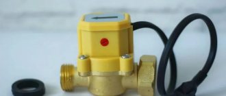
Press control
Press control relay for water flow
Press control gives a command to turn on the pump only when the water pressure level in it rises to a certain level (this indicator is adjustable, most often it ranges from 1 to 2 Bar), the pump is turned off due to opening of the contacts within 5-10 seconds after completely stopping the flow of water pumped out of the well.
Such devices can be used either in conjunction with a hydraulic accumulator, performing the function of controlling a pumping station, or installed directly on the outlet pipe of the pump, protecting it from idling.
Press control, in comparison with a conventional relay that responds to changes in the level of water flow, has one significant drawback - if it is installed on a surface-type pump, then each time before turning it on you must fill the unit with water yourself. The problem can be solved by installing additional check valves, but this is far from a panacea.
Thermal relay
Among all the above types of safety devices, the thermal relay has the most complex design. The technology of its operation is based on the thermodynamic principle, according to which the thermal difference between the temperature of the water flow in the pump and the temperature to which the relay sensors are set is compared.
When the thermal relay is connected to the pump, which is located inside the well, a certain amount of electricity is constantly supplied to it, which is spent on heating the sensors to a temperature several degrees higher than the temperature of the measured liquid.
In the presence of water flow, the sensors are cooled, which is fixed by a microswitch. The thermal change is a signal after which the connection between the pump contacts and the electrical network is made. As soon as the flow of water from the well stops, the microswitch disconnects the contacts and the pump turns off.
Thermal relay that responds to temperature changes
In addition to downhole units, a thermal flow relay is an ideal option for dry-running protection for a circulation pump.
The thermal relay allows you not only to increase the useful life of the circulation device, but also to save a considerable amount of electricity, since the thermal relay automatically turns off the pump when pressurizing the water flow in the heating line is not required.
When the heater is turned off and the water in the system is cold, the circulation pump is not needed, and the thermal relay keeps the contacts closed. When you turn on the boiler, as the water in the pipes reaches the set temperature, the thermal relay turns on the circulator, and it begins to build up pressure to the required level.
It is worth noting that most leading manufacturers of circulation pumps independently install thermal flow switches on their devices. This is mainly typical for premium class pumps. This is due to their high cost and complexity of design.
Level relay
The simplest and most utilitarian version of a safety device for a water pump is a water level switch, commonly known as a float switch.
The “float,” which must be mounted inside the source 20-25 centimeters above the level of the pump, monitors the amount of water in the source, and as soon as the water drops below the float sensor, the pump automatically turns off.
The relay itself is connected to the phase that is supplied to power the pump. The float sensor is adjusted by changing the length of the adjusting cable. Higher-quality floats can be customized with additional functions, but this already applies to expensive models of equipment, which are quite rare in domestic use.
A float switch is a proven means of protection for any well and drainage devices, but a water level switch cannot be used in deep wells, since there are serious difficulties with its precise adjustment.
Submersible Drain Pump with Float Switch
Also, floats do not always work well in cramped conditions, when the difference between the diameter of the well and the pump is only a few tens of millimeters. In this case, there is simply no point in using it, since the operation of the float will become too unstable.
Float switches are used both on conventional well pumps and on drainage samples. Moreover, there they are even more in demand, because unlike standard wells, the working environment of a drainage pump tends to constantly decrease. Dry running of drainage models is no less harmful than borehole or well pumps.
Setting the dry running protection relay
The device is designed in such a way that its setting provides for changes in the level of communication between the surface that reacts to the working pressure and the contact group that should be triggered. For these purposes, the relay has screws that either compress or relax the springs. On almost all models, the factory settings set the lower response limit to 1.4 atm, the upper limit to 2.8 atm. The user has the opportunity to choose his own indicators. To increase the lower response limit, rotate the adjusting screw from right to left, to lower it, vice versa.
It is important to understand that as the lower limit increases, a natural increase in the upper limit occurs (the difference of 1.4 atm remains). A prerequisite for setting up is to set the relay shutdown limit lower than the pump pressure. If this point is not taken into account, the pump will not respond to dry running at all, which will cause its rapid failure.
Setting the dry running protection relay
Another adjusting nut allows you to change the difference between the extreme limits of the device's response. As already mentioned, the factory setting is usually 1.4 atm. By tightening the nut, the difference can be increased up to 2 atm. In this case, the upper limit of the shutdown also changes, which also follows the same fate during configuration. It is very important that the level of the highest cut-off pressure does not exceed the value that the pump itself can produce. Reducing the lower level and the difference in boundaries occurs in direct opposition - by unscrewing the adjusting nuts.
You can also watch a video on how to configure the dry-running protection relay:
Cautions:
- If the minimum setting limit is set too low, it may happen that an error of 0.3 bar will not allow the relay to turn off the voltage in time.
- If the limit is too high, the same error can trigger the activation of dry-running protection, and the pump will be turned off for no reason.
- With a minimum dry running pressure, it will take longer to start the pump (you will have to drain the water from the accumulator).
- An error of 0.2-0.3 bar can provoke the so-called. “rollback” of pressure. As a result, with a large volume of consumption, a sharp drop in pressure of up to 0.4 bar can be observed. To avoid idle shutdowns, you need to lower the idle pressure level.
The massive transition to autonomous water supply involves the mandatory use of pumping units. For full and uninterrupted operation, they must be protected as much as possible from overheating. One effective way to achieve this is to use dry-running sensors, which allow you to instantly turn off equipment after a loss of water. To install a relay yourself, you need to understand the principles of its operation and know the connection diagram.
Dry running protection: selection, connection, configuration, principle of operation 4.71 (94.29%) 14 votes
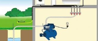
Device connection diagram
The operating efficiency of the relay greatly depends on its correct installation. It must be remembered that the device can only be installed on those sections of the pipeline that are located horizontally. In this case, you will need to ensure that the sensor membrane is in a vertical position. The correct relay connection diagram looks like this:
During installation, the sensor must be connected to the drain part of the pipe using a threaded connection. The distance at which the relay should be located from the pipe should be more than 5.5 cm.
There is an arrow on the body of the device indicating the direction of liquid circulation. When installing the device, you need to make sure that this arrow coincides with the direction of water flow in the system. If dirty water is used for domestic purposes, then cleaning filters should be installed in front of the sensor.
Scope of application of liquid flow switches
Liquid flow detectors are most widely used in automatic fire extinguishing systems, where they are part of the control component.
In addition, sensors are used in the following areas:
- oil and gas industry, to control the filling of gas and oil pipelines;
- metallurgical industry, for control of fluid supply in technological processes;
- chemical production, as a flow switch to control the movement of aggressive and dangerous liquid products;
- water supply for greenhouses and conservatories;
- automated feeding and water supply systems in agriculture;
- watering, irrigation and fertilizer supply systems;
- food industry;
- water supply and sanitation systems for residential premises;
- climate systems where control of water or refrigerant supply is necessary.
Installation features
Paddle switches are mounted either at the pump inlet or at the valve inlet. Their task is to record the initial entry of liquid into the working chamber, and therefore contact with it must be detected first of all on the relay itself.
Pressure control units are installed only with the help of specialists, as they require adjustment. They are installed in the same way as the petals, by connecting the inlet to the pumping device. However, unlike conventional petals, pressure switches are almost always used in conjunction with pumping stations.
Thermal relays are rarely used separately, since the thing is too expensive. It will most likely be connected at the assembly stage of the pump itself. However, a good master will certainly be able to cope with the installation of this device. The complexity of the installation lies in the need to mount several sensitive thermal sensors, and then bring them together.
Liquid level switches or floats rarely require separate installation. They are either already connected to the pump or require a schematic connection using terminals. Which takes very little time. And even a child can cope with this work.
Sensor types
Today, the most popular and advanced water flow devices are reed switch relays and Hall sensors.
Description:
- A flow meter or Hall sensor is a small turbine with a magnet. As soon as the turbine begins to rotate, the magnet creates a field and generates electrical pulses that are transmitted to the boiler board (for example, Ferroli).
- The reed switch regulator also uses magnetism. A float magnet is installed inside the chamber. As soon as the water pressure increases, the float moves and begins to act on the reed switch (several magnetic plates that move apart under the influence of the float).
Self-adjustment procedure
For adjustment, the sensor has special bolts. By loosening or tightening them, you can reduce or increase the compression force of the spring.
This sets the pressure level at which the device will operate.
Almost always, manufacturing companies produce equipment with adjusted settings. Despite this, sometimes additional self-adjustment is required
In most cases, setting up automatic equipment is not difficult.
It is advisable to adhere to the following algorithm:
- drain the liquid from the system until the pressure mark reaches zero;
- turn on the pumping unit and slowly let the water back in;
- record the flow pressure indicator when the pump is turned off with a sensor;
- start draining again and remember the indicators at which the pumping equipment will start working;
- open the relay and use the adjusting bolt to set the minimum level of compression of the larger spring required to activate the device and start the pump (more compression increases the degree of pressure, less - reduces it);
- in a similar way, adjust the compression force of a smaller spring mechanism, setting the limits of the maximum pressure, upon reaching which the relay measuring the water flow will turn off the pump.
Having completed all the described manipulations, you should make sure that the adjustments made are correct. To do this, the pipeline is filled with liquid and then drained, assessing the sensor’s response when the set values are reached.
If the test result is unsatisfactory, the procedure is repeated.
Having insufficient experience and qualifications, it is better to seek help in adjustment from specialists. They will analyze the specific situation, take into account the technical characteristics of the equipment and select the most correct pressure level values
To ensure that the pipeline through which the liquid passes works properly and stably, regular annual checks of the flow sensors are carried out. If necessary, the operating parameters are adjusted.
There is no hot water, the boiler displays error H 45. Check the NTCs sensor
This problem also arose with hot water supply from the Ariston Clas 24FF double-circuit boiler
The problem manifested itself as follows: when turning on the DHW, the boiler lights up, but after a few seconds it goes out and displays error H45. Of course, the digital value of this error may differ in each individual case, but I had H45.
The problem with this malfunction in the NTCs sensor is the temperature sensor at the supply to the DHW circuit. Essentially, it determines the heating temperature of the water that enters your tap. By the way, not all modifications of Clas 24 boilers have this sensor. But it’s in my boiler.
NTCs sensor, what is it?
NTC sensors are thermistors. These are elements that change their resistance depending on the temperature. There is a table in the boiler repair manual that shows the dependence of resistance on temperature.
See picture below, right.
How to set pressure using a flow switch
Briefly - for 5 seconds. – press button “1”:
In this case, the “accident” lamp should blink red. This is where we entered programming mode. Now we turn on the pump, and as it works, it builds up pressure. It is clear that all taps in the house must be closed. We look at the pressure on the pressure gauge. For example, we need the water supply to be 2 atm, so we wait for the pump to build up this pressure. As the arrow on the pressure gauge shows the required pressure, press button “1” again. The pump will turn off.
We press the “2” button, thereby “driving” into the relay’s memory that at this pressure the pump should turn off.
Now we are programming the lower limit. To do this, open any tap so that the pressure begins to drop. When the pressure gauge shows the lower pressure we need, press button “1” again and the pump will turn on. By pressing button “2” we “drive” the relay into the head so that at this pressure the pump must be turned on.
Then all these options are saved, and the pump will turn on and off in accordance with them. The device is very comfortable, perfectly protects the pump from failure, buy it - you won’t regret it (if you really need it).
If you liked the article, please share it
Previously on the topic:
Share
Device selection criteria
When choosing equipment that controls the force of water flow, you should carefully study its technical characteristics.
Particular attention should be paid to the operating temperature and pressure range for which it is designed, the diameter of the threads and mounting holes, the protection class, and application nuances. It is also important to clarify what materials the product is made from.
Experts consider devices made of brass, stainless steel, and aluminum to be the most reliable and durable. These materials protect the structure from the critical consequences of a common phenomenon in water supply systems - water hammer.
When considering different modifications of the relay, it makes sense to purchase a version made of metal. The housing and working components of such devices are highly durable.
This fact allows the equipment to withstand serious loads for a long time that arise due to significant pressure in the water supply from the liquid passing through the sensor.
The pressure value at which the relay operates must correspond to the power of the installed pump. The parameters of the water flow circulating through the pipeline depend on this characteristic.
It is advisable to choose a device with two springs that controls the operation of the pumping station according to certain lower and upper pressure marks.
The operating temperature range of the sensor directly indicates its possible area of application. For example, models with a high limit temperature are designed for hot water supply circuits and heating systems. For cold water pipelines, a range of up to 60 degrees is sufficient
Another important criterion that deserves special mention is the climatic conditions necessary for the operation of the product. This refers to the recommended air temperature and humidity level that the device needs to provide in order for it to perform at its best.
The maximum permissible load for a particular device is determined by the protection class specified in the technical specifications.
When purchasing a flow sensor, you should check the thread diameter and the dimensions of the mounting holes in the equipment: they must fit perfectly with the pipeline elements. The correctness and accuracy of further installation, as well as the efficiency of the relay after installation, depend on this.
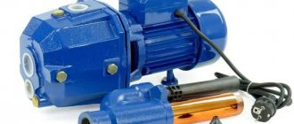
DIY installation and manufacturing
Most water flow sensors are included in the design of the devices, so they need to be installed only in the event of a breakdown and the need to replace them. However, there are cases when the water flow sensor must be mounted separately, for example, if it is necessary to increase the water supply pressure. This is due to the fact that in the central water supply system, the pressure is low and does not reach the norm. And in order to turn on a gas boiler in hot water supply mode, you need good pressure.
In such situations, an auxiliary circulation pump is installed, which is equipped with a water flow sensor. First the pump is installed, and then the sensor. It follows that as soon as water starts flowing, the sensor will turn on the pump and the pressure will begin to increase.
Pressure booster pump for Grundfos UPA 15-90 water supply system with built-in water flow sensor
Making a water flow sensor with your own hands is not difficult. First you need to install the camera, then you need to cut out three plates, they should be mounted horizontally, there should be no contact between them and the bulb. For a simple design, one float will be enough.
It is rational to install the fitting on two adapters; the valve must withstand a pressure of at least 5 Pa.