The greater the load, the greater the length of the beam span. In construction, beams are most often used as an element of interfloor ceilings, columns, bridges and overpasses. Beams are classified according to various features: from the external shape and location of the edges of the shelves to the features of production and methods of application. There are two main types of I-beams:
- Hot rolled I beam
- Welded I-beam
A hot-rolled beam is made from a steel billet using the hot rolling method
more details
About I-beam
About welded I-beam and its production
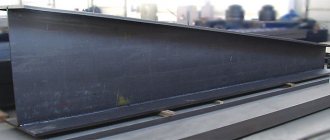
An I-beam is one of the main types of profiles used in construction and, in general, one of the most famous and widespread types of profiles in the world. The I-beam is used as a load-bearing element of floors and column structures. Thanks to the use of welding, it is possible to create beams of different standard sizes, which with modern production technology cannot be realized in hot-rolled beams. Welding I-beams allows you to most rationally combine the sizes and thicknesses of the shelves with the vertical wall. Varying different thicknesses of walls and flanges allows you to select the optimal cross-sectional area of the beam and thereby reduce the weight of the beam and the entire metal structure as a whole.
A welded I-beam has high rigidity with low weight and its characteristics significantly exceed the rigidity of a square profile and angle.
Various grades of steel are used in the manufacture of a welded beam - when the most stressed sections of the beam are made of high-strength steel, and the least stressed sections are made of low-carbon steel, which reduces the cost of the beam, and the possibility of manufacturing beams of a given length allows saving on waste.
About the I-beam...
Classification of hot-rolled I-beams
According to the cross-sectional shape, hot-rolled I-beams are divided into two groups: with a slope of the internal edges of the flanges (manufactured according to GOST 8239-89 and 19425-74 for special types) and with parallel edges of the flanges (GOST 26020-83).
I-beam with sloped internal edges of the flanges
Products manufactured in accordance with GOST 8239-89 have an acceptable edge slope of no more than 12%. Rolling accuracy: increased (“B”) and normal (“C”).
Special purpose beams (GOST 19425-74) are used for:
- “M” – structures of overhead tracks (the slope of the internal edges of the shelves is no more than 12%);
- “C” – reinforcement of mine shafts (slope can reach 16%).
Manufacturing technology of welded I-beams
About welded I-beam and its production
It is better to build metal structures from a welded beam because... they are economically beneficial in the construction of buildings and structures. The use of welded I-beams as structural metal frame structures makes it possible not only to lighten structural elements that have an unreasonably large safety factor, but also to create a more economical shape of supports and cross-sections of individual elements, thereby reducing the weight of the metal structure. The manufacturing process of welded I-beams is economical and successfully competes with the production of beams by rolling.
more details
Additional functions of an I-beam in private housing construction
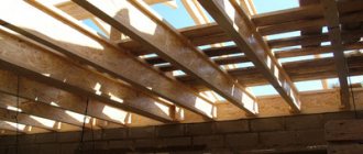
The floor itself does not necessarily have to consist only of metal I-beams. Often they are used only in the most intense places, and wooden I-beams are installed between the metal parts.
Why is that? The fact is that welding requires highly qualified workers. Further, in ordinary literature and Internet sites there is not that variety of components and ready-made design diagrams for installing such a ceiling; a competent engineer is really required here, and even we only give recommendations. In addition, metal is not cheap. And the quality of welding is very important. It must work for a long time, even under conditions of corrosion or changing loads.
Therefore, this option not only has the right to life, but is also quite practical:
And finally, a metal I-beam often serves as an additional functional element, which has value in any household:
Welding I-beam
About welded I-beam and its production
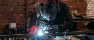
Welding an I-beam, the method of assembling the beam depends on the nature and design of the fixtures used and the designed method of welding the waist seams of the beam. Welding of long waist seams is performed using submerged arc machines. The beam is assembled from its three main elements (belts and walls), the waist seams are welded automatically, and then transverse stiffeners are installed and welded semi-automatically or manually. The assembly of I-beams is carried out using clamps and tacks or in a special jig. Automated equipment for the production of welded I-beams is also widely used today.
When welding a beam, the use of flux radically improves the welding process of the beam. The presence of a bubble of liquid flux, under the pressure of unmelted flux, eliminates splashing and scattering of liquid metal and thereby ensures excellent formation of the weld even at currents of up to 3000-4000 A.
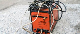
If during open arc welding with high-quality electrodes, metal loss due to waste and spatter reaches 20-30%, then when submerged arc welding these losses do not exceed 1-2%. Under a layer of flux, during submerged arc welding, the molten metal cools, which slows down the cooling process, which improves the conditions for the release of gases from the molten metal. The following types of welding equipment are used for welding I-beams:
more details
Notes[ | ]
- ↑ 12
Chair is a garden and hayfield in a mountain forest. Traditional Crimean polycultural plant community | Green Way - Trubachev O. N.
Indoarica in the Northern Black Sea region: Reconstruction of language relics. Etymological dictionary. M.: “Science”, 1999. - Galkina E. S.
Secrets of the Russian Kaganate. M.: “Veche”, 2002, p. 91 - Tauro-Scythians (undefined)
.
DEAR MILLENNIUM ESSAYS ABOUT ANCIENT CRIMEA
. PUBLISHING HOUSE "CRIMEA" SIMFEROPOL (1969). - Archived copy (unspecified)
(inaccessible link). Retrieved March 19, 2022. Archived April 2, 2022. - Strabo VI, 4, 2
- Tacitus XII, 17
- Ammianus Marcellinus XXII, 8, 33
Welding defects
Defects in the weld seam and around the weld zone include various deviations from technological parameters caused by negligence in work, violation of operating conditions and external causes, often beyond the control of the welder.
Defects can also be caused by violation of technological methods, both the welding process itself and poor-quality preparation of the products being welded, equipment malfunction, deviations from the quality standards of welding materials, the influence of weather conditions, and low qualifications of the welder.
The occurrence of defects is often associated with metallurgical and thermal phenomena that arise during the formation of the weld pool and its crystallization (hot and cold cracks, pores, slag inclusions, etc.). These defects reduce the strength and reliability of the welded joint, its tightness and corrosion resistance. All this can have a significant impact on the operational capabilities of the entire structure and even cause its destruction. Defects in welding seams can be external or internal. External defects of welding seams External defects of welding seams include violation of the size and shape of the seam, undercuts and other deviations that can be detected during an external inspection of the welded joint.
more details
Possible deformations
During the process of welding yourself, you can unwittingly make mistakes, which will subsequently lead to deformation of the beam. It is good if deformations appear before installation. It's worse if the beam bends when it is installed. Below you can see a picture with recommendations for avoiding deformations.
How to avoid most problems? Your finished weld joint should not be in tension. This is the most important rule. By incorporating it into your work, you can reduce the likelihood of deformation. Also, after welding the two parts, wait for a while, there is no need to continue welding immediately. This way you will not accumulate excess stress in the metal.
Cutting sheet for I-beam
A welded I-beam is made from strips (sheet metal strips). For cutting sheet metal for I-beams, industrial enterprises widely use thermal metal cutting machines.
Thermal cutting is the processing of metal (cutting blanks, gouging, creating holes) by heating.
Thermal cutting differs from other types in its high productivity with relatively low energy consumption and the ability to produce workpieces of any, no matter how complex, contour with a large metal thickness.
When cutting by oxidation, the metal in the cutting zone is heated to its ignition temperature in oxygen, then it is burned in a stream of oxygen, using the resulting heat to heat subsequent sections of the metal. Combustion products are blown out of the cut with a stream of oxygen and gases formed during metal combustion. Oxidation cutting includes gas-flame (oxygen) and oxygen-flux cutting.
more details
Assembling an I-beam
About welded I-beam and its production
A welded I-beam is made up of three long sheet elements (two chords and a web). Stiffening ribs are installed in high beams to increase the stability of compressed elements. The main seams in beams are the butt seams of the chords and the wall and the corner welds connecting the chords to the wall.
When producing welded beams in workshops, it is advisable to first weld the joints of the chords and the walls, since butt seams are the most critical, therefore, to reduce residual stresses, they should be welded in the absence of fastenings in the sheets being welded. When assembling a belt or wall, it is necessary that the longitudinal axes of the joined sheets lie in one straight line, the displacement of the joined edges from the plane of the sheets does not go beyond the permissible deviations, and the gap is maintained according to the drawing.
The method of beam assembly depends on the nature and design of the fixtures used and the designed method of welding the waist seams.
Currently, welding of long waist seams is carried out mainly by submerged arc machines. The beam is assembled from its three main elements (belts and walls), the waist seams are welded automatically, and then transverse stiffeners are installed and welded semi-automatically or manually. Welded beams are assembled using clamps and tacks or in a special jig.
more details
Docking Features
During installation work, the need to join I-beams often arises. The connection of I-beams can be made by welding, bolting or a combined method.
Docking by welding
This method is the most common because it ensures the preservation of the load-bearing capacity of the structure and requires minimal labor costs.
Method 1
The ends of the I-beams are welded to a metal gasket. With this joining method, welding seams are usually not cut.
Method 2
The second method involves the use of four overlays, which are welded to the outer plane of the shelves and on both sides of the I-beam wall. The work is carried out in the following sequence:
- The end edge of both profiles is chamfered, ensuring high-quality penetration. The beams are carefully positioned and welded around the entire perimeter.
- Next, you should prepare reinforcing linings, the material for which is structural sheet steel. The width of the overlays of beams welded to the shelves must correspond to the width of the shelf. The side trims are cut so that their height does not exceed the height of the wall.
- The finished overlays are laid directly on the weld, fixed with clamps and welded on all sides. The overlays on the I-beam walls are often made in the shape of a rhombus, this greatly simplifies the welding work.
Since welds are stress concentrators, connecting I-beams by welding is used for beams operating under moderate loads. In addition, the weld leg quickly ages, which leads to premature failure of the structure. To avoid this, the joints between the I-beams are treated with a special primer.
Joining steel I-beams using bolts
This joining method is especially effective when installing mobile structures, the elements of which have to be dismantled and reassembled. The advantages of detachable docking include the following factors:
- assembly of detachable structures does not require highly qualified service personnel;
- the bolted connection does not cause residual deformation of the profile, which often occurs during welding work;
- it is much easier to control the quality of joining than to check the quality of welds;
- bolted connections satisfactorily withstand shock and vibration loads.
The disadvantages of this connection include:
- the need to use additional reinforcing elements, which significantly increases the labor and metal intensity of the work;
- To ensure safety during operation, constant monitoring of bolt tightening is necessary, otherwise the fastening may become loose;
Fasteners made from carbon steels are susceptible to corrosion rather quickly.
Combined docking method
To create long I-beams, a combination of bolted and welded connections is practiced. Docking is carried out in the following order:
- The joined I-beams are connected through linings with fasteners made of high-strength and alloy steel grades.
- After installing the fasteners, the belts are welded.
- Technological windows are closed with plates and gaskets made of sheet steel.
To connect wooden I-beams, metal, wood and composite wall linings can be used, placed on both sides of the beam. Bolts and screws are used as fasteners, less often self-tapping screws or nails.
Taking into account the facts stated above, we can say that the I-beam is one of the most popular profiles in the construction of metal structures. The ability to withstand significant mechanical loads and the low specific weight of the I-beam can significantly increase the strength and reduce the metal consumption of the structure
Preparation of rolled sheet metal for the production of welded I-beams
About welded I-beam and its production
Often, rolled sheets supplied to production from a supplier have waviness and bulges. To assemble the beam, it is necessary to use only straight sheets that comply with the “GUIDELINES FOR METHODS OF EDITING ELEMENTS OF WELDED BRIDGE STRUCTURES” GOST 23118-99, GOST 21779-82.
If the sheet does not comply with GOST, to produce a welded I-beam it is necessary to perform a sheet straightening operation. Straightening is the operation of straightening sheet metal. Defects on metal parts and workpieces can form after heat treatment, welding, soldering, as well as after cutting sheet metal workpieces.
More details
Scope of application
As has already become clear, the main purpose of a metal beam is to receive and uniformly distribute the load on the load-bearing elements of the structure. According to construction practice and the theory of metal resistance, beams with H-shaped and T-shaped sections have much greater rigidity and strength than steel profiles with rectangular, square and round sections.
The metal frame, created using a T-beam or I-beam, has a rigid structure, high mechanical strength and resistance to external influences. Additional stiffening ribs allow structures to withstand enormous static and dynamic loads for a long time.
Main areas of application of metal products:
- Construction of hangars, production workshops, warehouses, shopping and entertainment centers;
- Construction of high-rise buildings and low-rise buildings, roofing work, strengthening of interfloor ceilings and columns;
- The construction of residential buildings based on a metal frame is considered a fairly new direction;
- Construction of overhead tracks and crane trestles in production workshops and construction sites;
- Reinforcement of mine shafts, underground tunnel arches;
- Construction of bridges and overpasses.
An important factor when designing a building is the correct calculations and the correct selection of materials. Regardless of the steel grade, section shape and beam type, calculations are performed according to the following scheme. The first step is to draw up a calculation scheme with the determination of internal forces. Based on the calculation results, a metal product with optimal geometric parameters and technical characteristics is selected. This approach ensures maximum strength and stability of the structure at minimal cost. It is for this reason that we strongly recommend seeking professional help if it is necessary to erect even a seemingly simple carport, not to mention more serious structures.