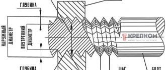
Purpose of thread and its elements
The thread is the main element of the screw drive and threaded connection. It consists of a series of bulges and depressions on the torsion bodies, which provides a fastening that can withstand high loads. Cutting is used as a method of combining or compacting structural links.
The thread provides a fastening that can withstand high loads.
Its main elements are:
- internal, external and middle diameters;
- profile is a cross section of a cut with a plane passing through the main axis of the part under consideration;
- profile angle - the angle formed by the sides of the profile;
- profile height is the length of the segment between the minimum and maximum cutting points in the cross-sectional plane of the axis in the direction orthogonal to the cutting guide;
- pitch - the length of the gap between two points of adjacent identical turns, measured parallel to the axis of the thread.
Short description
Tapered pipe thread is a special type of thread that is similar in shape to a cone, that is, a decrease in diameter towards the end of the part. The profile of such a connection should exclusively have an angle of 55 degrees, and the cutting itself has rounded depressions and peaks.
In this case, the pitch is indicated by the corresponding number of turns per inch and they are cut at a slope of 1°47′24″, which, in turn, must correspond to a taper of 1:16. The reliability of the connection lies in the fact that the more turns, the higher the tightness.
In addition, there is a metric conical thread in the connections of the external cone-shaped with the internal cylindrical with a designated profile, which, according to GOST 9150-2002, must have flat-cut cavities.
One of its main advantages is that tapered threads can be cut directly on site using thread-cutting dies or clamps. But in order to make the correct cutting, it is necessary to use special pipe cleats, since the torque during the creation of the grooves is quite large.
The name itself means that its dimensions are indicated in inches, since it refers to the English measurement system, for example, 1/8, 1/4, 1/2 inches.
What is the image and designation of the thread
The designation allows, based on a combination of letters and numbers, to understand what type of cutting is presented for analysis. It includes: type, pitch and stroke, accuracy class and number of the corresponding standard. For a better understanding of the operation, an image is used - this is a drawing in which, in accordance with GOST, a structural element with a threaded surface is presented.
The diagram helps create a visual representation of the shape and geometric features of the carving.
Designation on drawings
When moving the contour of a flat figure (circle, triangle, trapezoid, etc.) along a spiral line, a cut appears on the surface of a given shape. The methods of its presentation in drawings are regulated in specially developed international documentation (GOST), which was created for an unambiguous interpretation of the designation of pain.
Image of external threads on shafts
The external cutting gauge appears throughout as a solid main line. In the image obtained by projection onto a plane parallel to the rod axis, the internal thread is indicated by a thin permanent line along its entire length. In a drawing with a projection of the orthogonal guide of the rod, the internal diameter of the thread should be depicted as a thin continuous arc constituting 3⁄4 of the main circle. If it is necessary to show the carving as invisible, then it is represented by identical broken lines along the internal and external diameter.
External thread on shafts.
Image of internal threads in parts holes
In the holes everything is different. The internal diameter of the thread is indicated by a continuous main line. In the image obtained by projecting onto the plane of the orthogonal axis of the rod, the external thread is shown as a thin permanent line. In the drawing with the projection of the orthogonal guide of the rod, the external diameter of the thread is represented by a thin continuous arc, which is 3⁄4 of the circle.
Internal threads in the holes of parts.
MAIN DEVIATIONS
4.1. The numerical values of the main deviations of the diameters of external and internal threads must correspond to those indicated in the table. 7.
Table 7
| Pitch P , mm | External thread | Internal thread | |||||||
| Thread diameter | |||||||||
| d; d2 | D1 ; | ||||||||
| Main deviation, µm | |||||||||
| es | EI | ||||||||
| d | e | f | g | h | E | F | G | H | |
| 0,2 | — | — | -32 | -17 | 0 | — | +32 | +17 | 0 |
| 0,25 | — | — | -33 | -18 | 0 | — | +33 | +18 | 0 |
| 0,3 | — | — | -33 | -18 | 0 | — | +33 | +18 | 0 |
| 0,35 | — | — | -34 | -19 | 0 | — | +34 | +19 | 0 |
| 0,4 | — | — | -34 | -19 | 0 | — | +34 | +19 | 0 |
| 0,45 | — | — | -35 | -20 | 0 | — | +35 | +20 | 0 |
| 0,5 | — | -50 | -36 | -20 | 0 | +50 | +36 | +20 | 0 |
| 0,6 | — | -53 | -36 | -21 | 0 | +53 | +36 | +21 | 0 |
| 0,7 | — | -56 | -38 | -22 | 0 | +56 | +38 | +22 | 0 |
| 0,75 | — | -56 | -38 | -22 | 0 | +56 | +38 | +22 | 0 |
| 0,8 | — | -60 | -38 | -24 | 0 | +60 | +38 | +24 | 0 |
| 1 | -90 | -60 | -40 | -26 | 0 | +60 | +40 | +26 | 0 |
| 1,25 | -95 | -63 | -42 | -28 | 0 | +63 | +42 | +28 | 0 |
| 1,5 | -95 | -67 | -45 | -32 | 0 | +67 | +45 | +32 | 0 |
| 1,75 | -100 | -71 | -48 | -34 | 0 | +71 | +48 | +34 | 0 |
| 2 | -100 | -71 | -52 | -38 | 0 | +71 | +52 | +38 | 0 |
| 2,5 | -106 | -80 | -58 | -42 | 0 | +80 | — | +42 | 0 |
| 3 | -112 | -85 | -63 | -48 | 0 | +85 | — | +48 | 0 |
| 3,5 | -118 | -90 | — | -53 | 0 | +90 | — | +53 | 0 |
| 4 | -125 | -95 | — | -60 | 0 | +95 | — | +60 | 0 |
| 4,5 | -132 | -100 | — | -63 | 0 | +100 | — | +63 | 0 |
| 5 | -132 | -106 | — | -71 | 0 | +106 | — | +71 | 0 |
| 5,5 | -140 | -112 | — | -75 | 0 | +112 | — | +75 | 0 |
| 6 | -150 | -118 | — | -80 | 0 | +118 | — | +80 | 0 |
Symbol for metric thread (GOST 8724-2002)
The definition of a thread includes the letter M (from the English metric system), the size of the gauge and the pitch of the thread, delimited by the sign “x”. Example: M8x1.25. It is possible not to specify a large step. Example: M8. If the thread is left-handed, then the letters LH are added. Example: M8x1-LH. The definition of a multi-start cut consists of the symbol M, the diameter, the sign “x”, the combination of Ph, the stroke, the symbol P and the pitch. For certainty, you can specify the number of visits.
Metric thread (GOST 8724-2002).
Symbol for trapezoidal thread (GOST 9484-81)
The definition of a single-cut trapezoidal cutting contains the abbreviation Tr, the value of the outer gauge and the pitch. Example: Tr16x4. For a multi-start trapezoidal cut, the definition includes: the combination of Tr, the external diameter, as well as the pitch and stroke. Example: Tr16x8(P4)LH.
Trapezoidal thread (GOST 9484-81).
Designation of thrust thread (GOST 10177-82)
The definition of a thrust thread must contain the letter S, the pitch and the value of the diameter. Example: S90-10. For left-sided cuts, additionally LH is indicated. If multi-pass cutting is considered, then its definition is made up of the symbol S, diameter, stroke and in brackets the letter P, the value of the step. Example: S80-20(P20).
Thrust thread (GOST 10177-82).
Designation of persistent reinforced thread (GOST 13535-87)
The definition of persistent reinforced cutting contains the letters S, as well as an angle of 45, caliber and pitch. Example: S45200-13. If the thread is left-handed, the letters LH are additionally indicated. If it is necessary to define a multi-start thread, then indicate the letter S, the angle 45, the diameter, the stroke and the symbol P along with the pitch value, highlighted in brackets. Example: S4520024(P12) - two-start, stroke value 24 mm, pitch - 12 mm. For left-sided cuts, additionally LH is indicated.
Reinforced thrust thread (GOST 13535-87).
TOLERANCES
3.1. The numerical values of the tolerances for the diameters of external and internal threads must correspond to those indicated in the table. 4 - 6.
Table 4
Diameter tolerances d
and
D1
| Pitch P , mm | External thread | Internal thread | ||||||
| Degree of accuracy | ||||||||
| 4 | 6 | 8 | 4 | 5 | 6 | 7 | 8 | |
| Tolerance, µm | ||||||||
| Td _ | T D 1 | |||||||
| 0,2 | 36 | 56 | — | 38 | 48 | 60 | — | — |
| 0,25 | 42 | 67 | — | 45 | 56 | 71 | — | — |
| 0,3 | 48 | 75 | — | 53 | 67 | 85 | — | — |
| 0,35 | 53 | 85 | — | 63 | 80 | 100 | — | — |
| 0,4 | 60 | 95 | — | 71 | 90 | 112 | — | — |
| 0,45 | 63 | 100 | — | 80 | 100 | 125 | — | — |
| 0,5 | 67 | 106 | — | 90 | 112 | 140 | 180 | — |
| 0,6 | 80 | 125 | — | 100 | 125 | 160 | 200 | — |
| 0,7 | 90 | 140 | — | 112 | 140 | 180 | 224 | — |
| 0,75 | 90 | 140 | — | 118 | 150 | 190 | 236 | — |
| 0,8 | 95 | 150 | 236 | 125 | 160 | 200 | 250 | 315 |
| 1 | 112 | 180 | 280 | 150 | 190 | 236 | 300 | 375 |
| 1,25 | 132 | 212 | 335 | 170 | 212 | 265 | 335 | 425 |
| 1,5 | 150 | 236 | 375 | 190 | 236 | 300 | 375 | 475 |
| 1,75 | 170 | 265 | 425 | 212 | 265 | 335 | 425 | 530 |
| 2 | 180 | 280 | 450 | 236 | 300 | 375 | 475 | 600 |
| 2,5 | 212 | 335 | 530 | 280 | 355 | 450 | 569 | 710 |
| 3 | 236 | 375 | 600 | 315 | 400 | 500 | 630 | 800 |
| 3,5 | 265 | 425 | 670 | 355 | 450 | 560 | 710 | 900 |
| 4 | 300 | 475 | 750 | 375 | 475 | 600 | 750 | 950 |
| 4,5 | 315 | 500 | 800 | 425 | 530 | 670 | 850 | 1060 |
| 5 | 335 | 530 | 850 | 450 | 560 | 710 | 900 | 1120 |
| 5,5 | 355 | 560 | 900 | 475 | 600 | 750 | 950 | 1180 |
| 6 | 375 | 600 | 950 | 500 | 630 | 800 | 1000 | 1250 |
Table 5
Diameter tolerances d2
| Nominal thread diameter d , mm | Step R , mm | Degree of accuracy | |||||||
| 3 | 4 | 5 | 6 | 7 | 8 | 9 | 10 | ||
| Tolerance Td2 , µm | |||||||||
| From 1 to 1.4 | 0,2 | 24 | 30 | 38 | 48 | (60) | (75) | — | — |
| 0,25 | 26 | 34 | 42 | 53 | (67) | (85) | — | — | |
| 0,3 | 28 | 36 | 45 | 56 | (71) | (90) | — | — | |
| St. 1.4 to 2.8 | 0,2 | 25 | 32 | 40 | 50 | (63) | (80) | — | — |
| 0,25 | 28 | 36 | 45 | 56 | (71) | (90) | — | — | |
| 0,35 | 32 | 40 | 50 | 63 | 80 | (100) | — | — | |
| 0,4 | 34 | 42 | 53 | 67 | 85 | (106) | — | — | |
| 0,45 | 36 | 45 | 56 | 71 | 90 | (112) | — | — | |
| St. 2.8 to 5.6 | 0,25 | 28 | 36 | 45 | 56 | (71) | — | — | — |
| 0,35 | 34 | 42 | 53 | 67 | 85 | (106) | — | — | |
| 0,5 | 38 | 48 | 60 | 75 | 95 | (118) | — | — | |
| 0,6 | 42 | 53 | 67 | 85 | 106 | (132) | — | — | |
| 0,7 | 45 | 56 | 71 | 90 | 112 | (140) | — | — | |
| 0,75 | 45 | 56 | 71 | 90 | 112 | (140) | — | — | |
| 0,8 | 48 | 60 | 75 | 95 | 118 | 150 | 190 | 236 | |
| St. 5.6 to 11.2 | 0,25 | 32 | 40 | 50 | 63 | (80) | — | — | — |
| 0,35 | 36 | 45 | 56 | 71 | 90 | — | — | — | |
| 0,5 | 42 | 53 | 67 | 85 | 106 | (132) | — | — | |
| 0,75 | 50 | 63 | 80 | 100 | 125 | (160) | — | — | |
| 1 | 56 | 71 | 90 | 112 | 140 | 180 | 224 | 280 | |
| 1,25 | 60 | 75 | 95 | 118 | 150 | 190 | 236 | 300 | |
| 1,5 | 67 | 85 | 106 | 132 | 170 | 212 | 265 | 335 | |
| St. 11.2 to 22.4 | 0,35 | 38 | 48 | 60 | 75 | 95 | — | — | — |
| 0,5 | 45 | 56 | 71 | 90 | 112 | (140) | — | — | |
| 0,75 | 53 | 67 | 85 | 106 | 132 | (170) | — | — | |
| 1 | 60 | 75 | 95 | 118 | 150 | 190 | 236 | 300 | |
| 1,25 | 67 | 85 | 106 | 132 | 170 | 212 | 265 | 335 | |
| 1,5 | 71 | 90 | 112 | 140 | 180 | 224 | 280 | 355 | |
| 1,75 | 75 | 95 | 118 | 150 | 190 | 236 | 300 | 375 | |
| 2 | 80 | 100 | 125 | 160 | 200 | 250 | 315 | 400 | |
| 2,5 | 85 | 106 | 132 | 170 | 212 | 265 | 335 | 425 | |
| St. 22.4 to 45 | 0,5 | 48 | 60 | 75 | 95 | 118 | — | — | — |
| 0,75 | 56 | 71 | 90 | 112 | 140 | (180) | — | — | |
| 1 | 63 | 80 | 100 | 125 | 160 | 200 | 250 | 315 | |
| 1,5 | 75 | 95 | 118 | 150 | 190 | 236 | 300 | 375 | |
| 2 | 85 | 106 | 132 | 170 | 212 | 265 | 335 | 425 | |
| 3 | 100 | 125 | 160 | 200 | 250 | 315 | 400 | 500 | |
| 3,5 | 106 | 132 | 170 | 212 | 265 | 335 | 425 | 530 | |
| 4 | 112 | 140 | 180 | 224 | 280 | 355 | 450 | 560 | |
| 4,5 | 118 | 150 | 190 | 236 | 300 | 375 | 475 | 600 | |
| St. 45 to 90 | 0,5 | 50 | 63 | 80 | 100 | 125 | — | — | — |
| 0,75 | 60 | 75 | 95 | 118 | 150 | — | — | — | |
| 1 | 71 | 90 | 112 | 140 | 180 | 224 | 280 | 355 | |
| 1,5 | 80 | 100 | 125 | 160 | 200 | 250 | 315 | 400 | |
| 2 | 90 | 112 | 140 | 180 | 224 | 280 | 355 | 450 | |
| 3 | 106 | 132 | 170 | 212 | 265 | 335 | 425 | 530 | |
| 4 | 118 | 150 | 190 | 236 | 300 | 375 | 475 | 600 | |
| 5 | 125 | 160 | 200 | 250 | 315 | 400 | 500 | 630 | |
| 5,5 | 132 | 170 | 212 | 265 | 335 | 425 | 530 | 670 | |
| 6 | 140 | 180 | 224 | 280 | 355 | 450 | 560 | 710 | |
| St. 90 to 180 | 0,75 | 63 | 80 | 100 | 125 | 160 | — | — | — |
| 1 | 75 | 95 | 118 | 150 | 190 | — | — | — | |
| 1,5 | 85 | 106 | 132 | 170 | 212 | 265 | 335 | 425 | |
| 2 | 95 | 118 | 150 | 190 | 236 | 300 | 375 | 475 | |
| 3 | 112 | 140 | 180 | 224 | 280 | 355 | 450 | 560 | |
| 4 | 125 | 160 | 200 | 250 | 315 | 400 | 500 | 630 | |
| 6 | 150 | 190 | 236 | 300 | 375 | 475 | 600 | 750 | |
| St. 180 to 355 | 1,5 | 90 | 112 | 140 | 180 | 224 | 280 | 355 | — |
| 2 | 106 | 132 | 170 | 212 | 265 | 335 | 425 | 530 | |
| 3 | 125 | 160 | 200 | 250 | 315 | 400 | 500 | 630 | |
| 4 | 140 | 180 | 224 | 280 | 355 | 450 | 560 | 710 | |
| 6 | 160 | 200 | 250 | 315 | 400 | 500 | 630 | 800 | |
| St. 355 to 600 | 2 | 112 | 140 | 180 | 224 | 280 | 355 | 450 | — |
| 4 | 150 | 190 | 236 | 300 | 375 | 475 | 600 | 750 | |
| 6 | 170 | 212 | 265 | 335 | 425 | 530 | 670 | 850 | |
Note. The values indicated in brackets should not be used if possible.
Table 6
Diameter tolerances D2
| Nominal thread diameter d , mm | Step R , mm | Degree of accuracy | ||||||
| 4 | 5 | 6 | 7 | 8 | 9 | |||
| Tolerance TD2 , µm | ||||||||
| From 1 to 1.4 | 0,2 | 40 | 50 | 63 | — | — | — | |
| 0,25 | 45 | 56 | 71 | — | — | — | ||
| 0,3 | 48 | 60 | 75 | — | — | — | ||
| St. 1.4 to 2.8 | 0,2 | 42 | 53 | 67 | — | — | — | |
| 0,25 | 48 | 60 | 75 | — | — | — | ||
| 0,35 | 53 | 67 | 85 | — | — | — | ||
| 0,4 | 56 | 71 | 90 | — | — | — | ||
| 0,45 | 60 | 75 | 95 | — | — | — | ||
| St. 2.8 to 5.6 | 0,25 | 48 | 60 | 75 | — | — | — | |
| 0,35 | 56 | 71 | 90 | — | — | — | ||
| 0,5 | 63 | 80 | 100 | 125 | — | — | ||
| 0,6 | 71 | 90 | 112 | 140 | — | — | ||
| 0,7 | 75 | 95 | 118 | 150 | — | — | ||
| 0,75 | 75 | 95 | 118 | 150 | — | — | ||
| 0,8 | 80 | 100 | 125 | 160 | 200 | 250 | ||
| St. 5.6 to 11.2 | 0,25 | 53 | 67 | 85 | — | — | — | |
| 0,35 | 60 | 75 | 95 | — | — | — | ||
| 0,5 | 71 | 90 | 112 | 140 | — | — | ||
| 0,75 | 85 | 106 | 132 | 170 | — | — | ||
| 1 | 95 | 118 | 150 | 190 | 236 | 300 | ||
| 1,25 | 100 | 125 | 160 | 200 | 250 | 315 | ||
| 1,5 | 112 | 140 | 180 | 224 | 280 | 355 | ||
| St. 11.2 to 22.4 | 0,35 | 63 | 80 | 100 | — | — | — | |
| 0,5 | 75 | 95 | 118 | 150 | — | — | ||
| 0,75 | 90 | 112 | 140 | 180 | — | — | ||
| 1 | 100 | 125 | 160 | 200 | 250 | 315 | ||
| 1,25 | 112 | 140 | 180 | 224 | 280 | 355 | ||
| 1,5 | 118 | 150 | 190 | 236 | 300 | 375 | ||
| 1,75 | 125 | 160 | 200 | 250 | 315 | 400 | ||
| 2 | 132 | 170 | 212 | 265 | 335 | 425 | ||
| 2,5 | 140 | 180 | 224 | 280 | 355 | 450 | ||
| St. 22.4 to 45 | 0,5 | 80 | 100 | 125 | — | — | — | |
| 0,75 | 95 | 118 | 150 | 190 | — | — | ||
| 1 | 106 | 13,2 | 170 | 212 | 265 | 335 | ||
| 1,5 | 125 | 160 | 200 | 250 | 315 | 400 | ||
| 2 | 140 | 180 | 224 | 280 | 355 | 450 | ||
| 3 | 170 | 212 | 265 | 335 | 425 | 530 | ||
| 3,5 | 180 | 224 | 280 | 355 | 450 | 560 | ||
| 4 | 190 | 236 | 300 | 375 | 475 | 600 | ||
| 4,5 | 200 | 250 | 315 | 400 | 500 | 630 | ||
| St. 45 to 90 | 0,5 | 85 | 106 | 132 | — | — | — | |
| 0,75 | 100 | 125 | 160 | — | — | — | ||
| 1 | 118 | 150 | 190 | 236 | 300 | 375 | ||
| 1,5 | 132 | 170 | 212 | 265 | 335 | 425 | ||
| 2 | 150 | 190 | 236 | 300 | 375 | 475 | ||
| 3 | 180 | 224 | 280 | 355 | 450 | 560 | ||
| 4 | 200 | 250 | 315 | 400 | 500 | 630 | ||
| 5 | 212 | 265 | 335 | 425 | 530 | 670 | ||
| 5,5 | 224 | 280 | 355 | 450 | 560 | 710 | ||
| 6 | 236 | 300 | 375 | 475 | 600 | 750 | ||
| St. 90 to 180 | 0,75 | 106 | 132 | 170 | — | — | — | |
| 1 | 125 | 160 | 200 | 250 | — | — | ||
| 1,5 | 140 | 180 | 224 | 280 | 355 | 450 | ||
| 2 | 160 | 200 | 250 | 315 | 400 | 500 | ||
| 3 | 190 | 236 | 300 | 375 | 475 | 600 | ||
| 4 | 212 | 265 | 335 | 425 | 530 | 670 | ||
| 6 | 250 | 315 | 400 | 500 | 630 | 800 | ||
| St. 180 to 355 | 1,5 | 150 | 190 | 236 | 300 | 375 | — | |
| 2 | 180 | 224 | 280 | 355 | 450 | 560 | ||
| 3 | 212 | 265 | 335 | 425 | 530 | 670 | ||
| 4 | 236 | 300 | 375 | 475 | 600 | 750 | ||
| 6 | 265 | 335 | 425 | 530 | 670 | 850 | ||
| St. 355 to 600 | 2 | 190 | 236 | 300 | 375 | 475 | — | |
| 4 | 250 | 315 | 400 | 500 | 630 | 800 | ||
| 6 | 280 | 355 | 450 | 560 | 710 | 900 | ||
Necessary cutting tools
Cutting is widely used in everyday life and in production, so tools for making cutting are widespread. There are several types of cutting devices:
- Thread cutters are multi-toothed tools in which the thread cutting process is more productive than the cutters. They are divided into cylindrical comb, disk, prefabricated comb, heads for high-speed milling.
- Dies are a multi-edged tool for creating external cuts. There are round, solid, sliding devices, and split dies.
- Threading heads are special products for cutting internal and external threads and have a number of advantages compared to round dies. Depending on the comb design, heads are available with round radial, flat tangential and flat radial dies.
- Taps are an axial tool consisting of several blades designed for cutting internal threads. The following types are distinguished: manual, machine, wrench, machine, master, etc.
- Thread cutters are a tool for precise machine cutting of internal and external threads. They are divided into rod, single-strand and multi-strand shaped.
How are connections of threaded parts designated?
All characteristics of conical pipe threads are specified in GOST 6211–81. Domestic standards are compatible with foreign analogues: ISO R7, DIN 2999, BS 21, JIS B 0203. This type of thread is designated by the English letters R (external) and Rc (internal). GOST describes the profile, dimensions and tolerances of the connection. The detailed drawing shows the characteristic features of the connection. Additional applications regulate the preparation of parts for work. A summary table of the main parameters of pipe threads is the basis for controlling the quality and dimensions of the product.
Particular attention is paid to how the connection designation is made. If two types of thread are used, they are written as a fraction. The numerator is the inner part and the denominator is the outer part of the compound. For example, Rp/R 3/4 LH. This means that the threads are left-handed, three-quarters of an inch nominal, the internal cylindrical and the external conical pipe. The combination of different types is often used in repair practice. This restores the functionality of plumbing and gas appliances. Tapered threads are preferable where reliable sealing is needed.
If you find an error, please select a piece of text and press Ctrl+Enter.
Source: stankiexpert.ru