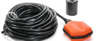
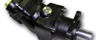
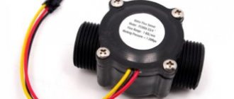
The operation of pumps is controlled using various devices, and one of the most common is a water level float switch. It can simultaneously perform the task of a water level sensor and be an actuator for controlling the pump. Floats for the pump are placed in containers.
One tank can accommodate several such switches, and they can solve different problems:
- Monitor the operation of the main pump.
- Serve as an overflow sensor.
- Ensure the operation of the auxiliary pump.
- Serve as an emergency level sensor.
With the help of such devices, the pumping apparatus is protected from the “dry running” mode. When filling different tanks, this element protects them from overflowing. Float switches for pumps come in light and heavy sizes. The former are more often used in drainage and water supply systems; the second - in drainage, rain and fecal wastewater. In stores, devices are sold with a cable length of 2, 3, 5, 10 m.
Float Connection Diagram
Plumbers recommend thoroughly rinsing the float with a hose at least once a month to prevent it from sticking to the pressure pipe or pump walls during daily operation.
In such a situation, installation is performed using a special rod. It is worth noting that the ability to provide reliable protection for pumping systems during dry-running operation is not the only positive quality of such devices.
The tilt at which the ball moves from one position to another is most often 70 degrees, but you should check this when purchasing the device. Water level sensor in the container (tank) // Automatic filling of the container // In addition to this, a considerable amount of electricity is saved, since the float switch allows you to use the pump only when necessary. Light elements attract customers with a low price, but can only work in clean water intended for drinking and domestic needs. Due to the lack of pores on plastic cases, dirt appears on them.
They should be located on the sides of the body inside, so that the ball, falling between them, makes contact.
If the difference is more than a meter, two separate sensors are used, installed at the required heights. This type of sensor is most effective when working with bulk solids.
The voltage level is usually V.
Tackle for summer fishing rod. Sliding float and weight. My fishing.
Reed switch device
The main actuator element of the reed switch is the reed switch. The device is a small glass cylinder filled with an inert gas or with air evacuated. Gas or vacuum prevents the formation of sparks and oxidation of the contact group. Inside the flask there are closed contacts made of a ferromagnetic alloy of rectangular cross-section (permalloy wire) coated with gold or silver. When exposed to a magnetic flux, the contacts of the reed switch are magnetized and repel each other - the circuit through which the electric current flows opens.
Rice. 6 Float vertical water level sensors
A similar pump control circuit, placed in the control cabinet, can be used when monitoring the level in a tank with liquid, if the reed switches are swapped, that is, SV2 will be at the top and turn off the pump, and SV1 in the depths of the water tank will turn it on.
Level sensors can be used in everyday life to automate the process when filling large containers with water using electric water pumps. The easiest types of reed switches to install and operate are those produced by industry in the form of vertical floats on rods and horizontal structures.
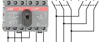
Possible connection diagrams for electric motor windings
Asynchronous electric motors have three windings, each of which has a beginning and an end and corresponds to its own phase. Winding designation systems may vary. In modern electric motors, a system has been adopted for designating windings U, V and W, and their terminals are designated by number 1 as the beginning of the winding and by number 2 as its end, that is, the U winding has two terminals: U1 and U2, the V winding has V1 and V2, and the W winding – W1 and W2.
However, old asynchronous motors made during the Soviet era and having the old Soviet marking system are still in operation. In them, the beginnings of the windings are designated C1, C2, C3, and the ends - C4, C5, C6. This means that the first winding has terminals C1 and C4, the second - C2 and C5, and the third - C3 and C6.
The windings of three-phase electric motors can be connected in two different patterns: star (Y) or delta (Δ).
Connecting an electric motor according to a star circuit
The name of the connection diagram is due to the fact that when the windings are connected according to this diagram (see figure on the right), visually it resembles a three-rayed star.
As can be seen from the electric motor connection diagram, all three windings are connected together at one end. With this connection (220/380 V network), a voltage of 220 V is applied to each winding separately, and a voltage of 380 V is applied to two windings connected in series.
The main advantage of connecting an electric motor according to a star circuit is the small starting currents, since the supply voltage of 380 V (phase-to-phase) is consumed by 2 windings at once, in contrast to the delta circuit. But with such a connection, the power of the powered electric motor is limited (mainly for economic reasons): usually relatively weak electric motors are turned on in a star.
Connecting an electric motor according to a triangle diagram
The name of this scheme also comes from the graphic image (see right picture):
As can be seen from the electric motor connection diagram - “triangle”, the windings are connected in series to each other: the end of the first winding is connected to the beginning of the second and so on.
That is, a voltage of 380 V will be applied to each winding (when using a 220/380 V network). In this case, more current flows through the windings; motors of higher power are usually switched on in a triangle than with a star connection (from 7.5 kW and above).
Connecting the electric motor to a three-phase 380 V network
The sequence of actions is as follows:
1.
First, let’s find out what voltage our network is designed for.
2.
Next, look at the plate that is on the electric motor, it may look like this (star Y / triangle Δ):
3.
After identifying the network parameters and the electrical connection parameters of the electric motor (star Y / delta Δ), we move on to the physical electrical connection of the electric motor.
4.
To turn on a three-phase electric motor, you need to simultaneously apply voltage to all 3 phases. A fairly common reason for electric motor failure is operation on two phases. This can happen due to a faulty starter, or due to phase imbalance (when the voltage in one of the phases is much less than in the other two). There are 2 ways to connect the electric motor: - using a circuit breaker or motor protection circuit breaker
When turned on, these devices supply voltage to all 3 phases at once.
We recommend installing a motor protection circuit breaker of the MS series, since it can be adjusted exactly to the operating current of the electric motor, and it will sensitively monitor its increase in the event of an overload. This device at the moment of starting makes it possible to work for some time at an increased (starting) current without turning off the engine. A conventional circuit breaker must be installed in excess of the rated current of the electric motor, taking into account the starting current (2-3 times higher than the rated current). Such a machine can turn off the engine only in the event of a short circuit or jamming, which often does not provide the necessary protection.
How to connect a wired sensor to Ajax and what else Transmitter can do
The Ajax security system includes sensors for motion, glass breakage, opening, impact and tilt, smoke, temperature and CO, and flooding. This is sufficient for most scenarios for protecting premises from burglary, fire and leakage. And when it is necessary to provide street security or use sensors that are not in our lineup, the Transmitter integration module will come in handy.
Ajax Transmitter is a wireless module for connecting third-party devices with wired outputs to the Ajax security system.
The module has alarm and tamper inputs (NC and NO contacts are supported), there is a 3.3 V power output for external sensors. Using Transmitter you can connect to the Ajax security system:
- Motion Sensor
- gas sensor
- curtain sensor
- perimeter sensor
- leak sensor
- glass break sensor
- temperature sensor
- vibration sensor
- wired reed switch
- panic button
- tamper
As well as any other sensors and devices with NC/NO (NC/NO) outputs.
For a connected device, it is possible to configure one of five types of alarms , which will best correspond to the essence of the threat:
- invasion
- fire
- medical care
- alarm button
- gas leak
Transmitter Features
- Turns third-party sensors into full-fledged Ajax devices.
- Can be placed in the sensor housing.
- Can be installed both indoors and outdoors (in a street sensor housing or in a sealed box).
- Can act as a power source for a connected device (3.3 V power output).
- Equipped with an accelerometer that raises an alarm if the module moves.
- Operates at temperatures from +50°C to −25°C and humidity up to 75% without condensation.
Transmitter only works with Ajax Hub. The device does not work with ocBridge Plus or uartBridge!
What devices can be connected to Ajax using Transmitter
Outdoor motion sensor
Transmitter appeared due to the urgent need for control of local areas. Although the current generation of the Ajax security system is intended for indoor security, European partners have been asking for outdoor motion sensors. A quick solution was a device capable of connecting Optex sensors with Ajax: IR barrier AX-200TFR, curtain BX-80NR, combined VXI-RDAM and other models. With the participation of Italian colleagues, in less than six months we developed Transmitter - a universal integration module that solved the problem of street security and at the same time made it possible to implement dozens of other scenarios.
Perimeter sensor type IR barrier
IR barriers are used when it is necessary to restrict access to an object from the outside, but at the same time allow movement within the territory.
Domestic gas sensor
Gas leak sensors are designed for timely detection of leaks and notification of this. This segment of sensors is popular because gas is difficult to detect in time, and the risk of disaster due to a leak is high. Sensors are classified according to the type of gas being detected: natural, carbon dioxide, carbon monoxide (CO). Since all gases vary in weight, there is no universal gas sensor. To detect a natural gas leak, the sensor must be placed as high as possible, carbon dioxide - as low as possible.
For private purposes and to ensure personal safety, “household gas leak sensors” are used.
☝️ Ajax has a fire sensor that detects rising temperatures, smoke and dangerous CO concentrations - FireProtect Plus.
Vibration sensor
The vibration sensor raises the alarm even during a break-in attempt, reacting to movement or even the slightest damage to the structure on which it is installed. Such devices are mounted on doors, windows and fences (they will report an attempt to climb over).
For the vibration sensor to work correctly with the Transmitter, it is necessary that the closing or opening lasts at least 0.6 seconds. Shorter short circuits and open circuits will be ignored by the false alarm protection system.
☝️ Ajax has a combined opening, shock and tilt sensor - DoorProtect Plus.
As well as any other sensors and devices with NC / NO outputs.
Problems that can be solved using Transmitter
Alarms when the temperature goes outside the specified range
To receive alarms when the temperature drops and/or rises above a preset level, an external thermostat is connected to the Transmitter. The temperature range is adjusted on the thermostat itself. To indicate the upper and lower limit temperatures, use NO contacts on the alarm loops, and place NC contacts on the Transmitter tamper contacts.
Gate Closing Confirmation
To control the closing of the gate and see the history of opening/closing, you can use the Transmitter in conjunction with a wired reed switch or limit switch.
Safe control
To protect a safe (a work of art or any other valuable object) and control its movement, you can use an external tamper paired with a Transmitter. When the safe is moved, the tamper button will be released and you and the security company will receive an alarm.
Water level control
The float sensor allows you to monitor the water level in the vessel and sends a notification if it is exceeded. Such sensors protect the pump from idling while pumping water and help control the water level in a pool or well.
Float design
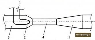
The equipment looks like a floating plastic box. In its inner part there is a metal ball and an electrical switch. When the location of the device changes, the steel ball closes or opens the connections of the toggle switch, from which a cable with 3 cords runs (as a rule, they are black, brown or blue).
The circuit is complete between the blue and black wires when the float switch for electric pumps is in the down position. If the device is placed in the upper position, then the contacts between the brown and black cord are closed.
An important factor must be taken into account: the supply cable must be moisture-resistant, and the plastic box itself must be sealed. The wire output is sealed with a mechanical seal and is equipped with a good mechanism to eliminate automatic damage in the wire. The separate cavity of the cable entry is filled with polymer resin, which prevents moisture from entering.
How does the switch work?
Despite the clear design, devices may differ in their method of operation:
Device for water supply systems. This is the simplest and most common way to use the product. The principle of operation is simple: when the product is on the surface, the pump begins to pump water from the container. The sensor automatically sends an electrical signal to the water pumping equipment. The station switches off when the switch reaches the bottom. The principle of operation in the sewer system. The electric fecal pump is turned on when the main control device rises to the surface. The auxiliary equipment begins to function when the sensor sinks to the bottom
It is important to know that one such float is capable of working with two pumping devices at once. At the same time, this does not affect the quality in any way; performance remains at the level
In addition, the two-pump design is highly efficient because there is no problem with fluid delivery.
Operating principle of float for pumps
Devices such as float switches can provide for different schemes for their use, and this also affects their principle of operation.
Water supply system, filling and emptying tank tank tank
With this operating scheme, at the moment of ascent, the float de-energizes the pump, which supplies water to the tank. The signal to turn on will only come when it reaches the bottom.
This situation occurs only when the container is empty. The float sends a signal to turn on the automatic water supply station the moment it is on the surface. The station can be turned off only when the float sinks to the bottom when the container is empty.
From the side of the float, a signal was received to close the valve or valve with a servo drive at the moment it was raised to the surface. The valve or gate valve will open only when it sinks to the bottom when the container is empty.
The operation of the float can only consist of notifying the control center or operator at the moment it is raised to the surface, which will correspond to the filling of the container. Information about the lack of water will arrive at the moment when the float reaches the bottom.
Sewage system
The float will turn on the fecal pumping equipment only when the main control device is raised up. The pumping unit is turned on when the control device is immersed in the bottom.
One float can simultaneously serve two pumping units: the first unit can supply water to the container, provided that the float is in the lower position . At this moment, the other pump is inactive. When the float is in the upper position, the second pump is turned on, whose task is to pump water out of the tank. At this time, the pump that supplies water to the tank is inactive. Despite its simplicity, the above scheme for using a float switch is not very effective, since this does not eliminate difficulties with the regular delivery of water at those moments when the tank is filling.
Installation
You can use one of several methods to install float switches. Even before installing this device, you should make sure that the current rating used to operate the pump is less than the maximum permissible current value, which is given in the technical specifications for this type of float. Among the known methods of installing a float switch for controlling water level, the easiest to implement is its placement in a tank , which involves the use of a float with a cable and a special sinker, which is attached to this device.
With this installation option, the sinker must be fixed on the cable, and then the length of the free-play arm of the float must be experimentally calculated. Using the latch, you need to secure the sinker to the cable. After this, the cable itself must be firmly fixed on the outside of the tank. Next, they move on to connecting the float switch to the pump. After this, the device can be used for its intended purpose.
The option of installing a float for pumps, which involves the use of a supply cable, can only be used in a situation where there is no risk of the main device getting caught or hanging in the tank itself and when there is only one float in it.
In some situations, it may be decided to install several floats at once to control the water level. In this case, they are mounted on a special rod. The latter most often uses fragments of a plastic pipe, which must be firmly fixed in the tank. After this, the floats are installed on the pipe, and they must be correctly positioned, adjusted and spaced along the length of the rod so that they do not create difficulties for each other for normal operation.
The cables that come from the float switches are connected to the rod using clamps . When choosing the number of float switches, attention should be paid to the number of pumps or the type and number of safety devices and control panels used. In some situations, the problem of ensuring reliable operation of float switches can be solved by using several rods.
When determining the installation diagram of float switches, their number and location, it is necessary to take into account the specifics of the place of their installation each time or focus on the project.
Operation, repair, maintenance
Compliance with the rules for operating floats will ensure their long-term operation.
When the float is included in the water supply and sanitation system, you should not waste time on its maintenance. If the device controls the operation of sewer or fecal pits, it is recommended to clean the float and pump from contaminants at least once a month with a stream of water supplied under pressure. This will prevent the float from sticking or sticking to the discharge pipe or pump. A broken float switch is replaced, and the replacement is carried out by specialists from service centers. When it is necessary to provide drinking water or remove contaminated wastewater, special devices are used together with pumps, in particular, a float switch. Since the device prevents dry-running, the service life of the pump is increased. A lot of energy is also saved, because, thanks to the float switch, the pump is activated only when necessary.
Why do you need an alarm in a Topas septic tank?
The emergency alarm is a simple design consisting of a float switch located in the receiving compartment of the septic tank and a warning lamp on the lid. Allows you to promptly notify the user about a malfunction of the Topas septic tank. The float monitors whether the liquid level is exceeded, and a lamp (buzzer) signals with a light or sound signal that the permissible level has been exceeded.
The alarm allows you to quickly see that something is going wrong in the septic tank and take corrective action. For example:
- you have poured more waste into the septic tank than it can absorb; no servicing has been carried out for a long time; faulty electrical equipment (compressor, float switches); blockage in the purified water outlet pipeline
So, you have decided that you need an emergency alarm and your hands are itching. Well, it's time to make it yourself, spending a little time and money. Below we will tell you how to do this.
Float level sensors (level alarms) PDU-T
Designed for simple tasks of monitoring the limit level of liquids. They are effective in cases where level measurement with other sensors (conductometric, ultrasonic, pressure sensors, rotary and vibration sensors) is technically impossible or unreasonably expensive due to their high cost.
Float level sensors (level switches) PDU-T can work both in conjunction with the devices OVEN SAU-M6, SAU-M7.E, SAU-MP, SAU-U, and independently, controlling actuators through an intermediate relay or contactor.
The presence of several design and material options in the PDU-T series will allow you to select a level sensor that will best suit your task in terms of installation method, material of the immersed part, output switching function, etc.
Methods for installing float level sensors (level alarms) PDU-T:
Operating principle and methods of installation of float level sensors (level alarms) PDU-T:
PDU-T1xx, PDU-T3xx, PDU-T5xx:
A permanent magnet in the sensor a reed switch is built into the sensor rod along which the float moves .
When the float is immersed in the liquid, it begins to move along the rod, causing the reed switch to operate and the sensor thus signals that the liquid has reached the limit level. Depending on the design, PDU-T sensors are installed horizontally or vertically in the container (see Fig. 1).
Fig.1. Example of installation of float level sensors (level alarms) PDU-T1xx, PDU-T3xx, PDU-T5xx
PDU-T601-x:
The PDU-T601-x float sensors include: a float with a contact group (NO+NC) and a ball inside, a cable of a certain length, depending on the modification of the sensor, and a weight that is placed on the cable. The cable is connected to the float through a sealed input. The weight located on the cable is intended to set the switching point for the contact state (upper level setting).
The sensor is suspended by the wire so that the float is at the height of the desired lower level of liquid in the container. In this position, the ball located in the sensor body presses on the contacts, closing one contact and opening the other relative to the common wire. The weight located on the sensor cable is lowered to the height of the desired upper level. When the container is filled, the liquid lifts the float up and when the float crosses the level at which the load is located, the ball rolls and switches the contacts to the opposite state (see Fig. 2).
Fig.2. Example of installation of float level sensors (level alarms) PDU-T601-x
Selection table for float level sensors (level alarms) PDU-T:
| Modification | Photo | Switching function | Switching voltage | Switching current | Output element | Material | Ambient temperature | ||
| DC | A.C. | DC | A.C. | ||||||
| PDU-T101 | 220 V | 240 V | 0.7 A | 0.5 A | Reed switch | Stainless steel steel | -20…+125 °C | ||
| PDU-T102 | 220 V | 240 V | 0.7 A | 0.5 A | Reed switch | Stainless steel steel | -20…+125 °C | ||
| PDU-T104 | 220 V | 240 V | 0.7 A | 0.5 A | Reed switch | Stainless steel steel + polypropylene | -10…+80 °C | ||
| PDU-T106 | 220 V | 240 V | 0.7 A | 0.5 A | Reed switch | Polypropylene | -10…+80 °C | ||
| PDU-T121-065-115 | 220 V | 240 V | 0.7 A | 0.5 A | Reed switch | Stainless steel steel | -20…+125 °C | ||
| PDU-T301 | 220 V | 240 V | 0.7 A | 0.5 A | Reed switch | Stainless steel steel | -20…+125 °C | ||
| PDU-T302 | 220 V | 240 V | 0.7 A | 0.5 A | Reed switch | Stainless steel steel | -20…+125 °C | ||
| PDU-T321-060-110 | 220 V | 240 V | 0.7 A | 0.5 A | Reed switch | Stainless steel steel | -20…+125 °C | ||
| PDU-T501 | 220 V | 240 V | 0.7 A | 0.5 A | Reed switch | Polypropylene | -10…+80 °C | ||
| PDU-T502 | 220 V | 240 V | 0.7 A | 0.5 A | Reed switch | Polypropylene | -10…+80 °C | ||
| PDU-T505 | 220 V | 240 V | 0.7 A | 0.5 A | Reed switch | Stainless steel steel | -20…+125 °C | ||
| PDU-T601-2 | 220 V | 220 V | 10 A | 10 A | Relay | Polypropylene | -10…+80 °C | ||
| PDU-T601-5 | 220 V | 220 V | 10 A | 10 A | Relay | Polypropylene | -10…+80 °C | ||
Selection rules
When purchasing a liquid level sensor in a tank, you need to take into account several factors; if they are observed, the device will work correctly and reliably. First of all, you need to determine the type of liquid medium and its density, the level of danger to humans. What matters is the material used to make the container and its volume—the operating principle of the selected sensor depends on these parameters.
The next point that you need to pay attention to is the purpose of the device; it will be used to control the minimum and maximum liquid levels or to constantly monitor the filling of the tank. When choosing industrial sensors, the number of criteria can be expanded; for household alarms and level meters, it is enough to take into account the volume of the tank and the type of device
At home, home-made devices are used - they work no worse than factory models
When choosing industrial sensors, the number of criteria can be expanded; for household alarms and level meters, it is enough to take into account the volume of the tank and the type of device. At home, home-made devices are used - they work no worse than factory models.