A hydraulic pump is a device that converts the mechanical energy of an engine into oil energy, with the help of which fluid can move vertically, horizontally, or in a circle, depending on the type of operation of the device.
The operation of the high pressure hydraulic pump is based on the piston-piston principle, and is quite simple and stable. The liquid can be taken from any source or reservoir.
Areas of application of the high pressure pump.
Due to their durability and high performance, hydraulic pumps are used in a large number of industries:
• Cleaning from dirt using a powerful jet of water supplied at high pressure
• For street cleaning
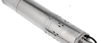
• Submersible and engineering pumps
• To clean pipes from contamination
• For extinguishing fires.
But in reality, most examples of the use of such a device are seen in car washes, where they are used to quickly and efficiently clean a car from various types of contaminants in order to wash off the detergent.
You can select the necessary accessories for high-pressure pumps, including sprayers, pressure regulators, and other devices with which you can configure the device as you need.
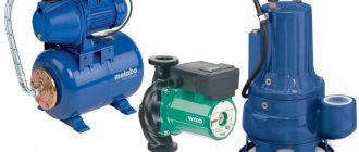
The high pressure hydraulic pump converts mechanical energy into hydraulic energy. Regardless of the device model, the principle of pushing out liquid is the same. They are divided into several types:
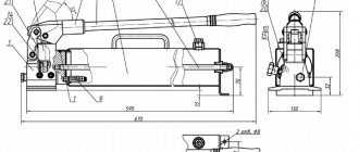
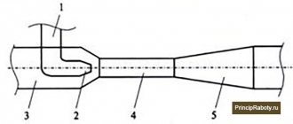
Design and diagram of a manual hydraulic pump
Diagram of a hydraulic hand pump
The manual hydraulic pump consists of two main parts, the pumping unit (1) and the hydraulic tank (2). They are connected to each other by a pin (3). You need to fill the liquid through the hole, having first unscrewed the plug that closes it (4). The handle (6) with the lever (7) drives the plunger (8) of the first and second stages, made as one part. The pumping unit has a two-stage structure. Stage number one, with reduced pressure and higher productivity, serves to accelerate the movement of the hydraulic cylinder plunger. Stage number two, at high pressure and lower capacity, serves to obtain the operating force of the actuator. Overload protection is provided by a safety valve (9). Pressure is released and hydraulic fluid is extracted from the cylinder cavity into the tank using a screw (10).
Lamellar
In these hydraulic machines, the plates placed on the rotor do the main work. Special springs strengthen their pressure against the stationary body. Adjacent elements become limiters of the volumetric chamber, in which the working medium, when the rotor rotates, enters from the supply cavity to the discharge cavity. The presence of two or more suction areas and the same number of entry zones into the system is characteristic of double- or multiple-acting designs.
You need to know: only single-action mechanisms can be regulated.
Advantages of vane pumps:
- Reduced pulsation.
- Reduced operating noise.
- Reduced requirements for contamination of the transported medium.
- Adjustable working volume.
Minuses:
- The rotor bearings are heavily loaded.
- Low pressure.
- Difficulty in sealing the plates at the ends.
- Low maintainability.
G12 is a popular brand of single- and double-flow plate structures.
Working principle of a manual hydraulic pump
Before starting to work with any pump, be sure to inspect the tool and if cracks and chips are found on the surface, do not use it. It is important to check whether the high pressure hose is tightly connected to the hand pump.
Work algorithm:
- We connect the pump to the hydraulic system with a quick-release coupling;
- Turn the valve all the way clockwise.
- Using progressive movements, pump the pump handle up and down. As a result, oil is pumped into the system from the pump. At the same time, pressure builds up in the system, and the piston of the hydraulic tool moves, into which we pump oil.
- In a situation where the working piston of the system into which oil is poured reaches its final position, increased pressure will be created in the system, as a result it will be impossible to pump oil. Then it is necessary to stop the pump to avoid failure of the device.
- In order to lower the pressure in the system, you need to slowly turn the valve all the way counterclockwise. As a result, oil from the system will flow back into the pump. This occurs due to the return of the piston to its original position.
- After finishing pumping oil, you should inspect the hydraulic system for oil leaks, and you should also inspect the pump. If leaks are found, they should be corrected immediately.
Where are hydraulic pumps used?
The way a hydraulic pump works determines its main application. Such equipment is in demand in the design of hydraulic machines, for the operation of which an uninterrupted supply of water and oil is important. It is indispensable in the operation of excavators and heavy construction equipment. Various models of hydraulic pumps are used on construction sites, car washes, in pipeline cleaning systems, in municipal equipment, in the forestry and oil refining industries, in the automotive and engineering industries, in the railway industry, etc.
Malfunctions and their elimination
- The manual hydraulic pump does not supply pressure. The main reasons for this behavior may be the lack of hydraulic fluid in the tank or the drain valve is not closed. In any case, it is worth checking these versions; if the tap is still closed and there is liquid, then perhaps the reason is that the suction or discharge valve is clogged. Then you will have to disassemble and wash the hydraulic pump valves.
- Oil (hydraulic fluid) is leaking in the gap located between the body and the plunger. In this case, it is highly likely that the O-rings are worn out or damaged. It is recommended to replace them immediately to prevent failure.
- Does not produce the performance specified in the data sheet. Most likely the filter element of the manual hydraulic pump is clogged. It is recommended to thoroughly rinse the filter element.
- Does not develop the pressure specified in the technical data sheet. The safety valve is not adjusted correctly. You need to set the safety valve to the pressure indicated in the data sheet.
Valve symbols – 2
2) FLOW DISTRIBUTION VALVE
Check valve
A check valve opens to allow oil to flow in one direction and closes to prevent oil from flowing in the opposite direction.
Spool valve
The control spool valve symbol uses a complex closed system that has a separate rectangle for each position.
Four-hole valve
Typically a four-hole valve will have two compartments if the valve has two positions, or three compartments if the valve has a center position.
Lever control symbols
Lever control symbols represent a lever, pedal, mechanical controls or pilot line located on the edge of the compartment.
How to choose the right hydraulic manual pump?
Choice
Three main selection factors:
1. The hydraulic pump tank must be larger than the hydraulic cylinder capacity.
2. Manual hydraulic pumps come in two types: single-acting and double-acting, pay attention to this parameter.
3. The pressure level should match what you need for work. Select a hydraulic pump with a pressure equal to or greater than the maximum pressure of the hydraulic cylinder.
Specifications and selection options
The main technical characteristics of the hydraulic pump are:
- Rotation speed, rpm.
- Working volume displaced per shaft revolution, cm3/rev.
- Operating pressure.
Remember! The basic units for measuring pressure have the following ratio: 1 atm=1.013 bar=0.101 MPa=1.03 kgf/cm2.
The selection of a pump for a specific hydraulic system is made taking into account the following criteria:
- Type of element that displaces liquid - piston, gear, plate.
- Requires a manual or electric hydraulic pump.
- Working pressure limits.
- What viscosity medium can the mechanism work with?
- Working volume.
- Frequency interval of operation.
- Ease of maintenance.
- Dimensions.
- Price.
Is it worth making a manual hydraulic pump yourself?
At the moment, hand-made pumps are almost never found. Despite this, you can make a hydraulic pump with your own hands. We will need a steel tank. The body will be made from it. To control the pressure in the tank you need a valve. It needs to be secured at the top with a washer. A lever is installed to control the closing valve. A cast iron pipe may be suitable. Use a pressure gauge to monitor pressure. In the end, you will end up with a device that will not withstand pressure of more than 4 atmospheres. With all this, a homemade hydraulic pump will take up a lot of space and be inconvenient to carry. The disadvantage of homemade hand pumps is their low efficiency; quite a lot of force will be required to activate the pump. Also, homemade devices are very unreliable. And if you take into account all the disadvantages, then spending resources on creating a homemade manual hydraulic pump is very ineffective. That is why they are not common.
Hydraulic motor
Like a cylinder, a hydraulic motor is a drive, only a rotary drive.
The principle of operation of a hydraulic motor is exactly the opposite of the operation of a hydraulic pump. The pump pumps fluid and the hydraulic motor is powered by this fluid. As we wrote earlier, a hydraulic pump converts mechanical energy into pressure energy and kinetic energy of the fluid. The hydraulic motor converts hydraulic energy into mechanical energy.
With hydraulic drive, pumps and motors work together. The pumps are mechanically driven and force fluid into hydraulic motors.
The motors are driven by fluid from the pump and this movement in turn rotates the mechanical parts.
Manual hydraulic pumps NRG
NRG hydraulic pumps are very reliable devices and are very common here in Russia as they are produced here. The NRG line of pumps contains devices with distributors. The letter “P” is usually placed at the end of the designation of such instruments. This letter means that the tool can work with double-acting hydraulic devices. Let's consider several models of NRG manual hydraulic pumps:
NRG pumps
- Model nrg-7020R. Creates a maximum pressure of 700 bar. And it has a nominal tank volume of 2 liters. The kit includes a hydraulic distributor that allows you to work with both single- and double-acting devices.
- Model nrg-7007. Also creates a pressure of 700 bar. The nominal tank volume is 0.7 liters. The advantages of this model are the presence of a safety valve, minimal force on the handle, and two stages of oil supply. This tool is designed for single-acting hydraulic tools with a spring return rod.
- Model nrg-67016R. The nominal tank volume is 14 liters. Handle force 55 kg. Pressure maximum 4 MPa. Capacity is 115 cubic cm. Such a device weighs as much as 30 kg and is quite large. Suitable for a small car service.
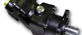
Subtypes of piston hydraulic pumps
Devices of this type are manual, radial and axial piston.
- Due to the simplicity of their design, hand pumps
- for powering hydraulic motors used in complex systems of auxiliary mechanisms;
- to create an emergency source for systems requiring hydraulic energy.
The pressure that manual units can provide does not exceed 50 MPa. The most common models of devices are with pressures up to 10-15 MPa. Their maximum working volume is 70 cm3. According to the operating principle, there are single- and double-sided hand pumps. The advantages of such equipment include simplicity of design, reliability and the absence of a drive motor. The disadvantages are rather low performance.
- Radial piston units are applicable for systems in which the pressure exceeds 40 MPa. Devices of this type can create and maintain pressure levels of up to 100 MPa for a long time. The rotation speed is usually up to 1500-2000 rpm, and can reach 3000 rpm in pump models with a displacement of up to 2-3 cm3/rev.
Pumps from this category can be equipped with an eccentric rotor or shaft. The latter option is in greatest demand due to the simplicity of its design.
- Axial piston devices are most in demand when arranging modern hydraulic drives. Their main advantages are high power density and high efficiency. Devices of this type can create pressure up to 40 MPa and operate at speeds up to 4000 rpm. It is worth noting that there are models of units with rotation speeds up to 20,000 ohm/min.
A wide range of models includes pumps of different designs and operating characteristics, equipped with an inclined block or an inclined disk.
What types of gear hydraulic pumps are there?
The design of devices of this type is based on two rotating gears. Such equipment is ideal for systems with pressures up to 20 MPa, used in road and agricultural machinery, lubrication systems and mobile hydraulics. Gear pumps also supply hydraulic energy to additional mechanisms in complex systems. Their main advantages are compact size, simplicity of design and low weight. But gear pumps also have disadvantages. Such devices have low efficiency (up to 0.85) and low operating pressure. The rotation speed in gear pumps is up to 5000 rpm.
There are external and internal gear pumps. Units of the first type operate due to the movement of gears. Their disadvantages include high pressure pulsation, low efficiency and a relatively low level of pressure generated. Devices of the second type are free from some of these disadvantages. Due to less pulsation and minimal noise during operation, they are widely used in stationary units, as well as in mobile equipment used in enclosed spaces.
A separate subtype of units with internal gearing are gerotor pumps. Such devices are applicable for systems with pressures up to 15 MPa and liquid supply up to 120 l/min. Their rotation speed is up to 1500 rpm. There are also rotary-screw devices capable of creating pressure up to 20 MPa. Their production is a rather complex task, so such devices are used in specific hydraulic systems.
Hydraulic vane pumps and their types
The design of such equipment is based on plates that perform reciprocating movements as the rotor rotates. Plate devices are used in systems with pressures up to 21 MPa and rotate at frequencies up to 1500 rpm. Single and double acting units are available in a wide range. Devices of the second type differ from the first by the presence of two zones of suction and liquid injection.
Summary, pros and cons of hydraulic hand pumps.
Pros:
- Easy to use;
- Do not require any additional energy source;
- High maintainability;
- Have high mobility;
Minuses:
- Low performance;
- Muscular strength of the operator is needed, therefore, additional load on the operator;
Bottom line, it is reasonable to use a manual hydraulic pump in small workshops and mobile services, where there is no need to pump in large volumes of oil and build up significant pressure. In general, hand pumps are very convenient, and most importantly, they are mobile since they do not depend on any energy sources.
Hydraulics and operation
Three elements of work
When there is any work, then certain conditions are necessary to perform this work. You need to know how much force is needed. You need to decide how quickly the work needs to be done and you need to determine the direction of the work. These three operating conditions: force, speed and direction are used in hydraulic terms as shown below.
Line (stream) symbols
Working, pilot and drain lines
A hydraulic hose, pipe, or other conduit that moves oil between components of a hydraulic system is indicated by a single line.
The working line (suction, discharge and return) is indicated by a solid line.
The pilot line is indicated by a dotted line with long dashes
The drainage line is indicated by a dotted line with short dashes
Connection/Transition Lines
To show that two intersecting lines are not connected, we use a short loop on one of the lines at the intersection.
The connection between two intersecting lines should be indicated by a dot at the junction.
Miscellaneous
Tank
A rectangle with a long side horizontally is a symbol of a tank. The open top symbol indicates a vented tank. The closed top symbol indicates a sealed tank.
Battery
The accumulator is oval in shape and may have additional parts to indicate spring pressure or gas charge.
Oil cooler
The oil cooler is shown as a square, rotated 45° and has connections at the corners.
Filter/Strainer
Dotted line inside a rotated square
Valve symbols – 3
3) HITACHI FOUR FLOW DIRECTION VALVE
Hitachi 4-Way Valve Symbols are similar to the 4-Way symbol, but with added connections and flow channels to show the bypass port.
Symbols for cylinder and motor spools are shown in the figure. Please remember that these symbols only show spool valves. The control valve block also shows the relief valves and connections to the body.
4) REducer VALVE
The pressure reducing valve symbol is shown in the figure and includes a normally closed valve with a built-in check valve.
The working process:
The pressure reducing valve is installed on the winch motor of the hydraulic crane.
(a) When the load is lowered, back pressure is created because there is a check valve.
(b) The pressure in the pressure line increases, the pilot line opens the valve to direct the flow of oil from the engine through the valve into the return line. This ensures protection against free fall of the load.
5) THROTTLE SYMBOLS
The basic throttle symbol means restriction.
6) SLOW RETURN VALVE
Adjustable throttle with built-in check valve.
The working process: