Hacksaw cutting machine 8725 is a stationary cutting machine designed for machine cutting of rolled metal (including pipes, rods, channels, angles and other shapes) in individual or continuous production.
Features of the 8725
The 8725 hacksaw cutting machine is distinguished by the following key features:
- cutting is performed at a right angle to the axis of the product or at an angle (up to 45°);
- equipment accuracy class N (GOST 8-82E);
- climatic version of the machine UHL 4 (GOST 15150-69).
Hacksaw cutting machine 8725 is an industrial metalworking equipment used in individual and mass production in tool and mechanical repair shops.
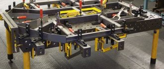
General view of the 8725 machine with designation of components
| № | Name | Designation |
| 1 | bed | 8725.10.000 |
| 3 | Drive unit | 8725.30.000 |
| 4 | Fencing | 8725.32.000 |
| 5 | Vise | 8725.41.000 |
| 6 | Cooling | 8725.60.000 |
| 7 | Hydraulic drive | 8725.80.000 |
| 8 | Electrical equipment | 8725.90.000 |
Location of controls
- Input switch.
- Control button “Start” of the machine drive
- Handle for fixing the saw frame in the upper position
- Handwheel for manual movement of the vice
- Hydraulic drive control handle
- The automatic shutdown of the machine is in the upper position of the saw frame.
- Control button “Stop” of the machine drive.
Kinematic diagram of machine 8725
The movement from electric motor 1 is transmitted through a V-belt transmission and two stepped pulleys to drive shaft II, pulley 4, freely rotating on shaft II, is interlocked with gear 3. Through a gear pair 3 and 5, the movement is transmitted to shaft III at the other end of which a crank disk 10 is attached finger 9.
The saw frame receives reciprocating motion from the crank disk through connecting rod 13. Its movement frequency per minute is 120 (I stage) and 48 (II stage). To obtain the frequency of movement of the saw frame 62 (III stage) and 94 (IV stage), it is necessary to reinstall the drive pulley 2 by turning it 180°.
On shaft III between the two supports there are eccentric journals, from which the movement is transmitted by connecting rods to the pistons A and B of the hydraulic pump. The pistons pump oil into the distribution valve D, from where it flows to the working cylinder C. The piston of this cylinder is connected to the sleeve using articulated rods. Thus, the lifting and launching of the saw frame, as well as the working feed during cutting, is carried out from a hydraulic drive.
The hydraulic drive is controlled by handle E, which can be locked in position (Fig. 8.): I-“Inaction”, II- “Lowering”, III-“Lifting”, IV-“Slow cutting” and “Fast”.
Upon completion of cutting the workpiece in the lowest position of the saw frame, the bar K, attached to the saw frame, strikes the rail 6 and moves it. The rack, through the intermediate gear 7, transmits movement to gear 8, which is rigidly connected to the shaft of the distribution valve. In this case, the crane is installed in the saw frame lifting position. The saw frame rises until it presses the limit switch. This opens the electrical circuit, turning off the main drive motor.
The hydraulic drive of the hacksaw machine 8725 is controlled by handle E, which can be locked in the following positions: 1-“Inaction”, 11-“Lowering”, 111-“Lifting”, 1V-“slow cutting” and “Fast”. Upon completion of cutting the workpiece in the lowest position of the saw frame, the bar K, attached to the saw frame, strikes the rail 6 and moves it. The rack, through the intermediate gear 7, transmits movement to gear 8, which is rigidly connected to the shaft of the distribution valve. In this case, the crane is installed in the saw frame lifting position. The saw frame rises until it presses the limit switch. This opens the electrical circuit, turning off the main drive motor.
All hydraulic equipment of the machine is mounted in the pump housing. Piston pumps 1 and 2 suck oil from the oil reservoir through filters 6 and 7, check valves 9 and 10, located in the control valve body, and supply oil to the distribution valve through channels 15 and 16.
Bed.
The bed has a box-shaped shape; the main components of the machine are mounted on it (Fig. 2). The lower part of the frame contains a reservoir for cooling liquid. An electric cooling pump is also installed here. The oil reservoir for the hydraulic drive is cast together with the frame.
Drive unit.
The drive of the hacksaw machine 8725 consists of the following main parts: rack; sleeves and saw frame. The stand, mounted on the upper plane of the frame, on the right side, serves as a support for the sleeve and the drive shaft. The lower part of the sleeve has dovetail-type guides along which the saw frame moves. By means of a rod and two hinges, the sleeve is connected to the piston rod of the working cylinder of the hydraulic drive, which controls its movement. When the sleeve is raised to the upper position, the stop presses the limit switch and the electric motor automatically turns off. The saw frame carries out a reciprocating movement from the crank disk, with which it is connected to the connecting rod. The hacksaw blade is installed with one hole on the pin of a fixedly fixed bar, and the other - on the pin of the movable bar and is pressed with special bars. Before clamping the hacksaw blade, a bolt and nut are inserted into the grooves of the movable bars to tension the hacksaw blade. The speed range of 17, 22.34 and 43 m/min provides for cutting workpieces depending on the structure of the material being cut.
Fencing.
All rotating elements of the machine drive are protected by a casing mounted on the frame.
Vise.
To cut material of various profiles (square, rectangular, round), two strips, pos. 6, which allow you to cut workpieces of 25...250mm. The right jaw 1 is fixedly fixed on the machine bed. The workpieces are clamped by moving the left jaw 2, rotating the steering wheel 5 through the nut 4 and screw 3.
Cooling.
To cool the hacksaw blade, the machine has a cooling system consisting of a coolant reservoir, an electric pump, a hose and a special nozzle through which coolant is supplied to the cutting zone.
Combination vice (rotary) - optional.
Combination vice, designed for cutting material at an angle of 45°. The vice can clamp workpieces from 25 to 140 mm. The minimum length of the installed workpiece when cutting at an angle of 45° is 400 mm.
To cut material at an angle of up to 45°, it is necessary to: loosen 3 and 5, rotate jaw 2 to the required angle, then fix the angle of rotation of jaw 2 with screw 4 and secure it with nuts 3 and 5. The workpiece is clamped in a vice using a screw that moves the guide nut to to which jaw 1 is secured. Depending on the required size of the workpiece, jaw 2 is installed in one of three holes located on the frame.
Hydraulic equipment of machine 8725.
The hydraulic drive is designed to raise and lower the sleeve with the saw frame and is carried out by the working feed of the hacksaw blade during the cutting process. The feed amount is regulated by a manually operated hydraulic distribution valve. The maximum oil pressure in the system is set by a safety valve adjusted to a pressure within the range of 1.0...2.5 MPa/10...25kg (cm2).
Section of the hydraulic drive along the piston pump cylinder:
Section of the hydraulic drive along the hose lift cylinder:
Section of the hydraulic drive along the bushing of the control valve:
Hydraulic circuit diagram of machine 8725.
All hydraulic equipment of the machine is mounted in the pump housing. Piston pumps 1 and 2 suck oil from the oil reservoir through filters 6 and 7, check valves 9 and 10, located in the control valve body, and supply oil to the distribution valve through channels 15 and 16.
Regulation I – “Inaction”
When the valve is installed in this position, the piston pumps run idle, the oil flows through the grooves of the valve into the reservoir through channel 20. The machine sleeve remains motionless in any position. A saw frame with a hacksaw blade can only have a reciprocating motion along the sleeve.
Position II – “Lowering”
In this position, the piston pumps also operate at idle, but the oil from the rodless cavity of cylinder 3 through channel 17 and the grooves of the valve is drained into the reservoir through channel 20. The sleeve and saw frame smoothly lower down.
When the machine is operating, there are two positions in the working cycle: “Lifting” and “Cutting”.
Position III – “rise”
When installing the faucet handle in this position, the oil pumped by piston pumps through channels 15 and 16, the grooves of the faucet and to channel 17 is supplied to the lower cavity of cylinder 3. The hose and the saw frame with the hacksaw blade rise to the upper position. In the extreme position of the saw frame, the lower edge of the piston of cylinder 3 slightly opens a groove in the cylinder, through which excess oil is read through channel 18, tap grooves and channel 20.
Position IV – “Cutting”
In this situation, two stages of work should be considered:
- feeding of the cutting tool during the working stroke of the saw frame with the hacksaw blade;
- undercutting, that is, lifting the cutting tool above the workpiece being cut during the idle motion of the saw frame with the hacksaw blade.
Coordination of the reciprocating motion of the saw frame and the initial movement of the sleeve is ensured by the fact that the crank disk, which drives the saw frame, is mounted on a shaft with eccentric journals located at an angle of 125° to each other and transmitting the movement to pistons 1 and 2. The feed amount is regulated by turning handles of a variable-section valve connecting the cavities of the piston 1 and the rod cavity of the cylinder 3 with drainage through channel 20.
Depending on the position of the handle, the amount of oil entering the rod cavity of cylinder 3 is adjusted. Slow cutting is carried out with the throttle open, which corresponds to the upper position of the handle. Most of the oil is drained through the throttle slot, and the rest enters through channel 18 into the rod cavity of cylinder 3. Fast cutting is carried out with the valve handle turned and the throttle closed. In this case, the throttle is completely closed and all the oil is pumped into the rod cavity of cylinder 3,
Fast cutting is carried out with the valve handle turned and the throttle closed. In this case, the throttle is completely closed and all the oil is pumped into the rod cavity of cylinder 3, creating maximum feed to the hacksaw blade. Excess oil is drained through safety valve 4.
The lifting of the cutting tool above the workpiece at idle speed is carried out when piston 2 moves downwards. Before the side hole in the piston 2 cylinder is closed, the oil is drained through it through channels 19 and 20 into the reservoir. After blocking this hole with the piston, oil flows through channels 16 and 17 into the rodless cavity of cylinder 3 and the saw frame with the hacksaw blade is raised.
Adjustment of the amount of undercut is carried out by changing the length of the rod between the crankshaft and the piston due to the threaded connection of the hinge bolt screwed into the bearing housing
Installation and operation instructions.
Mineral hydraulic oil is poured into the hydraulic system reservoir. The working fluid is oil “Industrial I-20A” GOST 20799-88. You can use oil “Industrial I-30A” GOST 20799-88 or “Turbine 122” GOST 32-74.
Before filling the oil, the tank must be thoroughly cleaned and rinsed with kerosene. The oil is poured clean, pre-filtered twice with an absolute particle size of no more than 40 microns, with a viscosity in the range of 20∙10-6...35∙10-6 m2/s at a temperature of 50°C to the oil indicator level.
The first oil change must be made one month after the start of operation, and also every six months. Before filling with fresh oil, the tank should be thoroughly cleaned and rinsed with kerosene.
Initial start-up of the hydraulic system.
The initial start-up of the hydraulic system is carried out as follows. Check the presence of oil in the reservoir using the oil level indicator. Set the hydraulic control valve handle to the “Lift” position.
After making sure that the saw frame rises, it is necessary to set the control valve to the “Cutting” position. In this position, the machine should operate until air is removed from the hydraulic system through the nozzle shown in Fig. 9. The hydraulic system should be flushed with working fluid for at least 8 hours, and the hydraulic drive valve should be set to the neutral position.
After this, the machine can be used.
Adjustment of the amount of undercut is carried out by changing the length of the rod between the crankshaft and the piston due to the threaded connection of the hinge bolt screwed into the bearing housing.
Model 8725 Cutter Manufacturer Information
The manufacturer of the model 8725 hacksaw and cutting machine is PromStroyMash, Orenburg
, founded in 2002.
On the Russian construction equipment market there are several domestic developers and manufacturers of hacksaw cutting machines and many foreign companies from China, Turkey, Bulgaria, etc.
Hacksaw cutting machines produced by machine tool enterprises of the USSR, Russia, Belarus:
- 8725
– PromStroyMash, Orenburg - VSh-042, VSR-042
- Wistan, Vitebsk - SN1
- Gomel plant of machine components - MP6-1697
– Machine Tool Plant named after. Kirov, Minsk - 8725
– Spectrum, Polevskaya, Sverdlovsk region - 8725
– Krasnodar Experimental Plant named after. Kalinina (SIAL) - 8715, SM-1
– Klin Machine Tool Plant – Klin Automatic Line Plant (KZAL) - 8725A, 8725AM
– StankoService, Aksai - 872
– Troitsk Machine Tool Plant, Troitsk - 8725-22
— Barnaul Machine Tool Plant - 8B72K, N-1
- Kaunas Machine Tool Plant
Hacksaw cutting machines. General information
A hacksaw cutting machine (hacksaw, mechanical hacksaw, hacksaw-cutting machine) is used in procurement shops for cutting single and stacked workpieces with a hacksaw blade, both in the transverse direction and at an angle.
Drive unit
Most hacksaws operate through a gearbox that receives movement from an electric motor using a silent chain or V-belts. Frame speeds are changed by moving gears or devices with switchable gears. The reciprocating movement of the frame with a hacksaw blade fixed in it is usually obtained from a crank mechanism. To reduce idle time, some machines have a drive with a rocker mechanism, but in this case the axis of the frame deviates from the axis of the guides.
Saw frame
. Most hacksaws are made with angled saw frames. The frame stroke length is constant - 100 mm for small and 150 mm for large machines; in some designs, the stroke length is changed by changing the crank radius. The teeth of hacksaw blades are designed to work in only one direction - the working stroke occurs when the saw frame moves towards the axis of the crank disk. The movement of the frame is controlled from one handle.
Hacksaw blade holder design
allows you to create sufficient tension and the ability to quickly replace it. The cutting width with conventional hacksaw blades is from 1 to 3.5 mm. When working with great effort, to increase the rigidity of hacksaw blades, thrust strips are used adjacent to the narrow side of the blade opposite the teeth. The frames of hacksaw saws are made of cast iron, box-shaped, and for small-sized saws - in the form of a table with four corner legs.
Hacksaw frame guides
on the trunk are made rectangular, round or dovetail-shaped and are located so that the saw frame has a one-sided, two-sided or rear direction. One-sided and rear directions do not exclude the possibility of frame distortion. Dovetail-shaped guides are most applicable.
Feed mechanism
carries out working feed and lifting of the frame during idle reverse. The working feed is set depending on the width of the cut by moving the load, a hydraulic mechanism, friction transmission, feed mechanisms with a screw, or remains constant. The hacksaw frame is raised at the beginning of the return stroke by a hydraulic mechanism or using cam mechanisms. Once the cut is complete, the machine automatically stops and the saw frame usually returns to its original position.
Clamping vice
are installed on a hacksaw table and have jaws, the shape of which is selected depending on the cutting angle and the profile of the workpiece. When mass cutting long rods, the machines are equipped with a device for automatically feeding workpieces to a given length. Clamping of parts is usually done manually; Some machines have hydraulic material clamping.
Trolleys
used to support long rods.
Cooling
it is supplied to the cut site from a centrifugal or gear pump, and in small hacksaw saws, sometimes from a tank located on the bed.
Lubrication chart for 8725 machine.
1-7, 10 — Industrial oil I-20A
8, 9, 11, 12 — Tsitaim-203
The machine is lubricated by the following systems:
— Wick system for lubrication of hose guides, consisting of an oil reservoir 2 located in the upper part of the hose and wicks.
— Periodic grease lubrication system, carried out using grease nipples for lubrication of pulley bearings 8, main shaft 9.12 and pump bearings 11.
— Periodic lubrication system by pouring onto the screw of a vice, connecting rod pins, rods, pump piston pins, rack and drive gear, carried out using a manual oiler.
Model features
- Climatic modification according to GOST 15150-69-UHL4.
- The vice is equipped with a special bracket for securing workpieces.
- The saw frame is driven by a separate electric motor through a crank mechanism. The wire pulleys are made of two stages so that the number of double strokes can be varied.
- Raising and lowering the saw frame, feeding the hacksaw blade during cutting, and lifting the saw frame during the reverse stroke are carried out using a hydraulic drive. The saw frame returns to the top position at the end of cutting automatically.
- Coolant is supplied to the hacksaw blade during the cutting process.
- The accuracy class of the metal cutting machine is N according to GOST 8-82E.
Hacksaw machine 8725 Designed for cutting round and profile material from steel, cast iron and non-ferrous metals using a machine hacksaw blade for metal. Cutting is carried out in a plane perpendicular to the axis of the workpiece, as well as at angles up to 45°. The machine is used in individual and mass production. Climatic modification in accordance with GOST 15150-69-UHL4, machine accuracy class N in accordance with GOST 8-82E.
Electrical equipment of machine 8725
Electrical equipment consists of:
1) asynchronous AC motors and a limit switch located on the machine;
2) control and protection equipment located in an electrical cabinet installed on the rear wall of the rack;
3) controls located on the electrical cabinet.
Relay devices are installed on panels in the cabinet.
All wiring is done in bundles along the control panel and in metal hoses.
* Installed upon request of the work order.
The main drive electric motor M1 and the cooling pump electric motor are started by pressing the “Start” button, which closes the coil circuit of the magnetic starter, transferring its self-power.
The main drive electric motor and the cooling pump electric motor are stopped by a limit switch.
Protection against short-circuit currents of the main drive motor, cooling pump motor, control circuits and local lighting is carried out by a single-pole circuit breaker.
Protection of electric motors from long-term overloads is carried out by a thermal relay.
At the request of the work order, a local lighting lamp is installed. It is turned on by a switch.
Protection of local lighting circuits from short circuit currents is carried out by a single-pole circuit breaker.
Installation procedure for hacksaw machine 8725
The machine is delivered to the consumer on shipping bars, packed in T-grade plastic film or in partial packaging; at the client’s request, the machine can be packed in a wooden box.
When unpacking, care must be taken not to damage the machine with the unpacking tool.
To transport the unpacked machine, it is necessary to use cables with a diameter of at least 10 mm, pass them through the window in the frame.
When gripping the machine with a cable, care must be taken not to damage the outer finish of the machine, for which purpose wooden spacers must be placed under the cable in appropriate places.
When transporting to the installation site, it is necessary to avoid strong tilting of the machine, and when lowering the machine to the foundation, it should not be subjected to strong shocks.
Before installation, the machine must be thoroughly cleaned of the anti-corrosion coatings applied to the machined surfaces before packaging the machine and, to avoid corrosion, coated with a layer of industrial oil I-20A TU 0253-043-48120848-2005.
Cleaning is first done with a wooden spatula, and the remaining lubricant from the outer surfaces is removed with napkins moistened with gasoline B-70 TU 38. 101913-82.
The machine is installed on a foundation or concrete pad. The depth of the foundation depends on the soil, but must be at least 170 mm. The machine is attached to the foundation with four foundation bolts with a diameter of 20 mm. Foundation bolts are not supplied from the factory.
The machine is installed on the foundation and aligned in both planes using a level installed on the frame. The deviation should not exceed 0.1/300 mm in both planes
Dimensions for reference
The foundation depth H is determined depending on the soil.
Preparation for the initial start-up of the hacksaw machine 8725
Ground the machine by connecting to the general workshop grounding system.
Connect the machine to the electrical network, checking the consistency of the network voltage and the electrical equipment of the machine.
Pour about 10 liters of “Industrial I-20A” oil into the hydraulic reservoir according to GOST 20799-88.
Pour 20 liters into the tank (lower part of the frame). Coolant. A good coolant is a 6-10% solution of Emulsol in water according to GOST 6243-75-75 or Ukrinol 1 TU 38-101-197-76.
After familiarizing yourself with the meaning of the control handle, you should check by hand the operation of all machine mechanisms.
Follow the instructions given in the “Hydraulic system”, “Lubricating system” and “Electrical equipment” sections related to start-up.
After connecting the machine to the network, test the electric motor without turning on the working parts of the machine, paying attention to the correspondence of the rotation of the electric motor pulley with the arrow marked on the casing.
To familiarize yourself with the machine in detail, it is recommended to run it at idle speed and understand the purpose and operation of the controls.
After making sure that all machine mechanisms are working properly, you can begin setting up the machine for operation.
Model features
- Climatic modification according to GOST 15150-69-UHL4.
- The vice is equipped with a special bracket for securing workpieces.
- The saw frame is driven by a separate electric motor through a crank mechanism. The wire pulleys are made of two stages so that the number of double strokes can be varied.
- Raising and lowering the saw frame, feeding the hacksaw blade during cutting, and lifting the saw frame during the reverse stroke are carried out using a hydraulic drive. The saw frame returns to the top position at the end of cutting automatically.
- Coolant is supplied to the hacksaw blade during the cutting process.
- Accuracy class
Designed for cutting profile and round material from non-ferrous metals, steel, cast iron. The cut is performed using a machine hacksaw blade for metal. The cutting angle is 90° to the workpiece axis, as well as an acute angle of up to 45°C. The cutting-off hacksaw machine 8725 is used in serial and individual production.
Operating procedure on the hacksaw machine 8725
To ensure proper operation of the machine when cutting various materials, you must be guided by the table:
| Material | Saw frame frequency, min -1 | Speed m/min. |
| Steel 4∙106 N/m2 | 120 | 43 |
| Steel 4∙106 ….5∙106 N/m2 Brass 3.5∙106 N/m2 Steel 5∙106 ….6∙106 N/m2 | 94 | 33 |
| Cast iron NV 150 Bronze 3.5∙106 N/m2 | 62 | 22 |
| Steel 6∙106 ….8∙106 N/m2 Cast iron NV 200 | 48 | 17 |
The required number of double strokes of the saw frame is adjusted depending on the range of material being cut. The machine is delivered to the customer configured for 120 saw frame strokes. Changing the frequency of movement of the saw frame is carried out due to the V-belt transmission and the rotation of the pulley on the electric motor shaft by 180°.
When the pump is turned off, the saw frame may lower slightly.
The hacksaw blade is installed with the cutting direction away from the main drive.
It should be fairly tight. A loose blade will result in an incorrect cut. The tension force of the web should be 10-12 kN.
When installing the material and securing it, it is necessary to ensure that the workpiece lies on the supporting surface of the bed.
Maintenance and care of the machine
The machine is sent to the factory adjusted and tested on the fly.
Before putting the machine into operation, it is necessary to set the saw frame to the required number of double strokes. When cutting hard metals, the hacksaw is given 55 strokes/min. When cutting soft – 114 stroke/min. About 10 liters of Industrial I30 oil are poured into the machine hydraulic drive oil reservoir. The oil level is monitored using the oil indicator.
It is necessary to check the lubrication of the machine, replenish the oilers with oil and add oil to the drive gears. The coolant is poured into the lower part of the frame, which serves as a reservoir. The amount of coolant is about 20 liters. A good coolant is 6-10%; solution of "Emulsol" in water. The vice is installed on the machine in such a way that the axis of the workpiece being cut comes in the middle of the saw frame stroke. When installing the material and securing it with a vice, you must ensure that the workpiece lies horizontally and at an angle to the hacksaw blade. Particular attention should be paid to the condition of the hacksaw blade. The canvas must be stretched, its teeth must be sharp.
A loose blade will make an incorrect cut, and a blade with dull or broken teeth will work unproductively and give a poor cut with an uneven surface, and may break if the metal is tough.
Before starting to work on the machine, it is necessary to run the machine idle for a short time in order to remove the air in the cylinders and channels of the hydraulic drive. Air from the plug 82 is released when it is not completely unscrewed when starting the machine, since the machine sleeve is in the lower position, the handle 25 of the hydraulic drive valve is placed in the “Lift” position and then the motor is turned on by pressing the “Start” button. After the air has been removed and the hydraulic drive shows normal operation in all positions, the crane handles can be used to operate the machine.
When starting the machine, place the crane handle in the “Lowering” position and turn on the motor. After the blade is lowered to the material being cut, the crane handle is moved to the “Slow Action” position for preliminary cutting. Then use the same handle to set the desired feed.
Further operation of the machine occurs automatically. At the end of the cutting, the saw frame bar, hitting the rail 16, moves the handle 25 to the “Lifting” position. The saw frame rises and the machine stops. The position of rack 16 relative to the gear sitting on the valve plug is set by the factory and cannot be adjusted. The position of switch 25 relative to the sleeve is set with two screws. For normal operation of the machine, it is necessary to use clean mineral oil, free of acids and other impurities, for the hydraulic drive and lubrication. The coolant should not be contaminated or clogged with small metal particles and should be filtered or replaced periodically. The electrical part should be free of dust, dirt and especially oil.
The ball bearings of the motor must be lubricated with an acid- and alkali-free grease, which is changed periodically. Bearings must be thoroughly washed with gasoline before filling them with lubricant. All wire connections must be strong and reliable. Loose contacts must be tightened, and their surface must be thoroughly cleaned of the layer of oxides.
The temperature conditions of the workshop in which the machine is to operate must be from +15° C and above (according to UHL4).
Operating instructions for hacksaw machine 8725
- Machine 8725 is serviced by a third-class worker. One worker operates three machines.
- When cutting workpieces up to 350 mm long, it is recommended to install technological containers manufactured by the customer. When cutting workpieces longer than 350 mm, it is necessary to install a receiving tray (supporting device) to prevent the workpieces from falling to the floor to avoid injury.
- During the operation of the machine, there is a need to regulate individual parts of the machine in order to restore it from normal operation. If the main drive belts become loose due to their stretching, loosen the bolt on the grooved bar, tighten the belts, then tighten the bolt again.
- Wear the saw frame guides by tightening them with round nuts. During idling, the size of the saw frame above the material being cut, the so-called “undercut,” is regulated by changing the distance between the crankshaft and the piston due to the threaded connection of the hinge bolt 1 and bearing 2 (see Fig. Section of the hydraulic drive along the piston pump cylinder). To adjust, it is necessary to increase the distance between the piston and the crankshaft, and to decrease it, to reduce it. After final adjustment, tighten nut 3 on hinge bolt 1 again. The undercut size should be at least 1.5-2.5 mm.
- Depending on the type of material being cut (see table above) and the strength of the hacksaw blade, the pressure in the hydraulic system is regulated by a safety valve. First, plug 1 is unscrewed (see Fig. 9), then to increase the pressure in the system, it is necessary to tighten screw 2, compressing the spring 3 of the safety valve, and to reduce the pressure in the hydraulic system, it is necessary to loosen spring 3, and then tighten plug 1 again.
- The wear of the valve plug 1 and the valve bushing 2 (see Fig. Section of the hydraulic drive along the control valve bushing) is completed by tightening the nut 3 to the desired seal.
- Elimination of noise in gearing 3 (see Fig. Section of the hydraulic drive along the hose lift cylinder) is done by rotating the eccentric axis of shaft 11, having previously unscrewed the two nuts located inside the frame.
Technical characteristics of the machine type 8725
The type 8723 machine is equipped with a 3 kW electric motor with a maximum speed of up to 960 rpm. The pump speed is 2800 rpm, the pump motor power is 0.12 kW.
The stroke length of the saw frame is 180 mm, the longest length of the cut product is from 320 to 6000 mm, the cutting width is 3.5 mm.
The largest diameter of a round workpiece to be cut at 90 degrees is 250 mm; the longest side length of a square workpiece at 90 degrees is 250 mm; the largest diameter of the cut round workpiece at 45 degrees is 140 mm; the longest side length of a square workpiece at 45 degrees is 140 x 450 mm.