Welding is a reliable joining method, but sometimes welds need additional reinforcement to make them stronger and more stable. And the method of strengthening will depend on what type of welding is made, therefore, when developing welding skills, it is important to simultaneously learn to strengthen it, no matter where it is and what size it is. Read more about what weld reinforcement is, as well as how to implement it correctly, below.
What is weld reinforcement?
Welding is a reliable joining method, but sometimes welds need additional reinforcement to make them stronger and more stable. And the method of strengthening will depend on what type of welding is made, therefore, when developing welding skills, it is important to simultaneously learn to strengthen it, no matter where it is and what size it is. Read more about what weld reinforcement is, as well as how to implement it correctly, below.
Features of strengthening welds
Reinforcing regular welds is not that difficult, but when it comes to fillet joints, they will require a special approach.
The task will be complicated by the fact that often when strengthening a seam by increasing its length it is necessary to use additional overlaps, ribs, overlays and other structures. And they are selected individually according to the size of the welding area, its location, the material that was welded, the characteristics of the leg, etc.
Examples of designation of welds.
Example 1.
| Seam cross-sectional shape | a) the arrow points to the front side of the seam | b) the arrow points to the reverse side of the seam |
A butt joint seam with a curved bevel of one edge, performed on both sides by manual arc welding (C13 according to GOST 5264 - 80) during installation of the product (). Reinforcement has been removed on both sides (). Roughness parameter of the weld surface: on the front side – Rz 20 µm; on the reverse side - Rz 80 µm.
Example 2.
| Seam cross-sectional shape | a) the arrow points to the front side of the seam | b) the arrow points to the reverse side of the seam |
Corner joint weld without beveled edges, double-sided (U2 according to GOST 11533–75) performed by automatic submerged arc welding (A according to GOST 11533–75) along a closed line.
Example 3.
| Seam cross-sectional shape | a) the arrow points to the front side of the seam | b) the arrow points to the reverse side of the seam |
A butt joint seam without beveled edges, one-sided, on the remaining backing (C3 according to GOST 16310–80), performed by welding with heated gas with an additive (G according to GOST 16310–80).
Example 4.
T-joint seam without beveled edges, double-sided intermittent with a staggered arrangement (T3 in accordance with GOST 14806-80) performed by manual arc welding in shielding gases with a non-consumable metal electrode (RINp in accordance with GOST 14806-80). The weld leg is 6 mm (Δ6), the length of the welded area is 50 mm, the pitch is 100 mm (Z).
t w - length of the welded section of the seam t pr - length of the step section of the intermittent seam
Example 5.
An overlap weld without beveled edges, one-sided (H1 in accordance with GOST 14806-80), performed by gas-shielded arc welding with a consumable electrode (PIP in accordance with GOST 14806-80). Seam along an open line (). Seam leg 5 mm (?5).
What does the term seam reinforcement remove mean?
It’s difficult to immediately understand from the name what this means – “seam reinforcement”. So, in the specialized literature this term is deciphered as a part of the deposited metal that forms a convexity.
But the designation in the drawing “remove seam reinforcement” (open circle on a horizontal line, GOST 2.312-72 ESKD) suggests that this same tubercle needs to be eliminated. Most often it is cleaned with a grinder. But you should not forget that reinforcements on corner and butt welded areas must not be removed in the same way. On corner joints, for example, the leg should remain, although on butt joints it is expected to remove everything that protrudes above the surface of the materials being joined.
Removing the reinforcement of a welded joint can also be marked in small letters of the English alphabet, where:
- a is an increase in length, suggesting a frontal overlap of the part.
- b - indicates an increase in the working length (or height) of the leg at which the fillet weld is located.
- c is the internal corner cladding, measured in height, taking into account the presence of additional technological elements, surfacing or special parameters of the frontal parts.
The notation system allows you to better understand not only the features of cooking, but also the materials, as well as the structures made from them, with which you will work.
Increasing the strength of welded joints
0
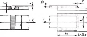
The strength of welded joints is increased by constructive (rational arrangement of seams relative to the acting forces, appropriate shape of seams) and technological (protection of the seam from harmful effects during welding, heat treatment, hardening treatment by cold plastic deformation) methods. Constructive methods for increasing strength are shown in Fig. 8.
Views 1–3 show the sequential strengthening of the flange welding unit loaded with torque by increasing the diameter of the circumferential weld. The shear resistance (proportional to the square of the connection diameter) in design 2 with the same seam cross-section is 7 times, and in design 3 it is 18 times greater than in design 1.
With the correct design of the seam, additional fastenings [on threads (type 4), interference fits (type 5), etc.] are unnecessary.
In centering joints, the parts to be welded are installed on landings with a gap of f8, f9, e8, e9, d9, d10. If more precise centering is necessary, h7, h8, h9 and transitional k7, k8 are used.
It is advisable to unload the welds, transferring the perception of loads to sections of the whole material and leaving only the function of connecting parts to the welds.
Some examples of unloading welds are shown in views 6, 7 (rod loaded with axial force) and views 8, 9 (thrust flange).
In the attachment of the cover to the shell of a cylindrical tank loaded with internal pressure (type 10), the welds of the cover and shell are subject to bending and shear by pressure forces. In the improved design 11, the shell weld is relieved by inserting the shell into the flange, and the bottom seam is relieved by clamping the bottom between the shell and bottom flanges.
Power seams should preferably be loaded in shear and tension, eliminating bending.
The design of a welded rod 12 loaded with a transverse force P is impractical. Force P, rotating the rod around point O, causes high tensile stresses in the area opposite to this point. In addition, the seam is subject to shear.
Design 13 is somewhat better, where the rod is centered in the socket of the part, due to which the seam is relieved from shear. However, the dangerous section of the rod is weakened by the weld.
In design 14, bending and shearing by force P are absorbed by intact sections of the rod that are not weakened by welding. The seam is practically unloaded from the action of force and serves only to fix the rod in the part.
It is advisable to unload the seam of the welded wall (type 15), bent by force P, by introducing a rib (type 16).
The bending of the butt seam (type 17) can be eliminated by introducing an overlay (type 18), the seams of which work primarily in tension. The butt seam in this design works in compression.
The butt joint of the corners (type 19) is not strong enough. It is more expedient to weld the corners along the plane of the shelves (type 20) with reinforcement (for difficult working conditions) with gussets (type 21).
It is advisable to weld the gussets not end-to-end (type 22), but overlapping (type 23).
It is recommended to position the welded ribs so that they work not in tension (type 24), but in compression (type 25), which almost completely relieves the load on the welds.
Views 26-29 show the sequential strengthening of a sheet joint loaded with a tensile force P and a bending moment Mizg. A comparison of the strength of various structures is given in table. 3.
The strength of the butt joint 26 is taken as one.
Welded sheets, overlays, gussets, etc. of large length and small thickness, it is advisable, in addition to welding along the contour, to be connected to the main part by spot welding (type 30) in order to avoid sheets falling behind when the system is deformed.
Slanted lap joint welds (type 31) subjected to tension experience additional shear loads along the weld line. In a balanced connection with a two-way bevel (type 32), the seams are relieved from shear.
Views 33-36 show the design of the channel welding unit. In connection with a channel located with flanges up (view 33), the upper sections of m vertical welds are subjected to high tensile stresses from the action of force P.
In a design with a channel located with flanges down (type 34), the force is absorbed by a horizontal seam n of great length; the weak end sections of vertical seams experience compression.
In the design with the connection of the channel into the tenon (type 35), the welds are unloaded from bending by force P; the bending moment is perceived by the flank seams and the transverse seam t experiencing shear. View 36 shows a connection reinforced with a gusset.
Eccentric application of forces that cause bending of the seam should be avoided.
Beaded seams in knots subjected to tension (type 37) experience bending. It is more expedient to design with a butt seam (type 38). In the unit for welding the bottom to a cylindrical tank with a flange (type Z9), the weld seam is subject to bending under the influence of internal pressure. The butt weld (type 40) experiences predominantly tension.
Avoid placing welds in high stress areas.
In welded beams subjected to bending, it is advisable to place the seams not at the flanges (type 41), but at the neutral section line (type 42), where the normal stresses are the smallest.
In connections subject to cyclic and dynamic loads, the location of welds should be avoided in areas of stress concentration, for example, in transitions from one section to another (View 43). Under these conditions, the seam is subjected to increased stress. In addition, stress concentration increases due to the heterogeneity of the weld structure.
An improved design is shown in view 44.
If it is impossible to move the seam beyond the stress concentration area, then it is recommended to use concave seams (type 45) with deep penetration, achieved by short arc welding.
The seam profile should be as symmetrical as possible with respect to the action of loads. In T-joints subject to tension (type 46), it is advisable to use double-sided seams (type 47). Lap joints (type 48) should, if possible, be replaced with butt joints (type 49). In butt joints, it is advisable to use double-sided edge preparation (type 51), since in joints with an asymmetrical seam (type 50) the force flow is bent, accompanied by stress concentration.
The fatigue resistance of welds can be significantly increased by mechanical processing, giving the seam a rational shape that reduces stress concentration.
It is advisable to process fillet welds along the radius with a smooth transition to the surface of the parts being connected (view 52). Butt seams are processed flush with the surface of the product, removing beads (reinforcements) both from the side of the main seam and from the side of the weld (type 53).
To smoothly connect the seam to the walls of the product, in most cases it is necessary to trim the walls simultaneously with processing the seam (dashed lines in views 52, 53), for which allowances (c) should be provided for processing.
In Fig. Figure 9 shows the fatigue curves of a butt joint with “reinforcements” (lower curves) and after their removal by mechanical processing (upper curves). Thin lines are fatigue curves for the connection without heat treatment, thick lines are after stabilizing heat treatment (annealing at 670°C). As can be seen from the graph, removing the “reinforcements” increases the cyclic strength by approximately 2 times, and heat treatment by 15-20%.
The cyclic strength is significantly increased (by 30-40%) by smoothing the welds with a tungsten electrode in an argon atmosphere.
Strengthening the seams by plastic deformation in a cold state (rolling, shot peening, embossing with a pneumatic tool with beam stampings) makes it possible to bring the fatigue resistance of the seam to the strength of the base metal.
Weld reinforcement technology
The very principle of intensifying welding is not difficult to understand; it will be carried out by gradual and layer-by-layer surfacing, where each layer will be approximately 2 mm in height. Processing begins from the most difficult places, that is, in those areas where there are any defects - craters, undercuts, sagging.
For electrodes that will be used in the process, there is a GOST standard, which requires a diameter of 4 mm.
Each layer is processed only after the previous one has cooled to 100 °C. Gradually, the welding trace lengthens, then expands a little, thanks to this a reinforcing effect is obtained.
It is important to remember about exceeding the working heights of the legs, which must be avoided, and also not to reinforce the transverse components under load.
This can lead to damage to the entire welded joint, and therefore the entire structure where it was used.
Speaking about the legs of the connections, here after fusing the reinforcing layer, the height of the leg itself should be less than the thickness of the flange from the side of the feather, and also less than the thickness of the profile flange when viewed from the side of the butt. In the second case, the height of the leg should not just be less than the thickness, but less than one and a half thicknesses.
Corner profile processing is carried out only in the direction that was initially chosen. It is not recommended to change it, as it can create excessive stress at the connection point.
Reinforcement of butt seams
Strengthening butt welding is complicated by the fact that most often its strengthening can lead to damage to the joint. For example, if the butt seam is made along the entire length or height of the metal components, then no reinforcement can be done at all. Surfacing will create excessive concentration at the melting point, due to which the surfacing can not only deteriorate, but also completely collapse. The thing is that the height of such welds is determined only by the elements being joined and taking into account the structure of the bead of the connection itself. This roller is the protrusion.
If the butt welding still needs to be processed, then you first need to relieve the tension with abrasive tools. After this, the area of the overlays is calculated, with the help of which the seam will be strengthened.
Reinforcement of corner seams
Here, strengthening of welded joints will be carried out by increasing the length or thickness of welded deposits. The first option is used more often, since it is better to increase the area and distribute the stress over it, rather than concentrate it.
The length and thickness of the created welds, as well as the thickness of the reinforcing layer itself, are calculated mathematically. Thus, they can be determined by the difference between the design force in the welded joint and the load-bearing capacity of this weld. It is important to take into account here that the design force will always be affected by its displacement relative to the center of gravity of the element’s section.
All formulas, symbols for them and tables with suitable values are in GOSTs, therefore in most cases everything can be calculated with maximum accuracy. And the accuracy of the calculations will make it possible to more accurately strengthen the welds.
Sometimes strengthening of welded corner joints occurs with the introduction of additional parts, but this is not necessary. This method will only be justified if there is room to add new layers. Basically, standard welding equipment with electrodes correctly selected in diameter is used.
If you increase the connections by increasing their length, then the load on the welded fasteners should not exceed the design resistance. Thus, the strength of the deposits will increase in proportion to the increase in the length and thickness of the connection.
This method is suitable for any fillet welds, except transverse ones.
Also, in order to make the welded area longer, gussets can be used, which are welded to the main elements using butt welded joints.
It is important to be careful when forming the back side of the seam, since if the heat supply is uneven, lack of penetration will appear, which will negatively affect the characteristics of the part.
But the main defect that appears in such situations is called “excess convexity,” that is, excess deposited metal on the face of the materials. This excess of convexity occurs most often due to non-compliance with the welding technique itself and the high feed speed of the filler wire. It can be corrected by sanding or rolling with rollers.
Making a perfect weld is an impossible task, but you can always strive for it. Therefore, you need to not only have good welding skills, but also understand the small but important nuances of the welding process. This is precisely the ability to make a high-quality strengthening of an already made connection.
Strengthening connections of metal structures
REINFORCING METAL STRUCTURES
General provisions
Strengthening of metal structures can be done after they have been unloaded or under load:
– increasing the cross-section of individual elements and their connections,
– changing the design diagram of structures
.
A special feature of strengthening metal structures is the availability of the cross-section
along the entire length of the elements and
the weldability
of the metal, allowing to reduce the labor intensity of ensuring the joint operation of the main and additional elements.
However, heating the elements during welding can reduce its strength. At a temperature of more than 550°C, the metal goes into a plastic state and is switched off from the work of absorbing forces. The degree of reduction in the strength of the metal at the welding site depends on the welding method and mode, the thickness and width of the element, as well as on the direction of the welds. Thus, for longitudinal seams the reduction in strength is up to 15%, and for transverse seams it reaches 40%. Based on this, the use of transverse welds when reinforcing metal structures under load is prohibited.
For the purpose of safety of work and increasing the efficiency of strengthening metal elements and their interfaces, one should strive to maximize the unloading of the structure before strengthening, so that the maximum stresses do not exceed (where is the design resistance of the steel according to the yield strength).
15.2.
Strengthening metal structures by increasing their cross-section
Strengthening metal structures working in tension and compression
and
bending
,
increasing the cross-section
of the elements is done by attaching additional elements.
The joint operation of additional reinforcement elements with the reinforced structure is ensured by welding
, as well as using
a bolted
or
riveted connection
.
When strengthening centrally stretched and compressed metal structures, one should strive to maintain alignment
reinforced elements and joints (that is, additional elements must be positioned so that the position of the center of gravity of the element does not change after strengthening), otherwise, the strength of the reinforced element and the joint must be checked, taking into account the resulting eccentricity.
When designing reinforcements, welds, bolted and riveted connections must be located in places convenient for execution and quality control. In addition, when welding joints, the appearance of additional and residual welding deformations should be taken into account. For example, strengthening of trusses should begin with the elements and nodes of the lower chord, and then strengthen the upper chord.
Ensuring that additional parts work together while reinforcing stretched ones
elements are made by their obligatory insertion into knots at a distance necessary to place attaching seams sufficient for full inclusion in the work at the border of the knot gusset.
As additional elements when strengthening centrally stretched elements, as a rule, strips and round rods are used (Fig. 15.1). In this case, in the case of welding reinforcing strips to the flanges and the feather of paired corners, it is necessary to cut off the protruding ends of the connecting strips.
In the case of ensuring the joint operation of additional elements with a reinforced tensile element by welding, it is recommended to make welds with a weld leg height of 3...6 mm (depending on the thickness of the parts being connected), and seams located near the edge of the element should be made continuous, because Intermittent seams create numerous “notches”—stress raisers that promote brittle tensile failure.
Strengthening compressed
steel structure elements are produced:
– an increase in the cross-section of the element with a slight change in its flexibility,
– an increase in the cross-section of the element with a significant decrease in its flexibility,
– reducing the design length of the element without changing the cross-section.
In the practice of strengthening metal structures, the first method is used for compressed elements of short length (short), when the strength of the element is determined by its cross-sectional area. Two other methods of strengthening are typical for long compressed elements that lose stability upon destruction.
In the first case, to strengthen centrally compressed elements, similarly to tensile ones, strips and round rods can be used as additional elements, effectively increasing the cross-sectional area, but slightly changing its bending rigidity (see Fig. 15.1). As in the case of tensile elements, additional reinforcement parts must be inserted into mating nodes.
When strengthening compressed elements by increasing the cross-section with decreasing its flexibility
as additional elements, rolled profiles are used in the form of pipes, angles, channels, etc., developing the cross-section and effectively increasing its bending rigidity (Fig. 15.2). Moreover, if there is no danger of loss of stability for the section of an unstrengthened element near the node, the reinforcement parts may not be inserted into the node or attached to it. It is allowed to use intermittent welds, which reduce welding deformations, reduce the time of welding work and the mass of deposited metal.
Rice. 15.1. Strengthening by increasing the cross-section without changing the flexibility of metal elements: a
– from paired corners;
b
– from paired channels;
in
– from I-beams
Rice. 15.2. Strengthening by increasing the cross-section with decreasing flexibility of metal elements: a
– from paired corners;
b
– from paired channels and I-beams;
c
– welded continuous section;
g
– riveted
Reducing the effective length
individual elements are effective when their stability is not ensured.
Strengthening of compressed elements by reducing its design length in the plane of the truss is done by installing additional braces or hangers (Fig. 15.3, a
), from the plane of the truss or for free-standing racks - prestressed trusses (Fig. 15.3,
b
,
c
).
Rice. 15.3. Strengthening steel structures by reducing their effective length:
A
– installation of additional braces;
b
,
c
– installation of prestressed trusses: 1 – reinforced element, 2 – additional braces, 3 – additional suspension, 4 – prestressed trusses
Strengthening bendable
metal structures has the following features:
— the increase in the cross-section of the bending element can be limited only to the zone of action of maximum bending moments, where reinforcement is required by calculation;
— when designing reinforcement, one should strive for the most efficient placement of additional parts (at the greatest possible distance from the neutral axis of the unreinforced section);
— taking into account the influence of welding deformations during reinforcement, which increase the deflection, strengthening of the bending elements must begin with the lower chord, then, if necessary, the wall should be strengthened, and lastly the upper chord.
Some options for structural schemes for strengthening steel beams are shown in Fig. 15.4 and 15.5.
Rice. 15.4. Strengthening a bending beam structure in a span
Rice. 15.5. Strengthening steel beams by increasing the cross section using:
A
– plates;
b
– rods;
in
– corners;
g
– pipes;
d
– I-beams
In addition to strength conditions, a reinforced steel beam must satisfy the conditions of general and local stability. Increasing the local stability of beams is achieved by installing additional transverse beams (Fig. 15.6, a
), longitudinal (Fig. 15.6,
b
) and diagonal stiffeners (Fig. 15.6,
c
).
In order to reduce the concentration of local stresses at the ends of short transverse stiffeners in the compressed zone, they should be bordered by longitudinal stiffeners (Fig. 15.6, d
).
Increasing the local stability of steel structure elements can also be achieved by concreting them (Fig. 15.7, a
) or by attaching wooden parts to them (Fig. 15.7,
b
,
c
).
Rice. 15.6. Strengthening the walls of steel beams with additional stiffeners:
A
– transverse;
b
– longitudinal;
c
– diagonal;
d
– short transverse ones bordered by longitudinal stiffeners
Rice. 15.7. Strengthening the walls of steel structures: a
– filling the column cavity with concrete;
b
,
c
– by attaching wooden beams; 1 – reinforced steel structure, 2 – concrete, 3 – hole in the wall for filling with concrete, 4 – wooden beams, 5 – coupling bolt
15.3.
Calculation of metal structures strengthened by increasing their cross-section
Calculation of strengthening of steel structures by increasing their cross-section is carried out based on the stage of the stress-strain state and the accepted hypothesis:
— by elastic stage
– the cross-section of the additional reinforcement element perceives only the force from the loads applied to the structure after the reinforcement;
— by plastic stage
– when the stresses in the cross-section of the reinforced element reach the yield point, the stresses are redistributed and equalized with the cross-section of the additional element.
A diagram of the stressed state of a metal beam reinforced under load is shown in Fig. 15.8.
Rice. 15.8. Diagram of the stress state of a beam reinforced under load:
A
– in the elastic stage;
b
– in the plastic stage
Calculation of reinforcement of metal structures at the plastic stage
gives more economical solutions, but is not experimentally confirmed for all cases of destruction.
Therefore, this calculation option is used under the action of static loads on reinforced elements in the absence of the danger of loss of stability. In other cases, the calculation is made according to the elastic stage
.
The calculation of reinforced centrally stretched and short compressed elements is carried out based on the strength conditions:
- according to the elastic stage
; (15.1)
- according to the plastic stage
, (15.2)
where is, respectively, the longitudinal force acting in the element during its strengthening and the longitudinal force from the additional load applied after strengthening; – cross-sectional area of the main and additional elements, respectively; – design resistance of the steel of the main element; – coefficient of operating conditions of a structural element according to [11, Appendix 4*].
Calculation of the strengthening of compressed elements according to the stability condition is carried out taking into account the fact that loss of stability of an element strengthened under load can only occur for the entire reinforced section. Therefore, the calculation uses the longitudinal bending coefficient, determined by the flexibility of the element after reinforcement.
The calculation of reinforced centrally compressed elements is carried out based on the condition of ensuring stability
. (15.3)
Possible distortions from welding when checking stability can be taken into account using the operating conditions coefficient.
Calculation of the strength of extremely compressed or stretched fibers of reinforced bending elements is made from the conditions:
- according to the elastic stage for the outermost fiber of the main section at a distance from the center of gravity of the main section and at a distance from the center of gravity of the reinforced section
; (15.4)
- according to the elastic stage for the outermost fiber of additional cross-section
; (15.5)
- according to the plastic stage
, (15.6)
where is, respectively, the bending moment acting in the element during its strengthening and the bending moment from the additional load applied after strengthening; – moment of inertia of the cross section of the element, respectively, before and after reinforcement; – design resistance of steel, respectively, of the main and additional element in tension or compression; — distance from the center of gravity of the reinforced section to the outermost fiber of the additional element; — plastic moment of resistance of the cross-section of a reinforced element, taken to be no more than 1.2 times the elastic moment of resistance of the cross-section of a reinforced element.
For reinforced bending elements, the condition of shear strength at the contact of the main and additional sections must be met
, (15.7)
where is the static moment of part of the cross-section of the additional reinforcement part relative to the neutral axis; – thickness of the main or additional element at the junction; – design resistance of steel to shearing of the main or additional element.
The local stability of the wall of beam structures after reinforcement is checked for all compartments between the transverse stiffeners without taking into account the initial stresses in it from the load during reinforcement according to the methodology of the current standards.
The seams attaching additional reinforcement parts to the main section of the reinforced elements are designed to withstand shear forces equal to the maximum tensile or compressive forces for the additional reinforcement parts.
Strengthening of individual elements of metal structures that have bents, cracks, dents and section breaks is carried out, as a rule, after unloading them by leveling, attaching additional parts (Fig. 15.9, 15.10.) or replacing the damaged part (Fig. 15.11).
Rice. 15.9. Reinforcement of damaged steel structure elements with linings: a
- from the corner;
b
– from a channel with additional connecting strips;
c
– from a plate
Rice. 15.10. Reinforcing curved steel elements with sprengel
Rice. 15.11. Restoration of elements of steel structures by cutting out and replacing the damaged part: a
– elements from paired corners;
b
– elements from a single corner
Strengthening connections of metal structures
Reinforcement of welds
produced by
increasing their length
or
thickness
.
Butt welds are not reinforced, since their height is determined by the thickness of the elements being joined and the construction of a weld bead protruding from the surface of the elements can only worsen its operating conditions due to the concentration of local stresses.
Fillet welds are strengthened by increasing their length (by installing additional front seams or welding additional ribs, overlays, etc.) and (or) leg. At the same time, in order to reduce the influence of welding stresses, the distance between the elements of the mating units is recommended to be at least 40 mm (Fig. 15.12, 15.13, a
,
b
).
Rice. 15.12. Reinforcement of welds: a
– increasing the length due to the application of a frontal seam;
b
– increasing the height of the legs of fillet welds: 1 – existing welds, 2 – additional frontal weld, 3 – additional surfacing
Increasing the thickness of the seam must be done layer by layer, fusing a layer of no more than 2 mm, starting from the place of the defect of the seam being reinforced (undercuts, craters, sagging, etc.) and using electrodes no more than 4 mm thick. Reinforcement of the subsequent seam is performed after the previous one has cooled to 100°C. The height of the weld leg after fusing should not exceed: the thickness of the flange on the side of the feather, one and a half thickness of the profile flange on the butt side.
Reinforcing transverse seams of tensile elements under load is not allowed.
When increasing the length of the welds of the joined corner profile elements, additional seams should be applied in the direction of the existing ones, starting from the edge of the gusset from the side of the butt.
| 22-2 |
Calculation of reinforced welds
is carried out without taking into account the initial stresses from the load during amplification.
Rice. 15.13. Strengthening nodal connections: a
,
b
– welded;
c
– riveted: 1 – additional seams, 2 – linings, 3 – additional gussets, 4 – additional ribs, 5 – additional high-strength bolts
Strengthening rivet and bolt connections
when the tie of the package of parts is weakened, it is done by increasing the number of rivets and bolts (Fig. 15.13,
c
) or replacing them with high-strength bolts with prestress by tightening the nuts with calibration wrenches. The tension of high-strength bolts is carried out from the middle of the assembly to the edges. In some cases, strengthening of rivet and bolted connections is carried out by replacing them with welding.
Calculation of high-strength bolts and welds
reinforced rivet and bolt connections, combining rivets ("black" bolts) and high-strength bolts (welds) after reinforcement, due to different deformability, the full force is produced after reinforcement.
15. 1 5. Strengthening metal structures
by changing their design scheme
Strengthening metal structures by changing their design scheme is an effective method that allows you to redistribute forces between elements. All methods discussed for reinforced concrete structures (topic 12) ( changing the location of load transfer
, increasing the degree of external static indetermination, increasing the degree of their internal static indetermination) are also applicable for metal structures.
In Fig. 15.14 – 15.16 shows schemes for strengthening metal structures by increasing the degree of static indetermination
: by
ensuring the continuity of
steel hinged beams (Fig. 15.14), by installing
additional rigid and elastic supports
in the form of
struts
,
hangers
and
brackets
for beam structures (Fig. 15.15), by installing
tightening rods
,
hinge-rod chains
for trusses (Fig. 15.16,
a
,
b
),
including
the design of a light-aeration lantern in joint work with the truss (Fig. 15.16,
c
).
Rice. 15.14. Strengthening steel beams to ensure their continuity:
1 – steel linings
When designing reinforcement of structures by changing their design scheme, the strength and stability of all elements and their connections should be checked under the action of changed forces. The use of these strengthening methods may entail the need to strengthen not only individual elements, but also node connections.
You should strive for maximum unloading of reinforced structures, since only the forces from the load applied after strengthening will be redistributed according to the new scheme. Effectively prestress additional reinforcement elements.
Rice. 15.15. Schemes for strengthening steel beams with additional rigid and elastic supports: a
– pre-stressed struts supported on foundations;
b
– struts supported on a column;
c
– pendants;
d
– prestressed brackets: 1 – struts, 2 – tightening with tension device, 3 – hangers, 4 – brackets
Rice. 15.16. Schemes for strengthening trusses: a
– pre-stressed tightening,
b
– hinge-rod chains,
c
– inclusion of the lantern structure in joint work with the truss: 1 – tightening, 2 – tension device, 3 – steel rope, 4 – suspension, 5 – additional stand, 6 – additional brace
In Fig. 15.17 shows examples of strengthening steel beam structures by increasing the degree of internal static indetermination using prestressed horizontal and truss tightening devices.
Rice. 15.17. Schemes for strengthening steel beams by increasing the degree of internal static indetermination: a
– pre-stressed horizontal tightening;
b
– prestressed truss tightening: 1 – horizontal tightening, 2 – tension device, 3 – anchor device, 4 – truss tightening, 5 – additional stand, 6 – additional strut
In this case, the anchor devices at the ends of the tie can be placed anywhere along the span of the reinforced structure. The principles for calculating steel beam elements reinforced with prestressed ties are no different from the calculation of reinforced concrete elements. The calculation of the joints between the tightening and the reinforced element is carried out for the action of forces in the tightening in the limit state according to the current regulatory documents for steel structures.
Strengthening the weld seam!
- Log in to reply to this topic
#1 angelhranytel
Good day to all welding specialists!
A question ! Many will find it funny!
How does the strengthening of the weld seam affect the strength characteristics of the seam? For example, we mean a butt joint of sheet steel! If you clean the seam flush, the strength of the seam will change? Or what other characteristics? It is advisable to hear the answers not of dreamers and theorists, but of people who conducted similar physical and mechanical tests in the laboratory! There is a rupture, torsion, compression, etc. If you have documented arguments, please send them! Thank you all for your understanding!
Remove weld reinforcement, what is it?
Unified system of design documentation
CONVENTIONAL IMAGES AND DESIGNATIONS OF WELDED JOINTS
Unified system for design documentation. Symbolic designs and representations of welds and welded joints
Date of introduction 1973-01-01
By Resolution of the State Committee of Standards of the Council of Ministers of the USSR dated May 10, 1972 N 935, the introduction date was set from 01/01/73
EDITION (July 2010) with Amendment No. 1, approved in July 1991 (IUS 10-91)
This standard establishes conventional images and designations of seams of welded joints in design documents of products from all industries, as well as in construction documentation that does not use images and designations used in construction.
Symbols for seams with different orientations of the two parts being welded and different bevels of the edges
Table 10
| General type of seam and edge used | Illustration of a seam and a symbol to indicate a connection |
| With flange | |
| Without bevel | |
| With one-sided bevel | |
| With one-sided bevel of one edge (HV) | |
| With one-sided bevel on both sides (Y) | |
| With one side bevel on one side (HY) | |
| With a one-sided curved bevel on both sides (U - seam) | |
| With one-sided broken bevel on both sides | |
| Podvarochny |
The correct designation indicated in the design documentation is the key to high-quality work of process engineers and welding specialists, because only through the correct display of symbols will they be able to embody the designer’s idea in metal in the drawing.
IMAGE OF WELDED JOINTS
1.1. The seam of a welded joint, regardless of the welding method, is conventionally depicted:
visible - with a solid main line (Fig. 1 a
,
V
);
invisible - dashed line (drawing 1 g
).
A visible single weld point, regardless of the welding method, is conventionally depicted with a “+” sign (Fig. 1 b
), which is done with solid lines (Fig. 2).
Invisible single points are not depicted.
A leader line is drawn from the image of a seam or a single point, ending with a one-way arrow (see Figure 1). It is preferable to draw the leader line from the image of the visible seam.
1.2. It is allowed to draw the contours of individual passes onto the image of the cross-section of a multi-pass weld, and they must be designated in capital letters of the Russian alphabet (Fig. 3).
weld reinforcement
3.1.23 weld reinforcement:
The convexity of a weld, determined by the distance between the base metal and the surface of the weld, measured at the point of greatest convexity.
3.2 The following abbreviations are used in this standard:
ZRA - shut-off and control valves;
HAZ—heat-affected zone;
KSS - control welded joint; NAKS - National Association of Inspection and Welding;
RTF - disposable crucible mold;
SASv - welding production certification system;
SDT - pipeline connecting parts;
TU - technical conditions;
UShS is a universal welding template.
3.3 This standard uses the following designations for welding methods:
AADP - automatic welding with a consumable electrode in an environment of inert gases and mixtures;
APG - automatic welding with consumable electrode in active gases and mixtures;
API - automatic welding with flux-cored wire in inert gases and mixtures;
AF - automatic submerged arc welding;
MP - mechanized welding with a consumable electrode in active gases and mixtures;
MPS - mechanized welding with self-shielding flux-cored wire;
RD - manual arc welding with coated electrodes.
3.1.61 weld reinforcement:
Weld convexity, determined by the distance between the plane passing through the visible boundary lines of the weld with the base metal, and the surface of the weld, measured at the point of greatest convexity.
Dictionary-reference book of terms of normative and technical documentation. academic.ru. 2015.
- strengthening the foundation
- Butt weld reinforcement
See what “weld reinforcement” is in other dictionaries:
strengthening - 3.18 strengthening: A set of measures that ensures an increase in the load-bearing capacity and operational properties of a building structure or a building and structure as a whole, including foundation soils, compared to the actual state or design... ... Dictionary of terms of normative and technical documentation
Surface reinforcement - Face reinforcement Surface reinforcement. Reinforcement of the weld on the side where the weld was made. (Source: “Metals and alloys. Directory.” Edited by Yu.P. Solntsev; NPO Professional, NPO Mir and Family; St. Petersburg, 2003) ... Dictionary of metallurgical terms
Welded joints and their designations
The relative position of the parts to be welded. Classification of compounds
Table 4
| Types of connections | Image |
| Butt joint (C) | the workpieces are adjacent to each other with their end surfaces and are in the same plane |
| Corner connection (U) | at which the angle of contact between the edges is more than 30° between the surfaces of the parts being connected |
| T-joint (T) | in which the parts are mated at an angle of 90 degrees |
| Lap joint (H) | in which the parts partially overlap one another and are parallel to each other |
| Slotted connection | a slot is made in the workpieces and one part fits into the other |
| Connections with electric rivets | used for making corner, butt, lap and T-joints |
Shape of the outer surface of the welds
The shape of the weld affects:
- physical and mechanical properties of the connection;
- consumption of electrode metal.
Convex seams almost always require additional processing - removal of the convexity mechanically (mill, abrasive wheels).
Welding seams, as well as defects in welded joints, are distinguished by the shape of the outer surface.
Table 5
| Types of seams | Illustration | Symbol | Characteristics |
| Normal(flat) | Economical. Work well under load. | ||
| Concave | Economical. Work well under dynamic loads. | ||
| Convex | The influx of convex metal is not economical. |
Various types of edge removal
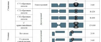
Depending on the thickness of the metal, the edges can be made at different angles and from different sides. The following types are distinguished:
- At right angles:
- for steel sheets with a thickness of 4 to 8 mm;
- for one-sided welding for metals up to 3 mm thick;
- for double-sided welding for metals up to 8 mm thick.
- V-shaped (with one-sided bevel), if the metal thickness is from 4 to 26 mm.
- X-shaped (with a double-sided bevel) if the sheets have a thickness of 12 to 40 mm.
- At an acute angle, reduced from 60° to 45° if sheets are more than 20 mm thick.
For good welding, a gap of 4 mm is left between the edges.
Graphic symbols of seam types for various connections
According to the method of performing the welded joint, they are distinguished:
- One-sided welding. This welding for butt joints is performed with edge penetration on the backing, or on weight.
- Double-sided welding. Welding of the second side is carried out only after thorough stripping (removal of the root) by mechanical surfacing of the first side to be welded. Most often, ceiling welding is performed in this way.
- Single layer welding.
- Multilayer welding. To reduce the heat-affected zone or when welding metals of large thickness, welding is performed in a similar way.
Welds of butt joints (shape, designation, example)
Table 6
| Character of the seam | V-shaped | ||
| Without bevel | From beveled edge | With two beveled edges | With two symmetrical bevels of two edges |
| Unilateral | |||
| Bilateral | |||
| Single-sidedwith gasket |
Corner joint seams (shape, designation, example)
Table 7
| Character of the seam | Without bevel |
| Unilateral | |
| Bilateral | |
| One-sided end-to-end | |
| Double-sided end-to-end |
T-joint seams (shape, designation, example)
Table 8
| Character of the seam | Without bevel |
| Bilateral | |
| Double-sided chess |
Lap joint seams (shape, designation, example)
Table 9
| Character of the seam | Without bevel |
| Bilateral | |
| Single-sided intermittent |
According to international standards (ESKD), welds of flat sheets of metal and pipes are classified according to spatial position into:
- horizontal;
- vertical;
- ceiling;
- welded in the lower position.
Depending on this location, it is advisable to use different types of edge removal. Under conditions of careful preparation, namely cleaning, proper adjustment of the edges (blunting the edges - prevents burn-through and leakage of metal, parallelism of the edges - guarantees a uniform seam), the following advantages of the weld can be achieved:
- Economical. Minimum metal consumption for welding.
- Welding speed efficiency. Such edges provide the shortest amount of time for welding in one approach.
- Strength. It is possible to achieve a strength of the welded joint that is not inferior to the strength of the base metal.
Therefore, the technical documentation must necessarily indicate: the type of seam and the type of edge to be removed, which will give the best result when welding the seam.
Radiographic inspection of welds is one of the most effective and common methods for inspecting joints. Do you want to decorate your home very well? This can be done using metal furniture. Read more about this here.
Do you need to thoroughly clean metal? An effective method is described at https://elsvarkin.ru/obrabotka-metalla/peskostrujnaya-ochistka-metalla-i-oborudovannie-priminyaemoe-dlya-dannyx-rabot/ link.
IMAGE OF WELDED JOINTS
visible - with a solid main line (Fig. 1 a, c);
invisible - with a dashed line (Fig. 1 d).
A visible single weld point, regardless of the welding method, is conventionally depicted with a “+” sign (Fig. 1 b), which is made with solid lines (Fig. 2).
Invisible single points are not depicted.
From the image of a seam or a single point, draw a leader line ending with a one-way arrow (see drawing 1). It is preferable to draw the leader line from the image of the visible seam.
The boundaries of the seam are shown as solid main lines, and the structural elements of the edges within the boundaries of the seam are shown as solid thin lines.
Weld designation structure
Symbol for visible and invisible seams
- above the shelf - visible;
- under peace - invisible.
Designations of types of welding:
- electric arc - E,
- gas - G,
- contact - Kt,
- in a protective gas environment - 3.
Symbol of weld seam:
According to the picture:
- No. 1 - Designation of the standard for the types and structural elements of welded joints.
- No. 2 - Alphanumeric designation, GOST.
- No. 3 - Standard or type, conventional graphic sign.
- No. 4 - The size of the seams in section, the length of the leg.
- No. 5 - Fillet weld sign indicating the length of the section.
Table 1
| Sign | Meaning of the sign | Sign location |
| Intermittent seam, checkerboard seam | ||
| intermittent or point with chain arrangement |
- No. 6 - An auxiliary sign to indicate processing.
table 2
| Sign | Meaning of the sign | Sign location |
| on an open line | ||
| Process sagging and irregularities with a smooth transition to the base metal | ||
| Remove the bulge |
- No. 7 - Designation for an auxiliary seam.
Table 3
| Sign | Meaning of the sign | Sign location |
| over a closed line | ||
| performed during installation of the product |
The following requirements are put forward for all types of signs in the weld symbol:
- main and auxiliary signs are indicated by solid thin lines;
- signs must be the same height as the numbers included in the designations.