Assortment of equipment from tool
We offer a wide range of different accessories: cams, bushings, vices, collets, drill chucks and much more.
Each item is represented by several manufacturers and in the greatest possible variations. For example, there are two types of drill chuck - not only can you buy a traditional version, but also a self-locking drill chuck. In addition, it is possible to select a cartridge from various manufacturers. Vast many years of experience in the tool market allow us to best meet the needs of customers. , buy turning equipment, tme equipment.
Threading heads, threading chucks, mandrels for Optimum drilling machines
- Allows you to cut M5 - M12 threads.
- Four-speed clutch for transmitting torque.
- Built-in reverse mechanism when changing feed direction.
- Landing surface B16.
The threading head is designed for cutting threads in the range from M5 to M12 with taps. The threading head has an adjustable safety clutch, preventing breakage of the taps; upon reaching the maximum permissible forces, the head stops and it is enough to move the threading head back along the axis, and the reverse stroke is activated at double speed. Using the threading head,
spindle stroke.
you can use the machine without reversing
M7
M12
M20
And
The clamping chuck contains a device for axial thread pitch compensation. The quick-change inserts are equipped with an overload protection device (to prevent breakage of the tap). Complete set: Threading chuck KM2, d 19mm Safety heads d 19mm, for taps: M3, M4, M5, M6, M8, M10, M12. Head wrench.
| M5- | M8- | ||
| Cutting thread range | 2-7mm | ||
| Morse mandrels included | 2 and 3 | ||
| cone modification | paw | paw | paw |
| vendor code | 335 2043 | ||
| Price, rub. | 22 643 | ||
| Availability | |||
| stock | stock | stock | |
| Model | K2L-3-12 | K3L-3-12 | K3L-12-24 |
| Thread range | M3-M12 | M3-M12 | M12-M24 |
| Chuck shank | KM2 presser foot | KM3 presser foot | KM3 presser foot |
| Collets |
included
| 7pcs | 7pcs | 7pcs | |
| vendor code | P30205 | P40206 | P50207 |
| Price, rub. | 18 440 | 18 287 | 25 487 |
| Availability | in stock | in stock | in stock |
| Model | K4L-3-12 | K4L-12-24 |
| Thread range | M3-M12 | M12-M24 |
| Chuck shank | KM4 presser foot | KM4 presser foot |
| Collets |
included
TO TOP[]
THREADED CHUCK IN A SET
| 7pcs | 7pcs | |
| vendor code | P80534 | P60208 |
| Price, rub. | 18 520 | 25 487 |
| Availability | in stock | in stock |
| Model | K2-3-12 | K2-3-12 |
| Thread range | M3-M12 | M3-M12 |
| Chuck shank | KM2 | KM2 |
| Collets |
included
| 7pcs | 7pcs | |
| vendor code | P | P88150 |
| Price, rub. | 18 440 | 18 440 |
| Availability | in stock | in stock |
| Model | K3-12-24 | K4-12-24 |
| Thread range | M12-M24 | M12-M24 |
| Chuck shank | KM3 | KM4 |
| Collets |
included
TO TOP[]
THREADED CHUCK IN CNC KIT
Complete set: Threading chuck with cold-component 7:24-40BT (MAS 403), d 19mm Safety heads d 19mm, for taps: M3, M4, M5, M6, M8, M10, M12. Head wrench.
| 7pcs | 7pcs | |
| vendor code | P98159 | P09105 |
| Price, rub. | 18 642 | 25 487 |
| Availability | in stock | in stock |
| Model | BT40-3-12 | BT40-12-24 |
| Thread range | M3-M12 | M12-M24 |
| Chuck shank | 7:24-40(BT40) CNC | 7:24-40(BT40) CNC |
| Collets |
included
TO TOP[]
SAFETY THREADING HEAD
For taps
Used in conjunction with thread-cutting chucks. Designed for fastening right-hand taps in accordance with GOST 3266-81.
| 7pcs | 7pcs | ||||
| vendor code | P58105 | P68105 | |||
| price, rub. | 22 670 | 24 240 | |||
| Availability | in stock | in stock | |||
| M3 | M4 | M5 | M6 | M8 | |
| Chuck Ø mm. | 19 | 19 | 19 | 19 | 19 |
| vendor code | P 19105 | P 29105 | P 39105 | P 49105 | P 59105 |
| Price, rub. | 3 625 | 3 625 | 3 625 | 3 625 | 3 625 |
| Availability | |||||
| stock | stock | stock | stock | stock | |
| Tap | M10 | M12 | M14 | M16 | M20 |
| Chuck Ø mm. | 19 | 19 | 19 | 30 | 30 |
| vendor code | P 69105 | P 79105 | P 89105 | P 99105 | P 00205 |
| Price, rub. | 3 625 | 3 625 | 3 625 | 3 625 | 3 625 |
| Availability | stock | stock | stock | stock | stock |
Devices for fixing workpieces
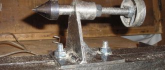
For fastening workpieces, universal devices are used - centers, bushings and mandrels. Centers are used for parts longer than three meters with base surfaces in the form of center holes. Depending on the design, they are divided into rotating and stationary, and are installed in the headstock and tailstock quills. The angle of the front center taper depends on the type of work. For normal operations it is 60°, for heavy work - 90°. The material is tool steel with a hardness of HRC 55-58.
There are various design options for centers to perform special operations:
- Grooved centers for processing hollow workpieces.
- Centers with undercut. Used for end cutting.
- Spring-loaded or “floating” centers – for precise installation of parts along the end.
The figure above shows the designs of the centers: a - ordinary; b - corrugated; c - with recess, d - rotating for workpieces with central recesses; d - rotating for workpieces with conical ends.
In the event that a part cannot be fixed in the chuck, for example due to an irregular geometric shape, a special device is used for securing workpieces on machines - a faceplate. This is a flat disk with radial or concentric grooves, which is attached to the machine spindle through a flange. The grooves can have a T-shaped or figured shape in cross section. The workpiece is centered and fixed on the faceplates using replaceable clamps and adjustments.
For turning some workpieces with internal through holes, fixation using a mandrel is used. These devices are divided into center and spindle. In turn, center ones are divided into solid and expanding.
The figure above shows the mandrels in section: a - center; b - spindle; 1 - rod; 2 - workpiece; 3 - split element; 4 - nut.
Design Features
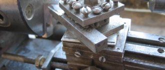
Grinding heads are a special design that is used to significantly expand the capabilities of a turning group machine. This mechanism conventionally refers to equipment. Design features include:
- the presence of its own electric motor, the power of which can be from 1 kW or more. This point determines that the head can become equipment for various models of lathes. as a rule, turning equipment has a closed gearbox and does not have a separate drive for connecting the equipment in question;
- the installed electric motor is connected to the lathe circuit, which determines the versatility of the entire structure. there is also a three-phase plug for inclusion in a separate power circuit;
- the head has its own frame, which, during modernization, can be rigidly attached instead of a standard tool holder. This point determines that the equipment makes it possible to obtain high-quality surfaces with high mechanization of the process. steel is used in the manufacture of the frame, which helps prevent vibration during operation by increasing the rigidity of the structure;
- rotation is transmitted using a belt drive to reduce speed.
The design is quite simple
When considering it, it is worth paying attention to the type of frame. This is due to the fact that only a certain type of bed can be used instead of a tool holder for a certain model of lathe
Grinding head for grinding the inner diameter of the workpiece
Grinding head for grinding the outer diameter of the workpiece
Repair of lathe bed guides
Bed guides are restored during repairs in various ways, for example by planing, milling, grinding, broaching, scraping. At some factories, surface hardening of the bed guides is carried out by rolling with a roller, as well as by hardening the solid. hours, which significantly increases the wear resistance of surfaces.
The choice of repair method depends on the degree of wear and hardness of the frame guides, the equipment of the repair base with special machines and devices, etc.
The most common methods for repairing bed guides are scraping, sanding and planing.
Repairing guides by scraping, even with wear of 0.05 mm, is very labor-intensive and expensive, so this process should be mechanized, and this has a great economic effect.
Repairing guides by grinding ensures high accuracy and cleanliness of processing; this method is practically indispensable when repairing hardened guide frames. Labor productivity during grinding is several times higher compared to scraping. However, when repairing unhardened machine guides, preference should be given to finishing planing. At the same time, high productivity is achieved, V6 surface cleanliness and accuracy are ensured in accordance with specifications.
Repair of bed guides by scraping
Rice. 48. Aligning the bed of a screw-cutting lathe on a stand
- Bridge base
- Threaded column
- Level
- Support
- Threaded column
- Level platform
- Threaded column
- Support
- Thrust bearings
- Level
- Frame level
- Balochka
- Surface of the frame for attaching the feed box
This technological process is characterized by the fact that the bed (installed on a stand or on a rigid foundation) is aligned in the transverse direction along the surface for attaching the feed box 13 (Fig. 48) using the frame level 11. This makes it possible to easily determine and install the caliper during repair perpendicularity of the surfaces for attaching the apron on the caliper carriage to the surface for attaching the feed box to the frame.
The horizontality of the guides in the longitudinal direction is determined in the usual way according to level 10.
Another feature of the typical technological process under consideration is that instead of the wearing surfaces of the guides under the tailstock (on the bed), usually taken as the base, in this case the surfaces for fastening the gear rack are taken as the base, and only sections (200-300 mm each) these surfaces at both ends of the bed. These surfaces never wear out and are in the same plane as the surfaces for attaching the feed box and the drive shaft bracket. Restoring the parallelism of the bed guides to the specified surfaces reduces the complexity of aligning the parallelism of the axes of the lead screw and the lead shaft to the bed guides.
Repair of guide frames using this technology, introduced in the LOMO repair service, comes down to the following operations:
1. Install the frame on a stand or a rigid foundation at a level using wedges and shoes. In the longitudinal direction, the check must be carried out at level 10 (Fig. 48), in the transverse direction - at the frame level applied to plane 13.
The curvature of the guides is checked at level 4, installed on the universal device 3, moved along the guides, or on the tailstock bridge.
Deviations from horizontality of the guides in the longitudinal direction are allowed no more than 0.02 mm over a length of 1000 mm.
The curvature of the guides is allowed no more than 0.02–0.04 mm over a length of 1000 mm.
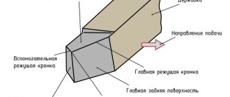
Rice. 49. Profile of the guides of the bed of a screw-cutting lathe 1k62
Plane 9 (Fig. 49) for attaching the feed box must be located vertically. A deviation of no more than 0.04-0.05 mm over a length of 1000 mm is allowed.
2. Scrape surfaces 3, 4 and 5 along a straight edge for paint. During the scraping process, the curvature of these guides and the parallelism of their surfaces 9 and 10 are periodically checked using a device, level and indicator (check method - see Fig. 10, b).
Non-straightness (towards convexity) is allowed no more than 0.02 mm over a length of 1000 mm. Curvature - no more than 0.02 mm per 1000 mm. Non-parallelism 1 to the base surfaces - no more than 0.06 mm along the length of the guides. The number of paint prints is at least 10 on an area of 25x25 mm.
3. Scrape guides 1, 2 and 6 along a straight edge for paint. Periodically check the parallelism of their surfaces 3, 4 and 5, the deviation of which should be no more than 0.02 mm at a length of 1000 mm and no more than 0.05 mm at a length of 3000 mm.
Spiral tortuosity is allowed no more than 0.02 mm over a length of 1000 mm. The number of paint prints must be at least 10 on an area of 25 x 25 mm.
4. Scrape surfaces 7 and 11 using a straight edge for paint. Periodically check the parallelism of their surfaces 1, 2 and 6 using a device with an indicator. Non-parallelism of no more than 0.02 mm along the length of the guides is allowed.
The final adjustment of surfaces 7 and 11 is made along the caliper carriage along with the clamping strips.
Repair of bed guides by grinding
This technological process consists of the following operations:
1. File and clean all protruding nicks and burrs on the surface 8 of the frame (Fig. 49).
2. Install the frame on the table of the longitudinal planing machine with surface 8, while placing 0.1 mm thick foil under the outer four corners between the supporting planes of the frame and the table surface. The frame is secured at the internal corners (shown by arrows in Fig. 50) and it is verified to be parallel to the movement of the table along surfaces 10 and 9 (Fig. 49) with an accuracy of 0.05 mm over the entire length of the surface.
3. Check the crookedness of guides 3, 4 and 5 using a level placed on the tailstock bridge or a special device (see Fig. 9).
Rice. 50. Scheme of deformation of the bed of a screw-cutting lathe
4. Secure the bed to the machine table with screws and pads, while simultaneously deflecting the bed by 0.05 mm. As practice shows, the accuracy of machining of guides is negatively affected by the non-straightness of the table of the planing machine on which grinding is performed. Deformation of the bed, which occurs both during installation and fastening on the machine table, and during processing, also increases non-straightness. Due to these shortcomings, the guide frames, after processing, turn out to be not only non-straightforward (toward concavity), but also twisted. Therefore, installation and fastening of the bed on the planer table are important points and require a careful and skillful approach to them. The bed should be fixed on the planing machine table so that the stands with their supporting surface are in closer contact with the surface of the table.
5. Additionally, check the crookedness of the guides. The readings should be the same as when checking before fastening. If the readings do not match, the screws are loosened and the frame is secured again so that the torsion data is the same as the data obtained before the frame was secured to the machine table.
6. Grind sequentially surfaces 3, 6, 11, 7, 2, 5, 1 and 4 (Fig. 49). Grinding is carried out with the end of a cup-shaped wheel, grain size KCh46 or K346 and hardness SM1K. Preliminary grinding is carried out with the spindle axis tilted relative to the direction of table movement by 1-3°.
The final grinding is carried out with the spindle axis perpendicular to the surface being ground. Grinding mode: feed 6-8 m/min, speed - 35-40 m/sec. Heating the surfaces being processed during grinding is not allowed.
A typical technological process for repairing frame guides by grinding is presented in Table. 3. This technological process can also be used when grinding guides hardened by TV. h. However, you must first complete all the operations indicated on page 72.
Requirement for grinding heads
The production of rotating bodies on lathes has been carried out over the past several decades. As a rule, grinding was carried out using other equipment. This moment was determined by the following technological process:
- performing rough turning to remove a large layer of metal;
- performing fine turning to prepare the part for the finishing stage of the technological process;
- finishing on a cylindrical grinding machine.
Such a technological process determines an increase in costs due to the installation of a special machine for finishing processing. When creating a large batch of products, purchasing a grinding machine pays off, but in small-scale production, its purchase will lead to an increase in the cost of one product. A way out of the situation is the use of special grinding heads, which can also be used to obtain a surface with a high roughness class.
Design Features
Grinding heads are a special design that is used to significantly expand the capabilities of a turning group machine. This mechanism conventionally refers to equipment. Design features include:
- the presence of its own electric motor, the power of which can be from 1 kW or more. This point determines that the head can become equipment for various models of lathes. as a rule, turning equipment has a closed gearbox and does not have a separate drive for connecting the equipment in question;
- the installed electric motor is connected to the lathe circuit, which determines the versatility of the entire structure. there is also a three-phase plug for inclusion in a separate power circuit;
- the head has its own frame, which, during modernization, can be rigidly attached instead of a standard tool holder. This point determines that the equipment makes it possible to obtain high-quality surfaces with high mechanization of the process. steel is used in the manufacture of the frame, which helps prevent vibration during operation by increasing the rigidity of the structure;
- rotation is transmitted using a belt drive to reduce speed.
The design is quite simple
When considering it, it is worth paying attention to the type of frame. This is due to the fact that only a certain type of bed can be used instead of a tool holder for a certain model of lathe
Installing the Lead Screw and Lead Shaft
This operation is excluded if the carriage repair is performed according to table. 5.
The alignment of the axes of the lead screw and the lead shaft, the feed box and the apron is carried out in accordance with the following standard technological process.
1. Install the feed box housing and secure it to the frame with screws and pins.
2. Install the carriage in the middle part of the frame and attach the rear clamping bar of the carriage with screws.
3. Install the apron and connect it to the carriage with screws (the apron may not be installed fully assembled).
4. in the holes of the feed box and apron for the lead screw or lead shaft. The ends of the mandrel must protrude by 100-200 mm and have the same diameter of the protruding part with a deviation of no more than 0.01 mm (play of the mandrels in the holes is unacceptable).
5. Move the carriage with the apron to the feed box until the ends of the mandrels touch and measure the amount of their misalignment (in the light) using a ruler and a feeler gauge.
6. Restore the alignment of the holes for the lead screw and the lead shaft in the feed box and apron by installing new linings, scraping the guides or carriage linings, and reinstalling the feed box.
Permissible deviation from the alignment of the feed box and apron holes: in the vertical plane - no more than 0.15 mm (the axis of the apron hole can only be higher than the feed box hole), in the horizontal plane - no more than 0.07 mm.
Reinstallation of the box height should be done when repairing carriage guides without compensating pads. In this case, the holes in the feed box for the screws securing it to the frame are milled. When moving the box horizontally, it is necessary to mill holes in the carriage for the apron fastening screws: the latter must also be shifted and then pinned again.
Scraping lathe guides
Restoring the geometry of lathe guides
Grinding the bed guides of a screw-cutting lathe
Grinding the bed guides of a screw-cutting lathe
Restoring a lathe bed