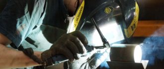
Welding technologies are used in the production of metal structures to connect various elements into a single, integral structure, device, machine. Welding technologies are diverse; the choice of a specific one depends on the size of the parts, the material used and the purpose pursued. Butt resistance welding is used when working with difficult-to-process products. It consists of welding metal components through uniform heating of the entire joint area. After this, the products are joined together with maximum force, which helps to obtain a strong, permanent seam.
Due to the rapid production of a welded joint, butt welding is characterized by high productivity. It is possible to obtain the required seam in the shortest possible time due to the rapid and uniform melting of the metal.
With this technology, there is no need to pre-prepare the edges. This allows you to significantly reduce financial and time costs. Compared to the other parts of the welded product, the butt seam is of equal strength. This means that installation can be carried out simpler, easier, and the resulting structure will be as reliable, safe and durable as possible.
Butt welding is characterized by the absence of the need to use high current. This is due to the ability of the consumable to provide a stable arc. And due to only local heating of the surface, it is possible to significantly increase the efficiency of the process and reduce electricity costs.
Content
- Definition, diagram and types of butt welding
- Resistance butt welding
- Flash butt welding
- The essence of the resistance butt welding process
- Heating the metal being welded
- Plastic deformation of metal
- Technological capabilities of butt welding
- Weldable materials and design requirements
- Preparation for welding
- Selecting welding mode parameters
- Treatment of joints after welding
- Welding machines
- Equipment control systems
- Devices and equipment
- Treatment of joints after welding
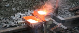
Resistance butt welding is a high-tech and, for the most part, automated method of joining parts. The share of flash butt welding is approximately 10% of all resistance welding used in practice. This welding method refers to electrothermodeformation processes, according to GOST 2601, but, unlike spot and seam resistance welding, the connection can be obtained using deep plastic deformation without melting the metal.
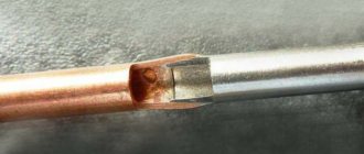
Oxidation problem
When working with metal, many people encounter the problem of oxidation. It is due to the fact that when heated, the material comes into contact with air, which leads to the procedure in question. When considering this technology, we note:
- The material becomes more susceptible to environmental influences.
- The quality of the resulting connection deteriorates.
The oxidation process also reduces the conductivity of some materials. It is worth considering that flash butt welding is often used to produce electrical equipment.
Definition, diagram and types of contact butt welding
Butt welding is a resistance welding method in which parts are welded over all areas of their contact. The resistance welding diagram is shown in the figure on the left. Parts pos. 1 are fixed in current-carrying clamps pos. 2, 3, one of which is movable and connected to the drive of force and movement of the machine. Based on the nature of heating, a distinction is made between flash butt welding and resistance welding.
Resistance butt welding
With this welding method, the parts are compressed with a fairly large force, about 3-5 kN. Then turn on the welding transformer, position 4, and either heat it with electric current to a high temperature (approximately 80-90% of the liquidus temperature), or melt the metal at the joint. Based on this, resistance butt welding can be divided into two more types - without local melting of the metal and with its melting.
After heating, the welding current is turned off and a force equal to the upsetting force is suddenly created, due to which either intense deformation of the solid metal occurs (squeezing the metal out of the joint), along with which the oxide films are removed, or the liquid metal and part of the heated solid metal are removed. In this case, physical contact is formed and a strong connection is formed. After welding, a thickening is formed on the parts - burr, pos. 5 in the diagram.
Flash butt welding
In butt welding, the parts are first supplied with a voltage within 6-8 V from the welding transformer. Then the parts are brought together until they touch with a small force of the order of several decanewtons. In certain areas of the contact, the current density is very high (up to 3-5 kA/mm2), as a result of which the metal at these points quickly heats up and melts with the formation of liquid metal bridges between the ends of the connected edges. Rapid overheating of these points occurs, and the metal in them melts with the formation of liquid metal bridges between the welded ends. Next, the jumpers quickly overheat and explode.
The ends continue to heat up due to the constant formation of new liquid bridges and their destruction, i.e. in essence, melting of the ends occurs. By the end of the process, a layer of liquid metal is formed on the entire surface of the ends. At this moment, the speed of approach increases sharply and the force increases. The ends of the liquid layer come into contact and most of the liquid metal, together with oxide films and part of the solid metal, is squeezed out of the joint with the formation of burr. During precipitation, the electrical current is switched off.
There are also cases of welding two joints at the same time, heating with high frequency currents, direct current and other types of contact butt welding.
The role of plastic deformation
Plastic deformation of the metal is caused by both external factors - force from the electrodes, and internal ones - stresses that arise during the unfree expansion of the metal in the welding zone. In spot, seam, projection and resistance butt welding, plastic deformation of the metal is present throughout the entire welding process: from the formation of cold contact to forging the joint. In flash welding, deformation occurs during the preheating and upsetting stages.
The main role of plastic deformation during spot, seam and projection welding is the formation of electrical contact, the formation of a plastic belt to keep the molten metal from splashing out and limit the spread of welding current in the internal contact, and to compact the metal at the cooling stage.
The primary role of plastic deformation in butt welding is to remove oxides to form metallic bonds at the joint (the second stage of the welding cycle) and electrical contacts (primarily during the first heating stage). Deformation is caused by the compression force generated by the welding machine drive. To form the initial electrical contact, a small pressure is sufficient, at which microplastic deformation of the surface topography of the ends occurs. To remove oxides and form bonds, a relatively large volumetric plastic deformation of the parts is required. In most cases, butt welding uses a free volumetric deformation scheme, in which the metal flows without any external restriction. In the butt welding process, the amount of deformation is judged by the shortening of parts caused by upsetting.
The essence of the resistance butt welding process
The main processes during butt welding are heating and plastic deformation of the welded edges. Thanks to these processes, oxide films are removed, physical contact is formed, and a connection is formed with the required mechanical properties.
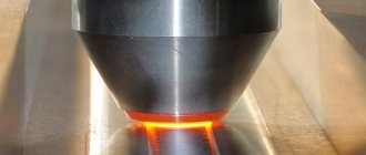
Heating the metal being welded
Heating is carried out in order to achieve a given temperature at the joint and warm up the heat-affected zone to a certain depth in order to achieve the required degree at the sediment stage. When resistance welding, the main share of thermal energy, about 85-90%, is spent on the resistance of parts, the thermal field is uniform. In the case of using long-term current pulses, heating of the heat-affected zone increases.
In flash butt welding, the temperature field is determined by the resistance level of the jumpers, which depends on their number and size. Therefore, the thermal field turns out to be uneven along the length of the parts, and in some cases, across the cross section.
One of the important parameters of the welding mode is the reflow rate. In most cases, the reflow rate is increased during the welding process to make the process more stable. When welding sections with an area of up to 100 cm2, it is recommended to preheat the parts. This promotes more uniform heating of the edges and accelerates the onset of edge melting.
Welding large sections is recommended to be welded with programmable control of current and melting speed or to use pulsed melting. During pulse surfacing, certain vibrations with a frequency of 3-45 Hz and an amplitude of 0.1-0.8 mm are superimposed on the main translational movement of the machine plate. Under the influence of these vibrations, the gap between the parts periodically changes, and the temperature in the heat-affected zone increases by 10-15%. At the same time, the reflow time and energy consumption are reduced by 3-4 times.
Plastic deformation of metal
The purpose of this operation is to create electrical contact at the initial stage. Deformation is ensured under the influence of a pressure of 5-10 MPa in resistance butt welding and about 1 kPa in flash welding. Also during this operation, oxide films are removed and physical contact is formed on a fairly large plane at the stage due to the movement of thin layers of molten metal along the joint. In this case, in the center of the connection the stress state is close to all-round compression, and closer to the surface, on the contrary, tensile stresses act.
Technological capabilities of contact butt welding
Butt resistance welding allows you to weld together all known structural metals, both homogeneous and dissimilar. The range of connected sections is from 1 mm2 to 20 dm2. Also, the parts to be connected can be of different assortments: wire, strips, various profiles, etc.
In resistance butt welding, the cross-section of parts is limited to 500 mm2 for steels, 200 mm2 for aluminum welding and copper welding.
The most widely used in practice is flash butt welding. Continuous reflow can be used to weld parts with a compact cross-section (rods up to 10 cm2, etc.) made of low-carbon steel and sheet parts and pipes with a slightly larger cross-section. Heated fusion welding is used for parts with a cross-section of 5-100 cm2; for large parts, fusion welding with programmable control of the current and the speed of movement of the clamps is recommended, and pulsed fusion allows you to weld parts made of steel with a cross-section of up to 20 dm2 or aluminum with a cross-section of up to 2.2 dm2.
The mechanical properties of welded joints obtained using flash butt welding are comparable to the mechanical properties of the base metal.
Seam properties
The spread of technology can be primarily associated with the high quality of the resulting seam. It is characterized by the following properties:
- Increased decorative qualities. During conventional welding, a wide shaft can be formed, which must be further processed to obtain a flat surface.
- Reliability and strength of connection. The seam can withstand a wide variety of impacts, including variable loads.
- In the area where the weld is located, the metal does not lose its properties, since local heating of the metal occurs.
As a rule, the quality of the resulting seam is checked visually. On a high-performance line, special equipment can be used for this.
Flash butt welding technology
Weldable materials and design requirements
In most cases, resistance butt welding is used for welding low-carbon steels, welding copper and aluminum wire. There are also positive results on welding pairs of dissimilar materials, such as copper with fechral, steel or cast iron with copper and aluminum. Such pairs of materials were welded using additional intermediate spacers, which additionally alloyed the weld.
Using flash butt welding, you can obtain high-quality connections between all structural metals, from welding aluminum alloys to welding heat-resistant steels and titanium alloys.
When preparing edges, the shape of the ends of the parts plays an important role, which should ensure uniform heating of the parts and the same degree of deformation during welding. Schemes for preparing parts for welding are presented in the figure above. The shape of the ends of the parts should protect them from oxidation and deformation; for this purpose, an annular protrusion is made during resistance welding, a sphere, or a cone (diagram b in the figure). The workpieces are installed in the conductive clamps of the welding machine. The dimensions of both ends should not differ by more than 15% in diameter and 10% in thickness.
Preparation for welding
To obtain a high-quality welded joint, the surfaces must be cleaned and given an even shape. To trim parts, mechanical cutting with scissors is used, sawed on machines or cut off with gas cutting. Additionally, the ends are processed with metal shot, etching, milling or grinding.
When resistance welding, the gap between parts should not exceed 0.5 mm, and when fusion welding - 15% of the fusion allowance. The installation length (l1+l2) when resistance welding strips of low-carbon steel with thickness S is 1.2S1/2, for alloy steel 1.1 S1/2.
When flash welding, l1+l2=homel+hoс+hк, where hк is the final distance between the clamps, which is determined experimentally, based on maintaining the stability of the parts and the low level of heat dissipation into the clamps.
Selecting welding mode parameters
The values of the mode parameters depend on the welding method and on the materials being welded. The main parameters of the resistance welding mode are:
Current density determined by the resistivity of the material. When welding steel it is 100-150 A/mm2, when welding aluminum 200-300, and when welding copper 400-500.
Welding time, which increases with increasing cross-sectional area of the part and decreases with increasing thermal conductivity of the material (welding of aluminum and copper). On average, the welding time for wire with a diameter of up to 5 mm is 0.2-1 s.
Upsetting pressure p, depending on the resistance of the heated metal to plastic deformation. For low-carbon steels, the upsetting pressure is approximately 20 MPa, for alloy steels 125 MPa, and for non-ferrous metals approximately 10 MPa.
For flash welding, the following basic parameters are determined:
Current density based on the full cross-section of the part. The current density increases with increasing cross-section of the part, or thermal and electrical conductivity. The value of this parameter is much less than for resistance welding and is 20 A/mm2 for steel, and 35 A/mm2 for aluminum and its alloys.
The melting rate vmelt and the amount of allowance hmelt are selected from the condition of uniform heating of the ends and sufficient heating of the heat-affected zone. Towards the end of the process, the reflow rate is increased. The higher the thermal conductivity of the metal, the greater the melting rate. When welding steels, it is, on average, 1-3 mm/s, chromium-nickel steels - 2.5-3 mm/s, aluminum and its alloys - 4-10 mm/s, and for copper and its alloys about 20 mm/s With.
The upsetting pressure p depends on the resistance to deformation and the degree of heating of the metal. For example, when welding low-carbon steels it is 70 MPa, corrosion steels 170, aluminum alloys 220, titanium and its alloys - 60 MPa. Allowance for upsetting under current hoc.t=0.4-0.7hos and increases with increasing cross-section of parts (hoc=5 mm, hoc.t=2 mm at S=10cm2 and hoc=11 mm, hoc.t=4 mm at S=100cm2.
Also an important parameter is the open-circuit voltage U, which is assigned the minimum required to ensure stable reflow.
Treatment of joints after welding
To obtain good mechanical properties, the joint is heat treated after welding. The most commonly used methods are normalization and vacation. Deburring from surfaces can be carried out in different ways, for example, with special scissors directly on a welding machine, on metal-cutting machines, or using cutter and plunger deburring tools. Inside straight pipes, deburring is carried out using broaches, and in bent pipes - with steel projectiles moved by compressed air, blowing the hot joint with oxygen, etc. Hail in large-diameter pipes is removed with rotating cutting heads.
Types of edge preparation
Butt joints can be made not only “on the fly”. For high quality and for large metal thicknesses, it is necessary to cut the edges.
Cutting is the removal of part of the cross section along the entire length of the future seam. The result can take several forms, which give the cutting option its name:
- straight - cutting is not performed, the edges remain in their original shape;
- V-shaped - the bevel is made even and throughout the entire thickness;
- X-shaped - 2 symmetrical bevels are made from the middle to each surface;
- curvilinear - the bevels form an irregular curved line that begins at any point in depth.
This shape can take either one edge or both. The selection of the type of cutting is also based on the direction of processing - one-sided and two-sided seams can be welded.
Metal is processed using manual means (macker, hammer and anvil) or mechanized ones (milling, chiselling, abrasive tools).
Useful article - How to properly weld metal with an inverter for beginners
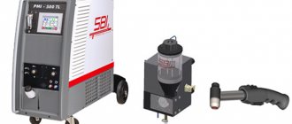
Equipment for resistance butt welding
Resistance butt welding machines
Machines for resistance butt welding are quite diverse in design and are classified according to the same criteria that are accepted for the classification of machines for spot and seam resistance welding. For example, they are also divided according to the type of welding. These are resistance and flash welding machines. They are also divided according to the type of current, their purpose and other characteristics.
The figure shows a diagram of a universal machine for resistance butt welding. The main components of the machine are the frame 8, welding transformer 9, secondary circuit 10, movable 4 and fixed 11 plates, conductive jaws 3 for clamping parts, clamping cylinders 1 and 2, feed drive 5, guides 6 and control system unit 7. In practice, more often All AC machines are used.
In addition, specialized machines are used to weld parts of a certain range. For example, there are machines specifically for welding band saws, for welding chains, and for welding railway rails, which can be performed both directly on the tracks and in stationary conditions.
Resistance welding of pipes with a diameter of no more than 1 m is carried out on stationary and mobile installations in the field. To weld large diameter pipes exceeding 1.4 m, special welding complexes with machines that are inserted into the pipe are used.
In instrument making and radio electronics, capacitor machines are used that allow welding small parts with dimensions up to 1-2 mm. There are also DC machines, for example, for fusion welding of thin-walled titanium parts or for resistance welding of circuits.
Equipment control systems
Control system for supplying and turning off current, changing voltage and current, providing operations of clamping, heating, melting, upsetting, deburring, heat treatment in the machine, transporting parts, etc.
On simple machines of low power, control is carried out by limit switches. On more complex machines, control is carried out using cam devices, with the help of which the speed of movement of parts, heating time, the moment of application of the upsetting force and its magnitude are regulated.
On powerful machines, relay control is used. The magnitude of the secondary voltage is adjusted by switching the transformer stage or changing the switching angle of the thyristor contactor. The speed of movement of the plate is controlled by changing the speed of the electromechanical drive motor. The most advanced are adaptive control systems with feedback.
Devices and equipment
To install and secure parts, as well as supplying electric current to them, the design of the machines provides clamping current-carrying devices with various types of drives. Screw drives provide clamping force up to 40 kN, lever, eccentric and pneumatic up to 100 kN, hydraulic up to 50 MN. There are also electromechanical drives.
Welding electrodes are made of bronze or copper of the BrNBT, BrNK, MTs2, MTs3, etc. brands. To protect the welded parts from slipping, the shape of the electrodes corresponds to the edges of the parts. Using drives for moving or feeding the plate, the part moves slowly when heating and quickly when upsetting. Spring drives for moving electrodes create a force of up to 1 kN, lever drives up to 50 kN, electromechanical drives up to 75 kN and hydraulic drives up to 3 MN.
Application of butt welding in industry
The use of resistance butt welding in practice accounts for about 10% of the total application of resistance welding. Basically, flash butt welding is used.
Resistance butt welding is used for welding wire with diameters up to 8 mm from steel, aluminum, copper, rods with a diameter of up to 25 mm, pipes with a diameter of up to 50 mm. This welding method is also used in the production of chains, rims, wheels, etc.
Flash butt welding has found application in the production of rings (frames) with diameters of 4-5 m, and strips during continuous rolling. It is also used in the manufacture of shafts, doors, partitions, chains, pipelines, railway rails in stationary and field conditions, combined cutting tools (drills, cutters, milling cutters, etc.).
Advantages
The technology in question has a fairly large number of advantages, which has determined its spread. An example is the information below:
- There is no need for careful preparation of the processed edges.
- In conventional welding, in some cases it is necessary to perform thermal surface preparation. This is due to the fact that local exposure to high temperature allows you to achieve the best result.
- The resulting connection is characterized by increased reliability and strength. As practice shows, if all recommendations were followed during the work, the connection can last for a long period.
- The method under consideration is characterized by simplicity and ease of implementation. That is why the master does not have to have special skills.
- The thermal and mechanical effects provided ensure the production of a homogeneous metal. That is why it is possible to obtain metal with high strength.
- Under certain conditions, it is possible to automate the process.
- High performance value.
Welding pipes for storm drainage
A fairly large number of advantages of resistance welding determine its spread. However, it is necessary to take into account some disadvantages of the technology, which we will discuss in more detail later.
Quality control of resistance butt welding
The most common method is destructive testing of technological samples. After welding, the samples are destroyed along the weld seam and controlled by external inspection. Fractures are analyzed, metallographic analysis or electron microfractography is performed. At the same time, the joint area and the presence of defects in the weld are determined, the most common of which are lack of penetration, inclusions of undestructed solid oxides, etc.
In addition, samples are tested for bending, determining their possible bend angle, stretching, etc. The method of ultrasonic quality control of welding of thin-walled pipes with a wall thickness of 3-7 mm, and small-diameter pipes (25-100 mm) is also used. Ultrasonic testing uses transverse waves.