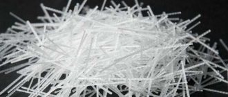
The main option for transferring flammable gases, oil and its products, warm and hot water for water supply and heating systems, and sewage, is their transportation over arbitrarily long distances through pipes. When operating pipelines, there is often a need to interrupt the supply of the working medium in case of accidents, to connect new branches to the main line, repair and maintain pipes, equipment and other purposes - this function is performed by shut-off valves.
Shut-off valves for a system with a medium transported through pipes, blocking the passage channel, have found wide application not only in the industrial and municipal spheres, but also in the construction industry, as well as in households. The average consumer encounters shut-off valves when installing individual heating communications, hot and cold water supply, connecting plumbing fixtures (toilets, sinks) and household appliances (washing machines, dishwashers).
Rice. 1 Shut-off valves for heating systems of individual houses - examples of placement
Working environment
The main regulatory document that explains what pipeline fittings (PVA) are and describes all related terminology and definitions is GOST 24856-2014.
The standard states that pipeline valves are technical devices placed on pipeline lines, equipment and containers.
The purpose of shut-off valves (VA) is to control the flow of the medium by changing the cross-section of the pipe passage.
Control refers to the ability of devices to shut off, open, regulate, distribute, mix and separate flows.
The working fluid controlled by the valves is liquids, gases and their mixtures, pulps, vapors, plasmas, bulk and powder substances, suspensions. In the industrial sector, valves are most often used to regulate the flow of hot and cold water, steam, oil and its products, oil, and natural combustible gas.
Rice. 2 Operating principle and design of typical valves and taps
Pressure classification
GOST 24856-2014 establishes the following groups of fittings depending on the pressure of the medium in the pipes they control:
Low pressure - capable of withstanding a pressure of the medium in the pipeline of no more than 2.5 MPa (25 bar).
Medium-pressure - operates when the working fluid is supplied under pressure from 2.5 to 10 MPa (25 - 100 bar).
High pressure - operated when the pressure of the medium moving in the communications exceeds 10 MPa (100 bar).
Instrumentation and automation devices in gas pipeline systems
In addition to all of the above, numerous instrumentation and automation devices (instruments and automation) are used in gas pipeline systems.
In addition to gas fittings, instrumentation and control systems are installed on gas pipelines. This allows for constant monitoring of the condition of the equipment and the progress of the technological process. And also quickly identify pre-emergency and emergency situations
The most popular devices used in gas systems are:
- gas alarms;
- equipment for emergency shutdown of incoming gas;
- equipment for measuring the volume of gas passed through;
- electronic regulators of the gas volume passed;
- autonomous power supplies;
- gas valves for automating various processes and optimizing the operation of pipelines;
- gas regulators for regulating the volume of medium passing through some section of the pipeline.
Such devices are high-tech equipment used in a wide variety of conditions.
Types of fittings on pipelines
The term “valve type” refers to its functions, the main ones being:
- constipation,
- regulation,
- prevention,
- obstacle to reverse movement,
- stream separation.
Shut-off valves (on-off, shut-off, stop) are technical devices that perform the function of hermetically shutting off the flow of the transported working fluid.
In addition to the main locking type, in the technical industry there are the following types of combined or multifunctional (combined, multifunction), combining different functions of fittings:
Shut-off and control (on-off and control) - in addition to completely blocking the flow, shut-off control valves for heating, water supply and other needs are capable of changing the volume of a moving medium by partially blocking the channel passage.
Stop and check - in addition to blocking the channel passage, it prevents the passage of the medium in the opposite direction.
Non-return shut-off (stop non-return) - in addition to preventing flow movement in the opposite direction, it implements the function of forced closing or limiting the movement of the shutter element.
Rice. 3 Sectional design of shut-off valves
Compensators.
During the operation of gas pipelines, the temperature change can reach several degrees, which causes stresses of several tens of MPa. Therefore, to prevent the destruction of the gas pipeline from temperature influences, it is necessary to ensure its free movement. Devices that ensure the free movement of pipes are compensators - lens, lyre-shaped and U-shaped. On underground gas pipelines, lens compensators are most widespread (figure below).
Types of shut-off valves and classification
The type of valve is its classification according to the direction of movement of the shut-off and control element relative to the flow of the medium and the determination of the distinctive design features.
GOST 24856-2014 regulates the following types of ZA:
- Gate is a device with a control element moving at right angles to the flow.
- A globe valve is a device with a shutter or adjusting element that moves parallel to the flow.
- Faucet, valve (ball, plug) - a device with a shutter-regulating element in the form of a rotating body or its fragment, turning around its axis. In this case, the shut-off unit can be located in an angular position relative to the direction of the medium flow.
- Butterfly valve is a type of shut-off valve in which the shutter or adjusting element is made in the shape of a disk. The disk rotates around an axis, which can be located perpendicular or angular to the flow.
Rice. 4 Shut-off valves on industrial pipelines
Valves
A valve is a device in which the movement of the locking element is carried out by means of a running nut and a spindle (threaded pair). The valve has the property of self-braking, so the shut-off element can be left in any intermediate position.
Main characteristics of valves:
- material of the main parts - gray cast iron of grade no lower than SCh18–36;
- nominal diameter, D (mm): 15, 20, 25, 32, 40, 50, 65, 80, 100, 125, 150, 200;
- type of connection to the pipeline: flange or coupling;
- valve seal material: fluoroplastic-4, acid-alkali-resistant rubber of medium hardness;
- working medium: steam, water;
- maximum temperature in the pipeline, K (°C) - 489 (225).
Purpose and scope of application
The fittings are divided into the following types according to their area of use:
- Industrial (industrial pipeline) - used in various industries without any special requirements from users.
- Special (tailored) - designed for operation in conditions with specific characteristics of the transported and environment.
- For hazardous facilities - used at facilities where reagents that are harmful and dangerous to human health (flammable, explosive, flammable, toxic and other substances) are used, as well as equipment operated under pressure from 0.07 MPa or at temperature parameters working fluid over 115 °C.
- Sanitary (sanitary, plumbing) - shut-off valves for water supply, mounted on sanitary equipment. The average consumer most often encounters ball valves installed under sinks and toilets in front of flexible hoses, when connecting washing machines and dishwashers to the water supply.
- Ship (ship, marine) - placed on pipe communications and equipment of ships.
- Vacuum - operating at pressures below atmospheric.
- Control (monitoring) - regulating the supply of medium to control, measuring equipment and devices.
- Cryogenic - operating in an environment with a temperature from 0 to 120 °K.
- Shut-off (quick-acting) - quick-acting in accordance with the production process.
- The inlet is of the reverse type, mounted at the end of the pipeline before the electric pump.
- Antisurge - responsible for reducing the difference in the flow rate of the working fluid of compressors.
Rice. 5 Plumbing fittings in public utilities
- Pressure-reducing (throttle) - performing the functions of reducing pressure in networks by increasing hydraulic resistance.
- Drain (bleed, blow-off, drain) - performs the functions of discharging large volumes of liquids from tanks and pipeline systems in a short time.
- Sampling and bleed - used when taking samples and determining the presence of a medium, discharging it from various types of tanks and boiler equipment.
- Wellhead, oil-and-gas field - designed for operation in the pipes of oil production wells, their piping and beyond the boundaries of pipelines.
- Oil and gas production or fountain (Christmas tree) - installed at the mouth of well pipes during oil and gas production.
- Fountain (wellhead) tree (christmas tree) is an auxiliary variety when installing wellhead devices, designed to ensure the normal functioning of the latter.
- With heating (with heating, jacketed) - has an electric cable built into the body or is covered with a heat-protective casing on top. A heat carrier, for example, steam or heated air, is supplied into the space between the housing and the casing.
- Energy (energy, power) - refers to special varieties for functioning at energy industry facilities.
Rice. 6 Flanges and weld ends
Expert advice
- It should be borne in mind that you cannot put plastic on the input - if it fails, it will take a long time to change it. Cast iron and steel rust – these materials should be discarded.
- Do-it-yourself installation of any gas pipeline elements is prohibited - and it is better not to experiment for safety reasons.
- Copper fittings are used for copper water supply systems. Soldering copper pipes and fittings is difficult - best left to a specialist.
- You should not use tow during installation - modern FUM tape insulates the joints more reliably and allows you to easily unscrew the threaded connection in the event of a breakdown.
- If it is necessary to weld a metal-plastic pipe, it is necessary to remove the top two layers of polypropylene and aluminum foil (there is a special device for this - a shaver). You cannot weld plastic at subzero temperatures.
- If you are replacing a product on a threaded connection and it does not unscrew, you should use a special thread lubricant (for example, WD-40).
- When installing the tap, the direction of liquid flow must coincide with the arrow on the tap.
Pipeline shut-off valves - connection methods
GOST 24856-2014 regulates the following types of fittings depending on the method of connection to pipelines:
- Flangless - the device does not have connecting flanges on the body, but it is mounted into a pipeline gap that has flanges at the pipe ends. To connect fittings, welding, fitting, nipple and other types of connections are used.
- Wafer or coupling (wafer) - has no flanges and is placed in the space between the line between its flange disks as connecting fittings for pipelines.
- Coupling (female, screwed) - has pipes on the body with threads applied to the inner shell.
- Butt-weld or welded (butt-weld) - has smooth connection bends on the body, usually cylindrical in shape, which are welded into a pipe break or to equipment or tanks.
- Flanged - usually equipped with flanged disks with holes for bolting, inserted into a pipeline break or connected to the flanges of equipment and tanks.
- Tsapkovaya ((male) screwed) - has cylindrical body bends for connection, equipped with an external thread and a collar.
- Union (union) - equipped with pipes with an external threaded notch.
Rice. 7 Pin connection with external thread and coupling connection with internal thread
Related article:
Flanged ball valve - design, application, installation, manufacturers . There is a separate article on our website dedicated to flanged ball valves. Features, device, characteristics, popular models. Take a look, it might be useful to read.
Cast iron valve with pressure lubrication
1 - channels; 2 - base of the plug; 3 - bolt; 4 - ball valve; 5 - gasket
In addition to lubricated valves, simple rotary valves are used, which are divided into tension, gland and self-sealing valves. These valves are installed on above-ground and on-site gas pipelines and auxiliary lines (pulse and purge gas pipelines, condensate collector heads, inlets).
In tension taps, mutual compression of the sealing surfaces of the plug and the body is achieved by screwing the tension nut onto the threaded end of the plug, equipped with a washer.
To create tension in the plug, the end of its conical part should not reach the washer by 2-3 mm, and the lower part of the inner surface of the body should have a cylindrical groove. This makes it possible, as the valve plug wears out, to lower it lower, tightening the shank nut, and thereby ensure tightness.
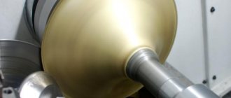
Hull shaping
The injection molding machine is produced in housings made using the following technologies:
- Cast - made using casting technology.
- and welded - consist of cast parts connected to each other by welding.
- and welded - made using the technology of casting body parts and stamping (rolling, forging) of internal cylindrical elements (shells) from metal sheets.
- Stamp-welded (die and welded, stamped and welded) - body parts are made using the technology of stamping (rolling, forging) of cylindrical elements (shells) and fastened to each other by welding.
- With a one-piece body (one-piece body) - during assembly, the body parts are fastened together by crimping, welded or glued.
- With a split body (split body) - the component parts of the body are connected to each other by means of a threaded notch.
Rice. 10 Types of oil seals
Lens compensator
1 - pipe; 2 - flange; 3 - shirt; 4 - half lens; 5 - rib; 6 - paw; 7 - nut; 8 - thrust
Lens compensators are made by welding from stamped half-lenses. To reduce hydraulic resistance and prevent clogging inside the compensator, install
a guide pipe welded to the inner surface of the compensator on the gas inlet side. The lower part of the lenses through the holes in the guide pipe is filled with bitumen to prevent the accumulation and freezing of water in them.
When installing the compensator in winter, it is necessary to stretch it a little, and in summer, compress it with tie rods. After installation, the rods must be removed. Compensators, when installed next to valves or other devices, provide the ability to freely dismantle flange fittings and replace gaskets (figure below).
Types of seals
GOST 24856-2014 adopted the following classification of pipeline fittings by type of sealing elements:
Glandless , packless - a rod or spindle seal, implemented without the use of oil seals.
Membrane or diaphragm (diaphragm, membrane) - a device with a shutter in the form of a membrane, which simultaneously performs the sealing or sealing functions of parts of the body, shutter, and elements moving outside.
Gland packing, packed - having seals for the rod, spindle or other external moving parts in the form of oil seals.
Bellows - for spindle or rod sealing, a bellows seal is used externally; sometimes it functions as a force transmitter or is a sensitive element.
Rice. 11 Bellows seal
Types of shut-off valves based on valve design
Pipeline fittings of different types differ in the design of their actuating units (gates), which ensure the closure of the pipeline passage channel. Also, the design of the locking mechanism in many cases determines the overall dimensions and area of use of the injection molding machine.
Valves
A valve is a type of injection molding machine whose shut-off or adjusting element moves at an angle of 90 degrees relative to the transported flow.
Blocking flow movement using valves is one of the most commonly used methods in the industrial and utility industries; they are usually used on pipelines with a diameter of 50 mm and above. GOST 24856-2014 regulates the following types of valves:
- Wedge gates are devices with a moving gate shaped like a wedge. When lowered, it rests on the surfaces of the seat rings, placed between each other at a similar angle. For example, a cast iron valve with a rubber-coated wedge 30h39r.
- Parallel gates - have saddle seals placed mutually parallel.
- With a retractable spindle, rod (gate valve with rising stem) - when opening or closing the passage channel, the rotating spindle or rod on which the lock is attached moves relative to the central axis of the connecting taps by the length of the working stroke.
- With a non-rising spindle (gate valve with non-rising stem) - when opening and closing the passage channel, the rotating spindle does not move in a forward direction relative to the central axis of the device, and its threaded section does not extend beyond the internal body area.
Rice. 12 Wedge-shaped valve - a structural device using the example of model 30s41nzh
- Gate or knife (slide gate, slab gate) - the gate element is a plate with a parallel arrangement of seat rings. (You can learn about gate valves in a separate article).
- wedge gate - the locking element is made of two inclined discs. In their placement, the ability to self-align relative to the body seat rings is structurally implemented.
- With an elastic wedge (flexible wedge gate) - has a wedge shape and consists of two inclined disks. Between the disks there are elastic or rigid moving parts, the movement or deformation of which allows the wedge to self-align relative to the body seat rings.
- parallel disc gate - has two parallel disks located relative to each other. When lowering the movable valve element, one of the parts of the assembly rests against the bottom of the passage channel, the disks diverge and are tightly pressed against the seat sealing rings.
- Rotatable gate - block the movement of the flow of the working medium by rotating the gate element placed in the passage channel around its axis.
- Hose gate (pinch gate) is a special type of valve that works to shut off a section of a pipeline whose passage channel in the gate is made of a plastic flexible hose. When operating in closing mode, the shutter element presses on the hose, thereby stopping the movement of the working fluid along it.
Rice. 13 Slider (knife) valve - structural device
Valves
Shut-off valves are a type of valve in which the passage channel is blocked by a specially made part in the form of a piston, called a spool. In the design of valve fittings, the channel passage in the body is designed in such a way that the valve can close it from above. The passage channel has a curved shape with a shutter perpendicular to the inlet and outlet pipes.
The spool is usually made in the form of a plate, cylindrical piston, sphere or needle. Its sealing surface in contact with the seat ring can be flat, conical or spherical.
GOST 24856-2014 regulates the following types of valves:
- Shut-off (on-off, stop) - designed to lock the passage channel, they have a valve-shaped design.
- Regulating (control) - control the supply volume of the transported working flow by moving the valve a certain distance.
- Safety valve - the valve performs protective functions in the pipeline or on equipment.
- Shut-off (isolation) - characterized by a fast response time, blocking the flow of the transported working fluid in the event of emergency or emergency situations.
Rice. 14 Hose seal
- Hermetic, hermetic valve (tight disc-type) - used in ventilation systems, structurally similar in design to a disc valve, moving in the final stage perpendicularly or parallel to the central axis of the pipeline.
- Normally closed (NC) (air-to-open, normally closed) - a valve directly controlled by an electric actuator or auxiliary mechanism that creates forces to move the shut-off or adjusting element. In the absence of electricity, they are set to the “closed” position.
- Normally open (NO) (air-to-close, normally open) - a device with a direct electric drive or an auxiliary mechanism that moves the spool to lock or adjust the size of the passage channel. In the absence of power supply, it spontaneously sets to the “open” position.
- An electromagnetic valve (solenoid) is a device with a drive in the form of an electromagnetic coil and its armature connected to a spool. The drive can be located either inside the housing or placed outside its surface.
Construction of gas wells
a - installation of a valve in a well: 1 - case; 2 - valve; 3 - carpet; 4 — hatch; 5 — lens compensator; 6 - gas pipeline; b - construction of a small-sized well: 1 - outlet; 2 - tap; 3 - gasket; 4 - well wall
The wells have hatches that can be easily opened for inspection and repair work. On the roadway, hatches are installed at the level of the road surface, and on unpaved driveways - 5 cm above ground level with a blind area of 1 m in diameter around the hatches. Where possible, it is recommended to move the valve control under the carpet.
Where gas pipelines cross the walls of the well, cases are installed, which are sealed with bitumen for density. Wells must be waterproof. An effective remedy against the penetration of groundwater is waterproofing the walls of wells. In case of water penetration, special pits are installed in the wells to collect and remove it.
On gas pipelines with a diameter of up to 100 mm, when transporting dried gas, small-sized wells are installed (figure above) with fittings installed in the upper part, which ensures servicing of the fittings from the surface of the ground. In such wells, taps are installed instead of valves.
In forced lubrication valves (figure below), sealing is achieved by introducing a special grease under pressure between the sealing surfaces. The lubricant tucked into the hollow channel of the upper part of the plug is pumped through the channels into the gap between the body and the plug by screwing the bolt. The plug rises slightly upward, increasing the gap and ensuring ease of rotation; the ball valve and brass gasket prevent the grease from being squeezed out and gas from penetrating out.
Drives
A valve drive is a device that ensures movement of the locking element, as well as creating the necessary force to ensure sealing of the valve. Drives are used in situations where shut-off valves have large overall dimensions and manual rotation of the flywheels requires the application of too much physical effort, incomparable to human capabilities. Another important function of the drives is the possibility of remote control, which allows you to quickly carry out all work on shutting off or regulating the flow of media in pipeline networks without human presence.
GOST 24856-2014 establishes the following classification of shut-off valves by type of actuator:
- Manual - human physical strength is used to move the actuator.
Rice. 18 Types of drives
- Electric (electric) - to perform its functions, the fittings use electromechanical mechanisms that provide translational or rotational (multiple or partial) movement of the spindle.
- Electromagnetic (solenoid) - the energy conversion of electric current occurs in an electromagnetic coil, which, due to its field, moves a ferromagnetic core connected to the spindle of the device. Based on the method of arrangement of the electromagnetic coil, a distinction is made between those built into the fittings and block units located outside the device body. Based on the type of action of the electromagnet, there are designs of reversible, pulling, pushing, and rotary types.
- Pneumatic - compressed air is used to control the shut-off or control mechanism.
- Hydraulic drive (hydraulic) - the movement of the actuator is carried out using fluid supplied under pressure.
- Pneumatic and hydraulic is a combined design, the actuating element of which moves with the help of compressed air and liquid supplied under pressure.
- Electrohydraulic (electrohydraulic) - the movement of the actuator is realized by supplying the mechanism with electric current and liquid under pressure.
Rice. 19 Materials for manufacturing a household ball valve using the example of the Bugatti model
Product advantages
The shut-off valve has the following advantages:
- A design that is completely suitable for repair in the event of any part failure.
- High operational reliability and tightness of the ceiling.
- The opening speed of the passage is sufficiently low, which eliminates the possibility of harmful hydraulic shocks in the system.
- Some models can be used to throttle the flow.
- It does not require great physical force to be operated by operating personnel. This eliminates the need for long levers in manually operated valves and an expensive electric drive in automatic models.
Shut-off valves for heating and water supply - manufacturing materials
Shut-off valves for heating and water supply systems are made from a wide range of metal and polymer materials.
The housings of units for industrial and municipal use are mainly made of cast iron and various grades of steel - both low-carbon and alloyed with various additives, which give the metal increased anti-corrosion properties and heat resistance.
The vast majority of shut-off valves for water supply used in households are made of brass without or with chrome plating, and less often of stainless steel. Recently, due to the popularity of polymers, shut-off valves for water supply systems are often produced in housings made of PP polypropylene or HDPE low-density polyethylene.
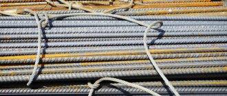
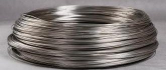
Gate wedges for large-sized valves are produced from low-carbon steels, with overlays made of corrosion-resistant, hard-alloy, heat-resistant and wear-resistant materials. Sealing rings in seats are also made by fusing metals with high physical and chemical characteristics (bronze, stainless steel).
The spheres of ball valves used in everyday life are made of brass or bronze with a chrome coating, as well as stainless steel.
Handwheels, consoles and handles are made of steel, cast iron; in small-sized appliances for household use, they are made of plastic, aluminum, and steel.
In addition to gland seals, shut-off control valves for heating systems for industrial, municipal and domestic use are equipped with sealing materials made of rubber, graphite, Teflon (PTFE), ethylene propylene diene (EPDM) and acrylonitrile butadiene (NBR), synthetic and fluorinated (SFC, Viton) rubbers.
Rice. 20 Brass small-sized shut-off valves in section
Shut-off valves - main technical parameters
The technical characteristics of shut-off valves are important when used in industrial, municipal and household sectors. The main parameters are often indicated on the body of products when they are cast or stamped; usually the symbols have a protruding raised surface. GOST 24856-2014 gives the following definitions for the main characteristics of shut-off valves:
- Nominal parameters are numerical indicators of functional characteristics from a standardized range of values, given without tolerances for deviations.
- Nominal or conditional pressure PN (nominal pressure) - the maximum pressure indicator, expressed in kilograms per second, bars or atmospheres at a constant temperature of the transported medium of 20 ° C, at which the shut-off valves of pipelines operate during the service life prescribed by state standards.
- Nominal diameter DN (nominal diameter) is a dimensional parameter approximately equal to the internal cross-sectional size of devices. The DN indicator is measured in millimeters and is taken equal to one of the values of the standardized series. DN serves as the main dimensional indicator when choosing any type of fittings.
Rice. 21 Polymer taps
- Operating pressure (line pressure; operating pressure; service pressure; working pressure) - the highest excess pressure at which pipeline fittings fulfill their service life with selected materials and a given temperature.
- time is the time interval during which the locking element moves from the “open” to the “closed” position or vice versa.
- Flow area or passage (flow area) - a section at an angle of 90 degrees relative to the direction of flow at any point in the passage section of the fittings.
- Leak or leakage (leak; leakage) - penetration of the transported medium outside the dimensions of the housing, caused by the difference in pressure between the supplied flow and atmospheric air. It is measured in the volume of the working fluid coming out per unit time when the shutter mechanism is closed.
- Normal or standard conditions (normal conditions) - characteristics of the environment for measuring the volume of gases: correspond to a temperature of 20 ° C and an atmospheric pressure of 760 mm Hg. Art. at zero humidity.
- Design temperature - temperature parameters of the casing walls of the device, equal to the arithmetic average of the values measured on the inner and outer shell of the device when operating under normal operating conditions.
Rice. 22 How to correctly formulate the name of the valve, its symbol and an example of body marking
Shut-off valves for pipelines are widely used in all industries, utilities, and households to control the flow of media transported through pipelines. The shut-off valves chosen by the average consumer for heating and water supply must meet the requirements of compatibility with the physical and chemical characteristics of the supplied working medium, have the appropriate design, materials of manufacture, and basic technical parameters.
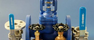
Valves
Products of this type are used on production lines and in transport pipelines for industrial purposes. The valve is manufactured in the following versions:
- with manual control;
- with electric drive in standard and explosive versions;
- with hydraulic drive.
On large-diameter shut-off valves with manual control, a gearbox with a worm, bevel or cylindrical gear is installed to reduce the force on the flywheel. If the valve spindle is located horizontally, the electric drive is mounted on a support, the worm and roller bearing are thickly lubricated with oil.
Main characteristics:
- conditional pressure, P, MPa (kgf/sq. cm): 0.16 (1.6) – 25.0 (250);
- nominal diameter, D, mm: 50–2000;
- working environment temperature, K (°C): +213 (-60) − +838 (+565).