This homemade welding machine from LATR 2 is built on the basis of a nine-amp LATR 2 (laboratory adjustable autotransformer) and its design provides for adjustment of the welding current. The presence of a diode bridge in the design of the welding machine allows welding with direct current.
Infrared heater with thermostat + lamp
Quick heating of the room, individual temperature in each room…
More details
Do-it-yourself Latra welding machine - Metalworker's Guide
If you need to perform some simple welding work for domestic needs, it is not at all necessary to purchase an expensive factory unit. After all, if you know some subtleties, you can easily assemble a welding machine with your own hands, which will be discussed below.
Any welding machines can be electric or gas. It’s worth saying right away that homemade welding machines should not be gas. Since they include explosive gas cylinders, you should not keep such a unit at home.
Therefore, in the context of self-assembly of structures, we will talk exclusively about electrical options . Such units are also divided into varieties:
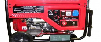
- Generator units are equipped with their own current generator. A distinctive feature is its large weight and dimensions. This option is not suitable for home needs, and it will be difficult to assemble it yourself.
- Transformers - such installations, especially the semi-automatic type, are very common among those who make welding equipment themselves. They are powered from a 220 or 380 V network.
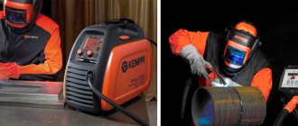
- Inverters - such installations are easy to use and ideal for home use; the design is compact and lightweight, but the electronic circuit is quite complex.
- Rectifiers - these devices are easy to assemble and use for their intended purpose. With their help, even a beginner can make high-quality welds.
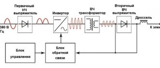
How to make an inverter-type welding machine
To assemble an inverter at home, you will need a circuit that will allow you to comply with the necessary parameters. It is recommended to take parts from old Soviet devices:
- transistors;
- diodes;
- chokes;
- finished transformers;
- capacitors;
- resistors;
- thyristors.
The following parameters can be selected for the device:
- It must work with electrodes whose diameter does not exceed 5 mm.
- The maximum operating current is 250 A.
- Voltage source - household network at 220 V.
- The welding current adjustment varies from 30 to 220 A.
The tool includes the following components:
- power unit;
- rectifier;
- inverter
We start by winding the transformer and proceed in the following sequence:
- Take a ferrite core.
- Perform the first winding (100 turns using 0.3 mm PEV wire).
- The second winding is 15 turns, wire with a cross-section of 1 mm).
- The third winding is 15 turns of 0.2 mm PEV wire.
- The fourth and fifth - respectively 20 turns of wires with a cross section of 0.35 mm.
- To cool the transformer, use a computer fan.
In order for transistor switches to operate continuously, voltage should be applied to them after the rectifier and capacitors. Assemble the rectifier block according to the diagram on the board, and secure all components of the device in the housing. You can use an old casing from a radio device , or you can make it yourself.
An LED indicator is installed on the front of the case , which shows that the device is connected to the network. Here you can install an additional switch, as well as a protective fuse. It can also be installed on the back wall and even in the case itself.
It all depends on its size and design features. A variable resistance is installed on the front of the housing; it can be used to regulate the operating current . When you have assembled all the electrical circuits, check the device with a special device or tester and you can test it.
DIY welding transformer
The assembly of the transformer version will be slightly different from the previous one. This unit operates on alternating current, but for welding with direct current you need to assemble a simple attachment for it.
To work, you will need transformer iron for the core, as well as several tens of meters of thick wire or thick copper busbar. All this can be found at the metal collection point. The core is best made U-shaped, toroidal or round. Many also take the stator from an old electric motor.
The assembly instructions for the U-shaped core look like this:
- Take transformer iron with a cross-section from 30 to 55 m2. If the figure is higher, the device will be too heavy. And if the cross section is less than 30, the device will not be able to work correctly.
- Take a copper winding wire with a cross-section of about 5 mm2, equipped with heat-resistant fiberglass or cotton insulation. Insulation is important because during operation the winding can heat up to 100 degrees or more. The winding wire has a square or rectangular cross-section. However, such an option is difficult to find. An ordinary one with a similar cross-section will do, but you will only need to remove the insulation from it, wrap it in fiberglass and thoroughly soak it with electrical varnish, and then dry it. The primary winding has 200 turns.
- The secondary winding will require about 50 turns. There is no need to cut the wire. Connect the primary winding to the network, and on the secondary wires find a place where the voltage is about 60 V. To find such a point, unwind or wind additional turns. The wire can be aluminum, but the cross-section must be 1.7 times larger than for the primary winding.
- Install the finished transformer into the housing.
- To bring out the secondary winding, copper terminals are required. Take a tube with a diameter of 10 mm and a length of about 4 cm. Rivet its end and drill a hole with a diameter of 10 mm, and insert the end of the wire, previously cleared of insulation, into the other end. Next, crimp it with light hammer blows. To strengthen the contact of the wire with the terminal tube, apply notches to it with a core. Screw homemade terminals to the body with nuts and bolts. It is best to use copper parts. When winding the secondary winding, it is advisable to make taps every 5-10 turns, they will allow you to change the voltage on the electrode in steps;
- To make an electrical holder, take a pipe with a diameter of about 20 mm and a length of about 20 cm. At the ends, about 4 cm from the end part, cut out recesses to half the diameter. Insert the electrode into the recess and press it with a spring based on a welded bush of steel wire with a diameter of 5 mm. Attach the same wire that was used for the secondary winding to the second terminal using a nut and screw. Place a rubber tube with a suitable inner diameter onto the holder.
It is best to connect the finished device to the network using wires with a cross-section of 1.5 cm2 or more, as well as a switch. The current in the primary winding usually does not exceed 25 A, and in the secondary winding it ranges from 6-120 A.
When working with electrodes with a diameter of 3 mm, stop every 10-15 to allow the transformer to cool down . If the electrodes are thinner, this is not necessary. More frequent breaks are needed if you are working in cutting mode.
Features of spot welding
Do-it-yourself spot welding has a number of advantages over other types:
- efficiency;
- ease of implementation;
- strength of the resulting connections.
The quality of the welded joint depends on several components, primarily on the material from which the electrodes are made. It is recommended to use copper rods for these purposes - they are durable and have high electrical and thermal conductivity. An important parameter is the cross-section of the electrode. It should be two to three times smaller in diameter than the weld point.
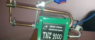
You can make a spot welding machine (spotter) yourself - the spot welding scheme is quite simple. To perform resistance welding, you will need a transformer with a power of more than 1 kW. Often, an element from a failed microwave oven is used for these purposes. The size of the transformer should allow 2–3 turns of the winding to be made with a thick cable, and the cable length should be 1.5 m.
The secondary winding of the transformer is replaced, leaving the primary winding intact. The new secondary winding is made of insulated aluminum wire with a diameter of 1–2 mm, to which lugs are attached. A powerful wire will provide a current of 1000 A.
Making the device yourself
After the transformer is ready, the primary winding is connected to a power source and the voltage on the secondary winding is determined (2–2.8 V is obtained).
A transformer, a cable with a switch are sequentially mounted to the housing, the parts of which can be made of wood or chipboard, and grounding is done.
After completing the installation of the housing, welding pliers are installed. It is better to make the electrodes from copper wire and secure them in duralumin holders on wooden blocks. The polished “tip” of an old, unnecessary soldering iron is suitable for the role of electrodes.
The cable is connected to the electrodes using four terminals. The top two are bent towards each other - electrodes are inserted into them, and the ends of the secondary winding cable are connected to the bottom two.
The lower electrode is often fixed in a stationary state, while the upper one moves. Homemade contact welding is connected to the network via a 20 A circuit breaker.
The choke for welding is used to regulate the current strength - without it it will be maximum. Connect the inductor to the secondary winding, it adds resistance and reduces the current.
The resistance welding machine can be equipped with a fan that acts as a cooling system.
Homemade spot welding operates on a 220 V network.
Advice. To increase the power of the spotter, several transformers are used, but this entails a voltage drop in the network. Therefore, do-it-yourself resistance welding is carried out using homemade devices, the power of which is limited - it provides a current of 1000–2000 A.
The quality of do-it-yourself welding work depends on several conditions:
- pressure on the metal - the clamping force must be sufficient;
- electrode diameter;
- current flowing through the electrode;
- The pressing time should be longer than the welding time (the electrodes should be pressed a little longer than the current flows).
Radio circuits. — Welding machine from LATRA
materials in category
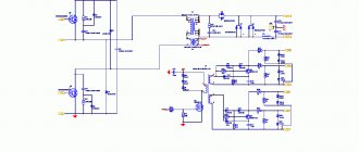
This device is based on an easily upgradeable 9-amp laboratory autotransformer LATR 2 and a homemade thyristor mini-regulator with a rectifier bridge. They allow you not only to safely connect to a household AC lighting network with a voltage of 220V, but also to change Usv on the electrode, and therefore select the desired value of welding current.
Operating modes are set using a potentiometer.
Together with capacitors C2 and C3, it forms phase-shifting chains, each of which, when triggered during its half-cycle, opens the corresponding thyristor for a certain period of time.
As a result, an adjustable 20-215 V appears on the primary winding of the welding T1. Transforming in the secondary winding, the required -Usv make it easy to ignite the arc for welding on alternating (terminals X2, X3) or rectified (X4, X5) current.
Scheme converting LATR into a welding machine
A welding transformer based on the widely used LATR2 (a), its connection to the circuit diagram of a homemade adjustable welding machine for alternating or direct current (b) and a voltage diagram explaining the operation of a transistor regulator of the electric arc combustion mode.
Resistors R2 and R3 bypass the control circuits of thyristors VS1 and VS2. Capacitors C1, C2 reduce the level of radio interference accompanying an arc discharge to an acceptable level. A neon light bulb with a current-limiting resistor R1 is used as a light indicator HL1, signaling that the device is connected to the household power supply.
To connect the “welder” to the apartment electrical wiring, a regular X1 plug is used. But it is better to use a more powerful electrical connector, which is commonly called a “Euro plug-Euro socket”. And as a switch SB1, a “packet” VP25, designed for a current of 25 A and allowing you to open both wires at once, is suitable.
As practice shows, it makes no sense to install any kind of fuses (anti-overload circuit breakers) on the welding machine. Here you have to deal with such currents, if exceeded, the protection at the network input to the apartment will definitely work.
To manufacture the secondary winding, the casing-guard, current-collecting slider and mounting hardware are removed from the base LATR2.
Then, reliable insulation (for example, made of varnished fabric) is applied to the existing 250 V winding (the 127 and 220 V taps remain unclaimed), on top of which a secondary (step-down) winding is placed.
And this is 70 turns of an insulated copper or aluminum busbar with a diameter of 25 mm2. It is acceptable to make the secondary winding from several parallel wires with the same general cross-section.
It is more convenient to carry out winding together. While one, trying not to damage the insulation of adjacent turns, carefully pulls and lays the wire, the other holds the free end of the future winding, protecting it from twisting.
The upgraded LATR2 is placed in a protective metal casing with ventilation holes, on which there is a mounting plate made of 10-mm getinax or fiberglass with a packet switch SB1, a thyristor voltage regulator (with resistor R6), a light indicator HL1 for connecting the device to the network and output terminals for welding on AC (X2, X3) or direct (X4, X5) current.
In the absence of a basic LATR2, it can be replaced with a homemade “welder” with a magnetic core made of transformer steel (core cross-section 45-50 cm2). Its primary winding should contain 250 turns of PEV2 wire with a diameter of 1.5 mm. The secondary one is no different from the one used in the modernized LATR2.
At the output of the low-voltage winding, a rectifier block with power diodes VD3-VD10 is installed for DC welding. In addition to the indicated valves, more powerful analogs are also quite acceptable, for example, D122-32-1 (rectified current - up to 32 A).
Power diodes and thyristors are installed on heat sinks, the area of each of which is at least 25 cm2. The axis of the adjusting resistor R6 is brought out from the casing. A scale with divisions corresponding to specific values of direct and alternating voltage is placed under the handle. And next to it is a table of the dependence of the welding current on the voltage on the secondary winding of the transformer and on the diameter of the welding electrode (0.8-1.5 mm).
Of course, homemade electrodes made from carbon steel “wire rod” with a diameter of 0.5-1.2 mm are also acceptable. Blanks 250-350 mm long are covered with liquid glass - a mixture of silicate glue and crushed chalk, leaving the 40 mm ends unprotected, which are necessary for connecting to the welding machine. The coating must be thoroughly dried, otherwise it will start to “shoot” during welding.
Although both alternating (terminals X2, X3) and direct (X4, X5) current can be used for welding, the second option, according to reviews from welders, is preferable to the first. Moreover, polarity plays a very important role. In particular, when applying a “plus” to the “mass” (the object being welded) and, accordingly,
When connecting an electrode to a terminal with a minus sign, the so-called direct polarity occurs. It is characterized by the release of more heat than with reverse polarity, when the electrode is connected to the positive terminal of the rectifier, and the ground is connected to the negative terminal.
Reverse polarity is used when it is necessary to reduce heat generation, for example, when welding thin sheets of metal.
Almost all the energy released by the electric arc goes to the formation of a weld, and therefore the depth of penetration is 40-50 percent greater than with a current of the same magnitude, but of straight polarity.
https://www.youtube.com/watch?v=_ODVpELuBrw
And a few more very significant features. An increase in the arc current at a constant welding speed leads to an increase in the depth of penetration. Moreover, if the work is carried out on alternating current, then the last of these parameters becomes 15-20 percent less than when using direct current of reverse polarity. The welding voltage has little effect on the penetration depth. But the width of the seam depends on Ust: it increases with increasing voltage.
Some types and features of contact welding
Depending on the size and shape of the heated area, resistance welding is of three types.
- Spot welding - the material is “stitched” with single high-temperature “injections”, the seam is not airtight.
- Suture - the molten edges of the parts are connected to each other to obtain a sealed seam. An example of this type of joining of parts is soldering a metal liquid tank. Essentially, a seam joint consists of many overlapping points.
- Butt joint - the joint area is wide, one part is “put on” another, at the joints a complete merging of the parts into a homogeneous element is formed. This type of connection is most often used to weld pipes.
Operation of the device on the car body
Do-it-yourself spot welding does not require complex devices, you do not need a special table for welding, but compliance with safety precautions when carrying out welding procedures is mandatory.
How to make an electronic LATR?
The main reason for creating an electronic LATR with your own hands is the abundance of unreliable regulators on the electrical goods market. A way out of the situation may be an industrial-type sample, but such specimens are expensive and have impressive dimensions, which makes it difficult to use at home.
Electronic LATR device diagram.
What is the device
It is worth mentioning that laboratory autotransformers (LATR) were widely used half a century ago. Previous versions of the device had a current-collecting contact, which was located on the secondary winding. This made it possible to smoothly change the output voltage (its value).
If all kinds of laboratory instruments were connected, there was an option to quickly change the voltage. For example, if necessary, it was easy to influence the degree of heating of the soldering iron, adjust the brightness of the lighting, the speed of the electric motor, and much more. This is a kind of regulating power supply.
Figure 1. Scheme of a simple version of LATR.
The current version of LATR has various modifications. In general, it can be considered a transformer in which an alternating voltage of one value is transformed into an alternating voltage of another. The device is widely used as a voltage stabilizer. The main feature is the ability to change the voltage at the output of the device. LATRs come in several versions:
- single-phase;
- three-phase.
The three-phase version consists of three single-phase laboratory autotransformers mounted in a single housing. By the way, there are significantly fewer people who want to become the owner of a three-phase option.
A simple device for regulation
There is a very simple version of LATR, which is available even for beginners; its diagram is shown in Fig. 1. The voltage range regulated by such a device is within 0-220 volts. This homemade regulator has a power of 25-500 W. The power of the device can be increased by installing thyristors VD1 and VD2 on radiators.
Semiconductor devices (we are talking about thyristors VD1 and VD2) should be connected in parallel with the load R1. The current they pass has opposite directions.
When the device is connected to the network, the thyristors remain closed, unlike capacitors C1 and C2, which are charged by resistor R5.
If there is a need, using resistor R5 you can change the voltage that is obtained during load. The resistor and capacitors create a phase-shifting circuit.
Figure 2. LATR with a bipolar transistor.
A phase-shifting circuit is an electrical four-port network, the harmonic signal at the output of which is shifted in phase relative to the input signal. They are common in self-propelled guns as adjustment devices that provide stability and the necessary quality of control. Special cases are differentiating and integrating chains.
This technical solution allows you to use not half the power for the load, but full power. This is achieved due to the fact that both half-cycles of alternating current are used.
The disadvantages include the form of alternating voltage at the load. In this version it is not strictly sinusoidal. The specific operation of semiconductor devices is the main reason. The presence of such a feature can cause interference in the network. But they can be eliminated by additionally installing chokes (series load filters) on the circuit. Such filters can be found even in a faulty TV.
Voltage regulator: version with transformer
A laboratory autotransformer, which will not cause interference in the network and is capable of producing a sinusoidal voltage at the output, is a little more complicated than the previous one.
Its circuit (Fig. 2) contains a bipolar transistor VT1. It acts as a regulatory element in such a device. The power of this transistor is determined depending on the required load. In the circuit, it is connected in series with the load and functions as a rheostat. This option provides the ability to adjust the operating voltage during both active and reactive loads.
Unfortunately, there is a drawback here too. It lies in the fact that the activated control transistor generates too much heat. To eliminate it, you will need a heat sink that will have sufficient power. In this case, the area of such a radiator must be at least 250 cm².
Electrodes for spot welding
Do-it-yourself spot welding done at home is suitable for a small amount of work. It is recommended to let the device cool down after working with 10-14 electrodes.
The difference between multi-point equipment and its analogues is the work with metal workpieces of a certain shape and size.
Multipoint devices are rare, but are universal for contact pairing of elements. Only experts can re-adjust it.
Contact welding of parts is impossible in the absence of electrodes made of alloys with a high level of thermal conductivity.
Electrodes favor the compression of metals and conduct current to the surface of the elements. The level of heat concentration depends on the tips - thin mechanisms wear out quickly and need constant sharpening.
There are several forms of manufactured tips.
It is possible to extend the life of the tips by following the tips below:
- Electrodes are selected according to the criteria of the metal used in the work;
- Ensure their safety as much as possible;
- For heavy welding, use more massive tips;
- Use a water jacket.
Experts advise not to file the tips due to the appearance of unevenness, which will generally negatively affect the quality of work.
What is an autotransformer, how to assemble a LATRA with your own hands and a diagram
Many people are driven to make a laboratory autotransformer (LATR) with their own hands by the excess of low-quality regulators on the electrical market. You can also use an industrial type, however, such samples are too large and expensive. It is because of this that it is difficult to use them at home.
What is an electronic LATR?
Autotransformers are needed to smoothly change current voltage with a frequency of 50-60 Hz during various electrical work. They are also often used when it is necessary to reduce or increase alternating voltage for household or building electrical equipment.
Transformers are electrical equipment that is equipped with several windings connected inductively. It is used to convert electrical energy by voltage or current level.
By the way, electronic LATR began to be widely used 50 years ago. Previously, the device was equipped with a current-collecting contact. It was located on the secondary winding. This made it possible to smoothly adjust the output voltage.
When various laboratory devices , there was an option to quickly change the voltage. For example, if desired, you could change the degree of heating of the soldering iron, adjust the speed of the electric motor, the brightness of the lighting, etc.
Currently, LATR has various modifications. In general, it is a transformer that converts alternating voltage of one value to another. Such a device serves as a voltage stabilizer. Its main difference is the ability to adjust the voltage at the output of the equipment.
There are different types of autotransformers:
The last type is three single-phase LATRs installed in a single structure. However, few people want to become its owner. Both three-phase and single-phase autotransformers are equipped with a voltmeter and an adjustment scale .
Scope of application of LATR
Autotransformer is used in various fields of activity, among them:
- Metallurgical production;
- Utilities;
- Chemical and petroleum industries;
- Production of equipment.
In addition, it is needed for the following work: manufacturing household appliances, researching electrical equipment in laboratories, setting up and testing equipment, creating television receivers.
In addition, LATR is often used in educational institutions to conduct experiments in chemistry and physics lessons. It can even be found in some voltage stabilizer devices. Also used as additional equipment for recorders and machine tools. In almost all laboratory studies, it is LATR that is used as a transformer, since it has a simple design and is easy to operate.
An autotransformer, unlike a stabilizer, which is used only in unstable networks and produces a voltage of 220V at the output with a varying error of 2-5%, produces the exact specified voltage.
According to climatic parameters, the use of these devices is allowed at an altitude of 2000 meters, but the load current must be reduced by 2.5% for every 500 m rise.
The main disadvantages and advantages of an autotransformer
The main advantage of LATR is higher efficiency , because only some of the power is transformed. This is especially important if the input and output voltages are slightly different.
Their disadvantage is that there is no electrical insulation between the windings. Although in industrial electrical networks the neutral wire is grounded, so this factor will not play a special role, moreover, less copper and steel are used for the windings for the cores, as a result, less weight and dimensions. As a result, you can save a lot.
The first option is a voltage changer
If you are a novice electrician, then it is better to first try to make a simple LATR model, which will be regulated by a voltage device - from 0-220 volts. According to this scheme, the autotransformer has a power of 25-500 W.
To increase the regulator power to 1.5 kW, you need to place thyristors VD 1 and 2 on radiators. They are connected in parallel to the load R 1. These thyristors pass current in opposite directions.
When the device is connected to the network, they are closed, and capacitors C 1 and 2 begin to charge from resistor R 5. If necessary, they also change the voltage value during load.
In addition, this variable resistor, together with the capacitors, forms a phase-shifting circuit.
This technical solution makes it possible to use two half-cycles of alternating current at once. As a result, full power is applied to the load rather than half.
The only drawback of the circuit is that the shape of the alternating voltage during load, due to the specific operation of the thyristors, is not sinusoidal. All this leads to interference on the network. To correct the problem in the circuit, it is enough to build filters in series with the load. They can be pulled out of a broken TV.
Welding types
Welding is a process in which parts are joined by melting using local heating. This is the most durable type of fusion of materials, since the connection occurs at the interatomic level. Almost any material can be welded, but in the automotive industry this procedure is used to obtain a strong mechanical connection of metals or alloys. To melt metal, a high temperature is required: for steel above 1300 ° C, for copper - 1000 ° C, for aluminum - 660 ° C. Energy sources to achieve such temperatures can be different:
- electric arc;
- gas flame;
- ultrasound;
- electron beam;
- laser.
Spot welding uses an electric arc to melt and join materials. Depending on the type of energy used, three types of welding are distinguished:
- mechanical, which uses the thermal energy of friction and pressure on parts;
- thermal, when materials melt from a high temperature achieved by burning gas or high current;
- thermomechanical: a combination of high temperatures and pressure on parts leads to melting and fusion of the material.
Welding nails with a machine
The type of connection is also determined by the type of alloy.
Spot Welding Procedure
Before welding, the parts are cleaned, removing dust, corrosion elements, paint or oil residues - these interferences impair the quality of the connection. The thickness of the steel in the welded parts is no more than 3 mm.
The prepared metal parts are clamped with electrodes.
Current is applied to the electrodes; point contact has an effect on the metal - it heats it to the melting point at the point of contact with the electrodes.
Performing welding work does not require adjusting the current value during the process; visual control is sufficient. They focus on the heating time, which is 0.5–3 seconds (no more than five): the speed of current passing through a part 1 mm thick during operation of the device is 0.1–1 second, and the thickness of the parts being welded does not exceed 3 mm. If desired, the spot welding machine can be equipped with a time relay.
An example of the work of a professional welder
The current power sufficient for welding parts 1 mm thick is 3–5 kW. The current strength (on copper electrodes) should be from 50 A on 1 surface. At lower values, proper heating does not occur, the metal does not melt, and fusion becomes impossible.
Then the current is turned off, and the compression of the parts by the electrodes is increased.
At the point where the current is applied and the parts come together under the pressure of the electrodes, contact and bonds of atoms are formed - the welded joint is ready.
Over time, the electrodes melt, so the contact cone must be periodically ground to keep the tip sharp.
After turning off the device, it is recommended to cool the electrodes. If the welding machine is not equipped with a fan, then cold water is used for these purposes. Otherwise, the transformer and other elements of the device overheat.
Resistance spot welding creates a strong connection between metal parts. You have to use a welded joint in a car workshop more than once, so craftsmen recommend purchasing or making a welding machine yourself from scrap materials. It is also useful for repairing household appliances, manufacturing metal objects, and connecting electrical cables.