§ 27. Winder of coils of transformers of the 1st category
Characteristics of the work . Winding coils with cylindrical copper windings of round and rectangular cross-section for transformers of various sizes on established winding machines under the guidance of a more highly qualified winder. Winding cylinders by laying wooden or metal slats around the circumference and tying them together.
Must know: the purpose and maintenance rules of winding machines; standard designs of transformer coils with non-layer and disk windings; name and marking of the insulating materials and copper used; purpose and rules for using the most common simple devices and instrumentation.
Professional characteristics
In addition to professional knowledge, a winder of coils installed in electrical equipment must also have a number of other qualities. On which the quality of his work will depend.
The required professional traits include the following:
- Physical training. Working at a machine involves being on your feet for a long time, and some types of work involve lifting heavy objects.
- Coordination of movements. A necessary condition for fast work on the process.
- Concentration. If you are absent-minded, there is a risk of missing a technological step or performing an operation incorrectly, which is fraught with serious consequences.
- Visual memory. The coil is created according to the technical map, so it is important to remember the location of the parts, their size and quantity.
§ 28. Winder of coils of transformers of the 2nd category
Characteristics of the work . Winding of coils with a cylindrical multilayer winding made of round copper for transformers of the first size on horizontal winding machines. Winding of disk coils for furnace transformers of the first and second dimensions. Laying interlayer insulation using special devices.
Must know: the operating principle of horizontal winding machines and braking devices; typical designs of transformer coils; purpose and use of the most common devices and instrumentation; basic information on electrical engineering in the scope of work performed.
↑ Algorithm of my program
I will describe the algorithm of the program as I saw it for myself. We turn on the controller and the seven-segment indicator shows “0.00” zeros. Using the “+1” and “-1” buttons, set the value of the wire diameter (for example, 0.31) and press the “START” button. The controller, based on the above constant “A = 0.02”, recalculates how many pulses it needs to send to the stepper motor driver to move it a distance of 0.31 mm. Those. 0.31/0.02 = 15.5 pulses. Since the number of pulses must be an integer, the controller produces 16 pulses (or 15). There is an error, where without it.
We press the “START” button, a small square lights up on the very first indicator and the program moves to the next stage of work, where the controller waits for a signal from the sensor, which will be on the axis with the coil, to allow it to issue a packet of pulses for the stepper motor. Here he receives an impulse and the MK issues a packet of impulses. The wire layer carriage moves and waits for the next enable pulse.
If during the work you need to “adjust” the diameter of the wire and return to the first part of the program
, you need to press “START”, the square will disappear and you can change the value of the wire diameter. One note: in order for the controller to respond to the “START” button, the sensor disk on the main axis must be on the black segment, i.e. the controller must receive a “log” level from the sensor. 1".
I haven’t learned how to work with interruptions yet and did the best I can. I drew the sensor disk into 4 parts and painted the opposite segments with black varnish, in a checkerboard pattern. Since there will be 2 black sectors on the disk, the controller will respond to every 180 degrees of rotation of the axis, and accordingly will move the carriage by ½ of the wire diameter for every 180 degrees. In this case, the minimum winding pitch (in my case) = 0.04 mm. The program runs under an internal clock with a frequency of 1 MHz.
§ 29. Winder of coils of transformers of the 3rd category
Characteristics of the work . Winding of coils with a cylindrical multilayer winding from round copper of transformers of the second and third dimensions and rectangular copper of transformers of the first and second dimensions on horizontal winding machines. Winding of disk coils of furnace transformers of the third size. Winding of continuous and spiral windings up to 12 parallels of transformers of the second size. Leading out the ends and soldering the adjusting taps. Winding of groove coils and voltage coils with installation and soldering of screens.
Must know: the structure and methods of adjustment of horizontal winding machines and special devices; soldering modes; types of solders and their properties; properties of insulating materials and conductors used for the manufacture of transformer coils; rules for using technical data.
Winding machine on Arduino
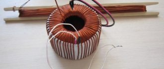
Sometimes in amateur radio practice it becomes necessary to wind a large number of turns of wire to create transformers, chokes, coils and similar winding products. If we are talking about a hundred turns there are no special problems; it is wound using simple mechanical devices. But when you need to wind several thousand turns, and even turn after turn, then you think about automating this very tedious process.
The device in question is an automatic winding machine with a winding stacker and a process indication on a symbolic LCD screen. The intelligent core of the device is the familiar ATmega328P microcontroller, located on the Chinese version of the Arduino UNO board. The controller, through a CNC Shield (CNC expansion board), controls the power part of the device, consisting of two stepper motor drivers (SM) based on the DRV8825 chip and two stepper motors 17HS3401 and 17HS4401 (full revolution 200 steps). The HMI consists of a KY-040 rotary encoder module and a 16x2 character display with an HD44780 controller and an I2C bus communication module on a PCF8574A port expander. The circuit receives power from a 220AC-12DC 60W switching power supply.
The microcontroller uses drivers “Z” and “A”; on the CNC Shield, to connect driver “A” to pins 12 and 13 of the Arduino, jumpers D12-A.STP and D13-A.DIR must be installed. We select the DRV8825 operating mode with a microstep of 1/16 by installing jumpers M2 on the board, this means that for one step of the SD (1.8°) it is necessary to apply 16 edges of the STP signal. The installation of DRV8825 modules must be done as shown below.
After installing the SD drivers, it is necessary to set the current limit. When a 12V voltage is connected to the CNC Shield board, but without electric motors, you need to rotate the trimming resistor to set the limit values. We control the current value with a multimeter and by rotating the trimmer with a screwdriver, we achieve voltage values for driver “Z” of 0.68V and 0.52V for driver “A”. These values are directly related to the rated current of the motor. For 17HS4401 In = 1.7A, and for 17HS3401 In = 1.3A. The voltage value in a mode that is gentle for the motor is calculated using the formula Vref = 0.8*(In / 2).
We connect the I2C 1602 LCD to the corresponding pins SCL, SDA, 5V, GND of the expansion board. On the encoder module we add a pull-up resistor R1 10k if it is not there. To eliminate contact bounce, it is necessary to assemble a hardware suppression circuit; it can be designed as a module that complements the KY-040 module as shown below. Low-pass filters on R4-6 and C1-3 eliminate bounce, and Schmitt triggers MC 74НС14N restore the leading and falling edges of the signal.
To connect the encoder to the Arduino, we connect pins X.STEP and CLK, Y.STEP and SW, X.DIR and DT as well as GND and +5V with the corresponding pins of the board.
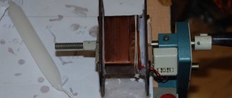
The mechanical part of the winding machine consists of six racks screwed to plexiglass. The stands are printed with plastic on a 3D printer, but if they have the proper straightness, they can be made in other ways and from other materials. The main shaft (M6 pin) is driven by SD 4401 and the winding frame is located on it. Next are two stacker stands with a shaft with a diameter of 6 mm and an M4 pin (thread pitch 0.7 mm) on the SD 3401 shaft. Rotation of the motor leads to linear movement of the stacker, while one step of the SD gives movement L = thread pitch / steps per revolution = 0.7 /200 = 0.0035mm. The last two posts hold the feed reel. Pressing the rubber washer against the bearing ensures tension in the wire during winding.
The program for ATmega328P is written in the Arduino IDE development environment in C++. To successfully compile the code, you must have the LiquidCrystal_I2C library installed.
From the main menu you can get to the submenu for controlling the position of stepper motors POS CONTROL; this is necessary to set the initial position of the main shaft and stacker. The AUTOWINDING submenu is for entering automatic winding values. Work with the encoder button, as well as with the encoder itself and the stepper motor drivers, is carried out through interrupts.
§ 30. Winder of coils of transformers of the 4th category
Characteristics of the work . Winding of coils with a cylindrical multilayer winding from round copper of transformers of the fourth dimension and rectangular copper of transformers of the third and fourth dimensions on horizontal winding machines. Winding of spiral windings over 12 parallels of transformers of the third size and single-pass spiral winding of transformers of the fourth size. Winding of continuous coils for transformers of the first, second and third dimensions. Winding windings on a spatial magnetic circuit. Winding of square windings of dry protective transformers. Winding of disk coils for power and furnace transformers of the fourth and fifth dimensions.
Must know: the design of horizontal winding machines; various designs of transformer coils; device, purpose and rules for using instrumentation and instruments.
Professional ranks
The profession “Coil winder for transformers,” reviews of which are mostly positive, involves career development: the higher the qualification level, the higher the salary. On the path of professional development, a winder can reach 6 categories, each of which has its own features in terms of functionality and requirements.
§ 32. Winder of coils of transformers of the 6th category
Characteristics of the work . Winding of continuous coils of transformers of the fifth and sixth dimensions with switching under load on vertical and horizontal winding machines. Winding of coils of electric furnace transformers and shunt reactors with intertwined winding.
Must know: the structure and principle of control of vertical and horizontal winding machines; methods of winding interlocking coils; requirements for windings and insulating structures.
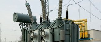
What is a transformer winding machine?
Walking through any populated area, everyone has more than once noticed large iron booths with many wires sticking out of them, and everyone knows that this is a transformer. The quality of electrical energy, the stability of its receipt and the prevention of the risk of short circuits depend on the operation of this mechanism - special elements are responsible for this, the creation of which is the responsibility of the winder. If you understand what kind of work a transformer coil winder does, you can come to the conclusion that these are “invisible” suppliers of safe and high-quality electricity.