Soldering is a reliable and popular method of connecting wires and parts. Knowing how to solder correctly with a soldering iron and having mastered all the intricacies of the process, you can carry out simple work yourself without resorting to the help of craftsmen.
The soldering iron is a traumatic device, so you should be careful when using it.
The subtleties of good soldering
To solder a part to the board, you need:
1) Apply flux to the soldering surface; 2) Tin them with solder; 3) Apply flux to the contacts again; 4) Solder the gap between the contacts.
The first important rule is to avoid temperatures above 400°C or more. Many beginner (and even experienced) radio amateurs neglect this. These are critical values for microcircuits and boards.
Solder melts at approximately 180 to 230°C (lead-containing solders) or 180 to 250°C (lead-free). This is far from 400 °C. Why then set the temperature high?
What you need for reliable contact
Main criteria:
- Choose the right flux. For example, liquid flux is suitable for soldering wires. It wets wires best and allows for better tinning of such contacts. Low-quality flux quickly boils and spreads over the board.
- Use high quality solder. It is the solder that determines the further reliability and strength of the connection. Also, the quality of the solder can affect the operation of the circuit as a whole; due to slag and low-quality alloys, interference may occur in the operation of the electronics and, over time, cracks may appear.
- Use proven tools and equipment. Soldering irons of poor quality can maintain temperature unstably and overheat.
- Maintain temperature conditions. Do not overheat the parts and stay within the melting temperature of the solder. The temperature is too low and the solder will not melt well, and if it is too high, the material will evaporate, making it worse to tin the contacts.
- Long hours of practice, trial and error. Without practice, there will be no soldering method.
These criteria are interrelated with each other. And with a poor choice of components and materials, the same result will occur.
Selecting the power of the soldering iron
The power of the soldering iron must be selected based on the specifics of the work:
- From 20 to 50 W – for circuit boards, small electronics and thin wires;
- 100 W – for copper layers up to 1 mm thick;
- From 200 W – for large parts and wires.
The power is always indicated on the device packaging. In most models it is also indicated on the handle.
Where to begin
First, you need to decide for what purpose you need soldering. For amateur radio, this is an entry-level level; for soldering wiring and a simple level, more professional tools are needed. And to repair and solder SMD and BGA microcircuits, you will have to learn all the basics of soldering and purchase special tools and consumables.
Choosing the Right Soldering Kit
Solders come in different types and diameters.
A large solder diameter is convenient for soldering wires, and small diameters are suitable for spot soldering SMD components or connectors. Solders also come with or without rosin. With rosin, solder is very convenient. It is easiest to use it on a soldering iron tip.
Starter Kit
For radio amateurs, stores sell everything at once in one pack. Such sets are the cheapest, since everything will cost more separately. For example, there are sets with a soldering iron and tips, as well as tweezers.
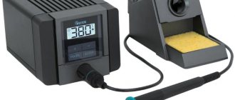
Soldering iron or station
For soldering radio components and wires, a simple soldering iron with a copper tip is sufficient. But for more advanced soldering you will need a station. A soldering station usually consists of a hair dryer and a soldering iron. Using a hair dryer, you can solder SMD components, and you will be able to warm up the board better.
It is best to start with a soldering iron and choose one that has temperature control and changeable tips.
Soldering iron tips
There is an arsenal of tips for soldering irons. Cone, flat, hatchet, wave, etc. They can all be of different sizes and shapes.
Soldering tip selection
A mini wave is perfect for beginners. This type of tip is the easiest to tin and is capable of a wide range of tasks.
Features of application
For soldering wires these are massive tips, and for planar contacts these are usually conical and curved tips. For example, to solder a cable from a board, a hatchet is best suited. This type has a wide working surface, which allows you to massively heat a large surface of the board.
Eternal stings and rules for their use
The main rule when using permanent tips is that there should always be solder or flux on the tip. If you ignore this rule, black dots will begin to appear on the sting, which will eventually spread to the entire surface.
This is a layer of soot that forms when air oxidizes on the working surface. Solder or flux perform a protective function, and during operation of the soldering iron they, and not the soldering iron tip, are oxidized.
Why did the soldering iron start to solder poorly?
If the soldering iron melts the solder, but does not take it to its working surface, then it needs to be tinned. It is highly oxidized, but should not be thrown away.
Preparing for work
After turning on the soldering iron, you need to wait for it to heat up. All preparation comes down to cleaning carbon deposits from the working surface and applying solder. When working with stings, do not use cutting tools. Do not remove carbon deposits from the soldering iron with blades or other sharp objects.
Soldering iron tinning
Tinning a soldering iron occurs in stages:
- The heated tip needs to be cleaned. Using a wet sponge or copper shavings.
- Solder was applied to a clean surface.
The black surface of the tip is removed by long tinning. This is done using a lump of solder and flux. The tip is drowned in solder until it is clean. Periodically it should be dipped in solder. And then clean again with a sponge. In this case, it is best to use copper shavings; they remove oxides and carbon deposits much better. A wet sponge only removes solder, not carbon deposits. If the above methods do not help, then you will have to use a tip activator or soldering acid.
Hair dryer nozzles
The soldering gun also has its own attachments. They come in different diameters, shapes and fastenings. It all depends on what kind of work is being done.
Soldering flux selection
Soldering work has a wide range. And different tasks require different materials. For example, for soldering wires, nothing beats regular rosin. Rosin is cheap, practical and easy to use. But for microcircuits a different approach is needed. Paste-like flux and syringe for precise dosing of flux to SMD components.
How to clean flux after soldering
Using Galosh gasoline or alcohol. Tools and consumables for cleaning:
- Cotton wool;
- Cotton pads;
- Cotton sticks;
- Toothbrush.
Workplace and additional tools
A wooden table is suitable for the workplace. If you don’t want to spoil the surface of the table, you can use a wooden plank. Wood absorbs little heat and does not act as a radiator. And if you don’t have such a board, you can purchase a silicone heat-resistant mat. This mat has a convenient area for disassembling electronics, various pockets and places for tools. The mat can be cleaned with regular alcohol after use if there are any stains or traces of solder.
Tweezers and spatulas
Using tweezers, you can move parts when soldering, position and install parts. They are also made from different materials, they can be angular, straight, with fixation, etc.
Optics and microscopes
Magnifiers are not very convenient, so it is much more convenient and practical to use microscopes. It's best to start with a budget option. For example, a simple USB microscope will allow you to evaluate the result of soldering on a computer screen.
Of course, the frame rate does not allow you to work normally under it, but it allows you to examine small details of the board without harm to your eyesight.
Room ventilation and safety rules
The room must have good ventilation. When soldering, you need to keep your distance and not get too close to avoid solder getting on your face. After soldering work, be sure to ventilate the room and wash your hands and face with soap. You should not eat food while soldering, because smoke residues remain on mucous surfaces.
Precautionary measures
This is the most important part to start with. Some points were indeed mentioned throughout the article - they will be described in more detail here. Plus other rules.
- Hold the soldering iron strictly by the handle.
- Handle parts exclusively with pliers or tweezers. This way you will save not only yourself, but also the parts, because there may be skin discharge (oil or sweat) or static electricity on your fingers.
- Do not look at the board at a right angle. This is not only a matter of vision, but also of solder and flux vapors. The fumes rise, and if you inhale them, you can develop respiratory illness. You can buy or make a homemade hood - just take a 12-volt computer cooler and a power source.
- Ventilate the room in which you solder. Vapors can stick to furniture or clothing. Therefore, it is better not to solder in the bedroom, nursery or kitchen. If there is no space in your apartment, find a corner by the window.
These were a few basic rules that must always be followed.
Simple soldering of wires
The first example is soldering wires.
What you need
To strip the insulation from the wires you will need a stripper.
It can be used to quickly remove insulation. Side cutters, wire cutters, a knife, teeth or a soldering iron will not be able to cope with this task as easily.
Liquid rosin, or FKET, is suitable for soldering wires.
Liquid rosin best coats the wire veins. It is cheap, practical and convenient.
Which sting is better to choose
Wires require a lot of solder. A mini wave is more practical for soldering any wires than a regular cone or flat tip.
Step by step process
We remove the insulation with a stripper and twist the wires.
We apply flux to the wires to be soldered, and take the solder onto the tip. The temperature of the tip is no more than 300 °C.
With several movements back and forth we tin the twisted wires. If the solder has formed into lumps, then add it and wait for the soldering area to cool down so as not to damage the brush. Add more flux and run the soldering iron over the soldering area again. There should not be much or little solder.
It's best to tin both wires before soldering them together, but you won't be able to twist them together securely. Therefore, it is easier to immediately twist and then solder them.
Headphone repair
The main problem when repairing headphones is the resistant insulation of the wires.
Features of wire tinning
To tin such wires, you need to carefully walk over the soldering area using solder and rosin. For soldering you will need a massive tip, a large drop of solder and liquid rosin. Flux is applied in the same way, but soldering is a little different. Now the main task is to burn the insulation. This can be done with a large drop of solder. Using longitudinal movements back and forth, apply solder to the soldering area. Insulation burns slowly. There is no need to raise the temperature above 300 °C or use acid. If we can’t tin, then we try again, but instead of rosin we use LTI-120. This flux will help tin the wires no worse than soldering acid.
Accessories necessary for soldering and desoldering
A soldering iron is a tool used for soldering. A soldering iron consists of a handle and a tip that heats the solder. The tip is very hot, be careful not to burn yourself or accidentally set fire to surrounding objects!
Soldering iron
Solder is most often made from tin and lead, which melts at 185 C. But recently, due to restrictive lead-free environmental standards, a tin-based alloy with an admixture of silver, copper, bismuth or antimony has been used, which has led to significant increasing the melting temperature to 220 C, and therefore it became more difficult to solder it with a “regular” soldering iron. Fortunately, tin and lead solders are still available.
Solder
Rosin is an easy-to-melt resin that makes soldering easier because the tin flows better over surfaces. Rosin dissolves well in alcohol, for example in salicylic alcohol - you can use it and dissolve the resin, and then carefully apply it with a brush to the board that you will solder, and thereby make the work much easier.
Rosin
Tin suction device (also known as a tin pump or extractor) - used to suck out excess molten solder. This is a simple syringe tool consisting of a piston, a spring and a receptacle for suctioned solder. It has a replaceable suction tip on one side, a handle on the other, and a release button on the side.
desoldering pump
Soldering braid is braided copper wires that, when applied to hot tin on soldered elements, absorb the excess.
Solder braid
Pliers - they are used to cut off the legs of the soldered elements (you can use ordinary cosmetic pliers, but they get damaged quite quickly).
Nippers: a) ordinary; b) cosmetic
Other soldering supplies:
Flux - simplifies soldering by removing impurities from the soldered surface, facilitates melting, and increases the fluidity of tin. Flux, unlike rosin, does not leave brown marks, but flux residues must be removed (for example, with acetone) as they can cause corrosion.
Soldering flux
Tweezers - makes it easier to hold a small soldered element, since if you hold it with your hand, you can get burned.
Tweezers
Cleaner - for cleaning the hot tip of the soldering iron from tin residues and other contaminants.
Tip cleaner
The following are photos of different types of universal circuit boards - single-sided and double-sided:
Universal boards: a) single-sided - solder points on one side only; b) double-sided - solder points on both sides
Tinning of enameled wire
Enameled copper wire has a heat capacity and is difficult to tinning. But it can be easily tinned using ordinary rosin. Sandpaper is enough. We remove the enamel coating using sandpaper, apply rosin and the wire is successfully crimped and ready for soldering.
Where to learn to solder
You can train at home by soldering ordinary electrical wires. The main thing is to follow the safety instructions.
The work may require:
- soldering iron (according to professionals, to work with small wires in electronics and radio engineering, a tool with a power of 20-40 W will be sufficient);
- pliers;
- knife;
- scissors;
- set of files;
- sandpaper;
- insulating tape;
- rosin;
- solder.
The question “how to learn to solder” will be resolved after several training sessions. The beginner will gain confidence and experience. Step-by-step soldering instructions can help him with this.
Soldering LED strip
The LED strip has the same heat capacity as a thick wire. It contains a copper substrate, which absorbs heat when heated. We tin the contacts using rosin. We use a mini wave and very little solder. There should be some solder at the soldering site.
Next, we take the soldering iron away from us with the handle, lean the wire against the contact and on top with the tip of the soldering iron. Soldering should take no longer than a second while there is flux. This is due to the fact that the copper substrate quickly absorbs heat, and the burning flux is no longer able to assemble the solder into a single whole. Therefore, if soldering work lasts more than a second, then there will be lumps of solder on the tape with signs of cold contact. If this happens, apply flux again and correct the bad soldering with one touch. Rosin (flux) can be cleaned from the tape using alcohol (or gasoline) and a cotton pad.
Description of the pulse soldering iron.
Pulse soldering iron (Fig. 1)
Nowadays, for some reason this device (Fig. 1) is given the name “Pulse”, but it would be more correct to call such a soldering iron “Transformer”, since its operation is based on a transformer. A distinctive feature of this soldering iron is its design in the form of a gun, as well as the presence of an on/off button. Therefore, the power supplied to the heating element can be adjusted. Additionally, it is worth noting that this soldering iron has a fast heating time, which significantly increases ease of use and speed.
Educational program for beginners
To desolder a part from a board, you need to make sure that the contacts are heated until the solder melts (approximately 230 °C). The main mistake beginners make is to immediately heat the place where they are soldering to 300 - 350 °C.
For example, you need to desolder a microcircuit from a board using a Lukey 702 soldering station.
Many radio amateurs and electronics engineers set heating parameters above 300 °C.
At the first moment, the part is exposed to about 200 °C. The contacts and the surrounding area of soldering work are at room temperature.
The heating of the part reaches 300 °C, but the contacts have not yet reached 200 °C.
The microcircuit experiences a critical temperature of 350 °C. Meanwhile, the surrounding soldering area is heated unevenly, even if the hair dryer is evenly moved across the soldering area. A noticeable temperature difference appears at the contacts of the part.
400 °C and the microcircuit begins to fry.
A little more, and it will unsolder due to the fact that the contacts have practically heated up until the solder melts. But this happens because the board has warmed up. And in this case, it happened unevenly. High temperatures lead to thermal breakdown of the microcircuit and it fails. The board bends, turns black, and bubbles appear due to boiled PCB and its components.
This soldering method is very dangerous and ineffective.
How do you solder parts without damage?
It is necessary to analyze the soldering area and equipment:
- Estimate the thickness of the board. The thicker the board, the more difficult and longer it takes to warm it up. The board consists of layers of tracks, masks, pads and many metal parts that are very heat-intensive.
- What's nearby? To avoid damaging surrounding components, they must be protected from temperature. The following will cope with this task: thermal tape, aluminum tape, radiators and coins.
- What is the ambient temperature ? If the air is cold, the board will have to be heated a little longer. Of particular importance is what is located under the board. No need to solder on a metal plate or on an empty bench. A wooden board or a set of napkins works best. And at the same time, the board must be in the same plane, without distortions.
- Equipment. Many soldering stations are sold without calibration. The difference between the temperature shown on the indicator and the actual temperature can reach either 10 °C or 50 °C.
Security measures
It is important not only to know how to work with a soldering iron, but also to study the safety measures when using it, since their implementation allows you to:
- protect skin from thermal burns;
- prevent fire;
- protect yourself from electric shock.
Before you start using the soldering iron, the technician needs to make sure that the power cable is in good condition. The sting should not come into contact with objects or leashes.
During operation of the soldering iron, you are only allowed to take it by the handle - holding the switched-on tool by the body is dangerous to your health. During breaks between work, the tool should be placed on a stand.
Important! It is recommended that you undergo training from masters before attempting to do it yourself, so that beginning practice does not result in a number of mistakes.
Knowing how to use a soldering iron, a master will be able to perform any job efficiently. It is important to remember to follow safety precautions, since if used incorrectly, the tool can cause serious harm to health.
How to solder with a hairdryer correctly
It is necessary to cover all small components that are vulnerable to overheating with protection. In this case, aluminum tape is used. It protects components well from temperature and holds board components tightly. However, it adds heat capacity to the soldering area. Thermal tape also protects well, but sticks to the board less well.
The board is placed on a material that has the least heat capacity and slowly releases temperature to the environment. You can use, for example, a wooden plank. And at the same time, the soldering area should not be inclined.
It is best to apply flux to the contacts. It distributes heat well compared to heated air, but you should not add too much of it. It may boil, hiss, or interfere with soldering.
The first step is to warm up the soldering area. The hair dryer is set to about 100 °C and maximum air flow.
It is necessary to warm up both the part itself and the surrounding soldering area with contacts in a circular motion.
Next, after about a minute, you should gradually increase the heating.
The difference with the contacts will be small. Thus, within a few minutes, increase to 300 °C.
Steps of about 20 - 30 °C for every tens of seconds.
LIST OF MAIN AND AUXILIARY MATERIALS,
approved for use during maintenance or soldering operations
Specific tinning or soldering materials are specified for each product on the process sheets.
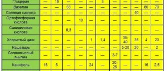
- Solder wire PRv KR1 or PRv KR2 POS 61 GOST 21930-76, Ø 1 mm, Ø2 mm .
- Single-channel tubular solder POS 61T1A GOST 21930-76 , Ø 1 mm, Ø 2 mm.
- Multichannel tubular solder with flux that does not require cleaning , SN62 X39 f. Multicore Solders (based on alloy SN 62, silver-containing), Ø 0.56.
- Multichannel tubular solder with flux that does not require cleaning, SN60 X39 f. Multicore Solders (based on SN 60 alloy), Ø 0.7 mm, Ø 1.2 mm.
- Multichannel tubular solder with flux that does not require cleaning, JM-20 f. Koki (based on alloy SN 60), Ø 0.8 mm, Ø 1.0 mm, Ø 1.2 mm.
- Multi-channel tubular solder with no-clean flux, 60EN Crystal 502 f. Multicore Solders (based on SN 60 alloy), Ø 1.2 mm.
- Multichannel tubular solder with flux that does not require cleaning, CW-801 f. Indium (based on alloy SN 63), Ø 0.8 mm, Ø 1 mm.
- Alcohol-rosin flux FKSp OST 4G 0.033.200 .
- Solid flux “pine rosin grade “A”” GOST 19113-84.
- One-component flux, no cleaning required, X33-12i (MF-210) f. Multicore Solders or WF-9942 f. Indium.
- Ethyl alcohol GOST 18300-87.
- Nefras S2 80/120 TU 38 401-67-108-92
- Flushing liquid VIGON EFM f. Zestron .
- Silver braid for removing solder (outer conductor of radio frequency cable RK-75-1-22 TU 16.505.198-91 ) or copper braid DESOLDERING WICK or similar.
- Round panel brush KFK No. 8, No. 12 GOST 10597-87 .
- Flat panel brush KFP No. 8, No. 12 GOST 10597-87.
- Artistic brush KHZhK No. 1, No. 3 “squirrel” OST 17880-80.
- Cotton scraps art. 361 GOST 4644-75.
- Knitted gloves with polymer coating, type Multex code Per 306 according to catalog f. Tract.
- Antistatic gloves ESD CLOVES 8745 PVCB 6 .
- TTC-LF paste or similar for cleaning and tinning tips.
How to understand that a part is already soldered
A glare appears on the contacts. Using tweezers, gently push the chip. If it moves easily and smoothly from side to side, then it can already be removed; if not, we heat it further.
This technique must be individually adjusted for each soldering and soldering station. For example, sometimes you will have to heat the board longer, and sometimes about 240 °C will be enough. The soldering method depends on the case.
Principle of operation
Soldering iron 12 volt
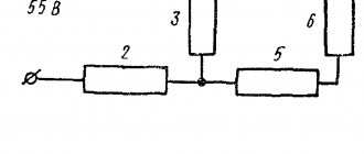
The tip is heated due to the passage of a low voltage current through it. The current-carrying bars are connected to the secondary winding of the induction coil and consist of 2 turns of a metal strip with a cross section of 6-10 mm2. This factor allows the powerful coils and tires to remain cold during operation, while all the heat is concentrated at the end of the tip.
IP's sting
The primary winding is a receiver of mains current with a voltage of 220 V. As a result of induction, a high current and low voltage are excited in the secondary winding. The result of this is the conversion of a powerful pulse of electricity into thermal energy.
A universal soldering tool has its advantages and disadvantages. Analyzing numerous consumer reviews in the media, they can be summarized in two sections.
Alloy Rose
To reduce the risk of overheating, Rose alloy can be used. It will help reduce heat to 120 °C. In this way, you can remove the part from dangerous and sensitive areas. Just add a couple of solder granules and a little flux.
After tinning the contacts, the part is easily desoldered. You need to carefully desolder the contacts; they can easily be damaged due to sudden movement.
The resulting solder must be removed from the board. It is very fragile and not suitable for use.
Flaws
Soldering iron EPSN
Along with the positive characteristics, the disadvantages of IP should be noted:
- When working for a long time, your hand gets tired from having to hold a heavy soldering gun suspended.
- A modern pulse soldering iron with additional options is quite expensive.
Important! Due to the accumulation of high-frequency voltage on the IP tip, sensitive microcircuits can be destroyed during soldering.
Combined method
Another very effective technique. If during soldering the part is poorly soldered or does not desolder, this is a consequence of low-quality solder, flux, or insufficient heating of the board.
To do this, while working with a soldering iron, you need to help from above with a soldering hair dryer. The hair dryer should be set to 200°C. This way, heating will occur faster, and the temperature at the contacts will stabilize, and the surrounding air will absorb less heat.
Why dry chips?
Chips are microcircuits housed in BGA packages. The name, apparently, came from an abbreviation that meant “Numerical Integrated Processor”.
Based on experience, professionals have a strong opinion that during storage, transportation, and shipment, chips absorb moisture and during soldering, it increases in volume and destroys the part.
The effect of moisture on the chip can be seen if the latter is heated. Blisters and bubbles will form on its surface long before the temperature rises to a value sufficient to melt the solder. One can only imagine what is happening inside the part.
To avoid the undesirable consequences of moisture in the chip body, when installing boards, the chips are dried before soldering. This procedure helps remove moisture from the case.
In what cases will soldering with a hairdryer not work?
A soldering gun usually reaches a power of no more than 500 W. The lower the power, the less the board area can be heated.
Using a soldering gun will not adequately desolder massive parts or computer BGA chips (bridges, CPU, GPU). A hairdryer will not be able to warm up such areas.
It's like boiling a glass of water with one match. Increasing the temperature is also not an option; this will destroy both the part itself and the board.
A massive board requires bottom heating. Most often this is a stove that heats up to 100 - 200 °C. The printed circuit board will be heated evenly. And use a hair dryer to bring the solder to melt.
You can also use a hair dryer. It has a larger nozzle and its power can be up to 3000 watts. However, a hair dryer is not a solution either. Due to the fact that only the part and a small surrounding space around it are heated, after soldering the board is deformed due to the high heating difference, thereby tearing off the leads from the pads (this is especially true for large BGA parts).
Application area
A pulse soldering iron (IP) is used for mounting and dismantling components and assemblies of electronic and electrical equipment. The working body of the IP is made of copper wire in the form of an elongated curved loop. The tip is convenient for soldering radio components, wire connections, and can also be used to tin small areas on radio circuit boards.
A comfortable handle and a fairly large tip extension allow you to work in hard-to-reach soldering areas. Due to the heating element quickly raising the melting temperature of the solder, a pulse soldering iron can perform large volumes of work in a short time. This quality of the device is used when unsoldering connectors on the laying of electrical networks, installing light fixtures inside buildings and structures.
Soldering parts from boards with one soldering iron
Small-sized SMD parts can be desoldered using a conical tip. Both contacts of the part heat up and it quickly comes off the board. Also, a conical tip is convenient when soldering SMD parts, since you can accurately dose the amount of solder onto the contacts.
Braided soldering
Braid consists of strands of thin copper wires.
You can use shielding insulation from the antenna as a braid. Using a braid, you can quickly and easily remove solder from a contact. It is necessary to apply flux to the braid and contact. Next, using a soldering iron, the soldering area is slowly heated and the tin is transferred to the braid. This soldering method is good for small parts and small DIP contacts. If you need to unsolder the PCI connector, then the braiding will quickly be wasted.
Vacuum syringe and needles
The vacuum syringe quickly removes massive burnt parts of solder. And with the help of DIP needles, the contacts are easily unsoldered from the board. The needle is put on the contact and heated up using a soldering iron. You need to have time to pass the needle through the board contact onto the microcircuit body while the solder is in a molten state. Or vice versa, when the contact is already warmed up, and at the same second the needle is inserted.
Such soldering methods are outdated. Modern boards are manufactured for machine assembly, so the gap between the contacts and pins of the parts is minimal. The needle is already weak, and the vacuum syringe does not have time to pick up the sharp drops of solder. It is no longer possible to desolder a regular electrolytic capacitor using a syringe. In this case, the liquid sting method will help.
Liquid sting and its advantages
The liquid tip is a drop of solder, which allows you to avoid using additional tools (braid, hair dryer, needles or syringe). The technique is the same as with the Rose alloy. The main difference is in temperatures. The hatchet-type sting has a massive longitudinal working surface. It allows you to capture multiple contacts at once.
Apply solder to the tip. A paste-like flux is applied to the chip to be soldered using a syringe.
The part and its contacts are heated with a sting until the tin melts, and the same must be done on the other side.
Using this technique you can also remove DIP contacts.
Solder joint defects
Solder joint defects are considered to be:
- Solder joints with cracks.
- Broken solder joints.
- "Cold" soldering. The term “cold joints” refers to solder joints formed with signs of incomplete reflow, such as a grainy surface appearance, an irregular joint shape, or incomplete fusion of solder particles.
- The solder fillet violates the minimum electrical clearance between pads or leads of a component, or touches the component body. Solder fillet - the surface formed by solder during the soldering process
- Lack of wetting or poor wettability of a contact or pad - lack (full or partial) of the ability of a pad or plated contact of a component to be wetted by molten solder, reducing the area of the pad or lead covered by solder.
- Solder jumpers between connections, unless electrical contact between these connections is required by the product design
Criteria for assessing the quality of solder connections of lead components mounted in the mounting holes of the board
Contact angle between solder fillet and PCB pad
A sign of a good solder joint is the presence of low or zero contact angles (Ө) between the solder fillet and the pad (angle Ө less than 90˚). The solder fillet is concave; the solder on the attached element forms a frozen seam.
A sign of a poor-quality solder joint is the formation of a solder fillet with a contact angle ( Ө) equal to or greater than 90˚.
Defect – for classes 1, 2, 3:
● Unsoldered – The solder formed a bead on the surface similar to what water forms on a waxed surface. The solder fillet is convex, the contact angle ( Ө) is greater than 90˚,
the frozen seam is not visible. (Reject - marriage).
Protrusion of leads above the board pads
The protrusion of the leads should not lead to violation of the minimum electrical clearance, damage to solder joints due to deformation of the leads, or penetration of the leads through the protective antistatic packaging (film) during subsequent operations or during operation of the product.
The leads protrude above the contact pad in the range from Lmin to Lmax of Table 1, unless there are special requirements in the design documentation.
Table 1. Lead protrusion
| Class 1 | Class 2 | Class 3 | |
| Lmin1 | The end of the lead is visible in the solder 2 | ||
| Lmax | No risk of short circuits | 2.3 mm | 1.5 mm |
Note:
1 For single-sided boards, the lead or wire protrusion (L) is at least 0.5 mm for classes 1 and 2. For class 3, there must be sufficient lead protrusion to differentiate.
2 For boards thicker than 2.3 mm with metallized mounting holes, the protrusion of component pins in DIP packages, sockets, and connectors with fixed-length pins may not be obvious.
Defect – for class 3:
The protrusion of the leads does not meet the requirements of Table 1.
Filling the plated mounting hole of the board with solder and wetting the lead and the walls of the hole with solder
When installing lead elements into through metallized holes, the solder must well wet all contact surfaces, wetting the walls and filling the hole with solder must comply with the drawing and the requirements of Table 2:.
1 - Height of filling the hole with solder. 2 - Component installation side. 3 - Soldering side.
Table 2. Soldering of lead components into metallized holes, minimum acceptable quality criteria for solder joints.
| Parameter1 | Class 1 | Class 2 | Class 3 | |
| A | Circular solder wetting of the component lead and the board pad on the component mounting side | Not regulated | 180˚ | 270˚ |
| B | Solder hole filling height 2 | Not regulated | 75% | 75% |
| C | Circular solder wetting of component lead and board pad on solder side | 270˚ | 270˚ | 330˚ |
| D | Area of contact pad wetted by solder on the installation side of the component | 0 | 0 | 0 |
| E | Area of contact pad wetted by solder on the soldering side | 75% | 75% | 75% |
Note:
(1) Refers to the solder applied during the soldering process.
(2) The unfilled 25% of the hole height includes the unfilled solder cavities on the solder side and on the component mounting side, that is, on both sides of the board in total.
Please note: Some product applications may require the mounting hole to be 100% filled with solder. This condition must be additionally specified in the technological process.
Defect – for classes 1, 2, 3:
solder connection does not comply with table 2.
Vertical filling of the mounting hole with solder:
Standard – for classes 1, 2, 3:
100% wetting of the lead, contact pads and walls of the metallized mounting hole with solder, completely filling the mounting hole around the lead with solder:
- component output;
- solder;
- contact area;
- mounting hole wall;
- PCB solder mask;
- base material of the printed circuit board (pressed layers of fiberglass impregnated with epoxy resin, laminated with copper foil);
- metallized conductive layers of a multilayer printed circuit board.
Acceptable – for classes 1, 2, 3:
at least 75% of the height of the mounting hole cavity is filled with solder; it is allowed that the height of the hole not be filled with solder by 25% (in total on both sides of the board):
Defect - for classes 2, 3:
The vertical filling of the hole with solder is less than 75%.
Peripheral (circular) solder wetting of the lead and the wall of the mounting hole on the solder side
Acceptable - for class 3:
At least 270˚ (3/4) of the hole diameter, the lead and the wall of the mounting hole are covered with solder.
Defect – for class 3:
Less than 270˚ (less than ¾) of the hole diameter, the lead and the wall of the mounting hole are covered with solder.
Solder wetting the annular pad of a plated mounting hole on the mounting side of a component
Acceptable – for classes 1, 2, 3:
The pad on the mounting side of the component may not be covered with solder.
Solder wetting the annular pad of a plated mounting hole on the solder side of a component lead
Acceptable - for classes 1, 2:
at least 270˚ (¾) along the diameter of the mounting hole, the solder fillet covers the ring pad, the walls of the hole and the lead.
Acceptable - for class 3:
at least 330˚ across the diameter of the mounting hole, the solder fillet covers the ring pad, the walls of the hole and the lead.
Acceptable – for classes 1, 2, 3:
Solder wets at least 75% of the ring pad area of the mounting hole.
Distinction of the end of the lead in the solder
Acceptable - for classes 2, 3:
the fillet is convex; the end of the lead is indistinguishable due to excess solder, but the presence of a lead in the hole on the installation side of the component is visually determined.
Defect – for classes 1, 2, 3:
the end of the lead is indistinguishable due to excess solder; from the component installation side, the lead is deformed and it is not obvious that the end of the lead is completely inserted into the mounting hole.
Solder on the molded part (on the bend, “shoulder”) of the component lead
Acceptable - for classes 1, 2, 3:
Solder has flowed onto the lead bend but is not touching the component body.
Defect – for classes 1, 2, 3:
Solder has flowed onto the “shoulder” of the lead and touches the component body.
Additional training
For additional training, you can try soldering various unnecessary boards from computers and smartphones. There are many SMD and DIP components on motherboards. Only long and hard hours of practice will help you develop your soldering skills.
Net
As an exercise, you can try soldering a grid of wires. The quality of soldering is assessed by the load on this soldered wire mesh. If the solder joints do not break under load, then the soldering is excellent.
Constructors
Radio designers are also a great help.
They teach you to understand electrical circuits and the intricacies of soldering. You should start with simple constructors, such as flashing lights or door locks. As your skill increases, you can increase the level of difficulty, reaching complex LED cubes.
Soldering with acid
Acid is used only as a last resort, when a heavily oxidized surface cannot be tinning. All parts, wires and connectors can be perfectly soldered without acid. More about soldering acid
Bottom line
Despite the abundance of theoretical advice, only practice will help you learn how to solder correctly. Take a faulty circuit board from any electronics, remove and solder the components several times. The same applies to splicing wires. A couple of meters of used wiring is enough to get practical experience. Then start the real work.
Sources
- https://www.rmnt.ru/story/instrument/kak-pravilno-pajat-pajalnikom-instruktsija-dlja-chaynikov.1256556/
- https://FB.ru/article/253821/kak-nauchitsya-payat-poshagovaya-instruktsiya-osobennosti-i-rekomendatsii-professionalov
- https://svarka-master.ru/pajka-dlya-nachinayushhih-ot-a-do-ya/
- https://HouseDiz.ru/kak-payat-payalnikom-pravilno-instrukciya-dlya-novichkov/
- https://vopros-remont.ru/elektrika/pajka/
- https://ProFazu.ru/elektrooborudovanie/samodelki-oborud/kak-pravilno-payat.html