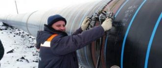
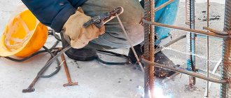
The non-destructive testing laboratory of the Olimp IC carries out vacuum-bubble testing of welds, heat-affected zones, and base metal. The service is provided in Moscow and throughout Russia.
NDT specialists can visit the site the next day after receiving the application. Tests and measurements are carried out by employees certified to qualification levels II and III.
Rostechnadzor and other regulatory agencies trust the conclusions on the compliance of the inspection object with the requirements of technical documentation issued by LNK.
Find out the cost of the service - send a request
Non-destructive testing laboratory
Non-destructive testing laboratory
Vacuuming of welds
Evacuation of tanks is used to test welded joints and base metal for leaks.
Vacuuming (general definition) is the removal of gas, steam or a vapor-gas environment from vessels or apparatus in order to obtain a pressure below atmospheric in them.
Leak detection
Leak detection is a set of means, methods and techniques for detecting leaks and establishing the degree of tightness of vacuum systems. The place where the integrity of the shell is damaged is called a leak. These are usually micropores in the shell material itself and in welds, marks on the working surface of flanges and metal seals, forming a through channel with an exit to both sides of the shell. The size of the leak, as well as the degree of tightness, is characterized by the air flow flowing through the leak per unit of time under normal conditions.
Ultrasonic testing
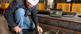
Ultrasonic testing is one of the most popular non-destructive testing methods that uses ultrasonic waves to detect defects in materials.
In order to improve the quality and reliability of production in various sectors of the national economy: energy, metallurgy, heavy and chemical engineering, railway transport, shipbuilding, gas pipeline construction and other industries, non-destructive testing is carried out. Ultrasonic testing is the most popular method of obtaining information about defects located at significant depths in various materials, products and welded joints.
The combination of a number of properties characteristic of ultrasonic non-destructive testing makes this type of testing practically irreplaceable in many cases. This method is a preventive measure for predicting and preventing malfunctions, emergency failures of machines, mechanisms, metal structures, oil and gas supply pipelines, vessels and apparatus operating under high pressure, forgings, rolled sheets, pipes and other types of products. This work is performed by defect detection operators.
Ultrasonic testing of welded joints is carried out in accordance with GOST 14782-86 “Non-destructive testing. Welded connections. Ultrasonic methods" and allows you to carry out ultrasonic diagnostics of the quality of welded joints, identify and document areas of high defect content, classifying them by type and size era. For different types of welded joints, appropriate ultrasonic testing methods are used. Conducting an ultrasonic inspection is necessary to undergo an examination of projects for redevelopment and addition of building floors, assessing the load-bearing capacity of metal structures and their wear. For ultrasonic testing of welded joints, echo-pulse, shadow or echo-shadow ultrasonic testing methods are used.
A significant role in the objectivity of the obtained results of the work of the flaw detector operator is played by his qualifications, theoretical training and practical training skills. To increase the objectivity of the picture of the quality of a product or welded joint, automation of ultrasonic testing is being introduced, which also increases labor productivity. Ultrasonic testing is a set of special methods that involve detecting defects in solid material, such as cracks, pores, scratches, etc. using ultrasound. In general, ultrasonic testing determines the properties and parameters of an object, which are mainly responsible for the reliability of operation. Most often, ultrasonic testing is carried out on welds, as well as on those types of structures whose defects can lead to failure of the entire structure. Ultrasonic testing today is very common among manufacturers of those elements and structures that ensure the normal functioning of the population or the normal functioning of an enterprise. This method of flaw detection uses the property of solid materials in the presence of air cavities, rust, cracking and other defects to send vibrations under the influence of ultrasound. Our company provides high-quality ultrasonic testing services; our technicians are very highly qualified and use only high-quality equipment in their work. That is why ultrasonic testing is successfully used in almost all areas of industry today.
Penetrant flaw detection
Penetrant flaw detection is designed to detect surface and through defects in test objects, determine their location and extent (for extended defects such as cracks).
In most cases, according to technical requirements, it is necessary to identify defects so small that it is almost impossible to notice them during a visual inspection with the naked eye. The use of optical instruments, such as a magnifying glass or microscope, does not allow identifying surface defects due to insufficient contrast of the image of the defect against the background of the metal and a small field of view at high magnifications.
In such cases, the most applicable is the capillary control method.
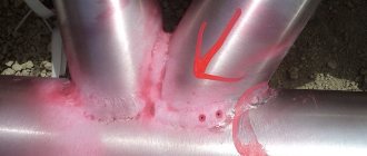
Penetrant flaw detection is based on the capillary penetration of indicator liquids into the cavities of surface and through discontinuities in the material of objects under control and recording the resulting indicator traces visually or using a transducer.
Penetrant flaw detection is designed to detect surface and through defects in test objects, determine their location, extent (for extended defects such as cracks) and orientation along the surface.
Penetrant flaw detection allows you to control objects of any size and shape, made of ferrous and non-ferrous metals and alloys, plastics, glass, ceramics, as well as other solid non-ferromagnetic materials.
Penetrant flaw detection is used to control objects made of ferromagnetic materials if their magnetic properties, shape, type and location of defects do not allow achieving the sensitivity required by GOST 21105-87 using the magnetic particle method and the magnetic particle testing method is not allowed to be used due to the operating conditions of the object.
A necessary condition for identifying defects such as a violation of the continuity of a material by capillary methods is the presence of cavities that are free from contaminants and other substances that have access to the surface of objects and a depth of distribution that significantly exceeds the width of their opening.
Capillary methods are divided into basic, using capillary phenomena, and combined, based on a combination of two or more non-destructive testing methods of different physical nature, one of which is capillary.
The main capillary control methods are classified:
- depending on the type of penetrating substance: penetrating solutions, filterable suspensions;
- depending on the method of obtaining primary information: brightness (achromatic), color (chromatic), luminescent, luminescent-color.
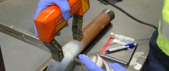
Magnetic particle flaw detection
Magnetic particle flaw detection (MPD) is designed to detect subtle surface and subsurface discontinuities in metal—defects that extend deep into products. Such defects can be cracks, hairlines, tears, flakes, lack of penetration, pores. In Russia it is quite difficult to find an organization that professionally deals with magnetic particle testing, which is necessary for checking metal structures.
How does magnetic particle testing work? The prepared surface of the product is magnetized, a magnetic suspension is applied to it, which quickly accumulates on the inhomogeneities of the magnetic field in the defect zone, displaying the location and contour of the defects. Please remember that not all items should be tested using magnetic particle inspection. Check out the sections on X-ray testing and liquid penetrant testing for more information on non-destructive testing, or contact our specialists.
When should magnetic particle inspection be used? The greatest probability of detecting defects is achieved when the plane of the defect makes an angle of 90 degrees with the direction of the magnetic flux. As this angle decreases, the sensitivity of the method decreases, and at angles significantly smaller than 90 degrees, defects may not be detected.
Mechanical tests
Mechanical tests determine the strength and reliability of welded joints. The main methods for determining the mechanical properties of a welded joint and its individual zones are established by GOST 6996-66 “Welded joints. Methods for determining mechanical properties." It involves static and impact tests at normal, and in some cases at low or high temperatures.
For welded joints of critical structures made of high-strength materials or intended to operate under conditions of negative temperatures and vibration loads, additional tests are carried out for resistance to brittle fracture and fatigue strength.
Mechanical tests, according to the nature of the loading, are divided into: - static, in which the force gradually increases or remains constant for a long time; — dynamic, in which the force increases almost instantly and does not last long; — fatigue, in which the load changes repeatedly (from tens and millions of cycles) in magnitude and sign.
Radiographic (X-ray) control
Radiographic (X-ray) control can rightly be classified as a rapidly developing control method aimed at limited access. The most common application for X-ray inspection is in the electronics industry. It should be especially noted that defect coverage by X-ray inspection successfully complements and only partially duplicates standard in-circuit inspection methods. Not so long ago, X-ray inspection systems were used only in laboratories, but the intensive development of industry and new technologies has made it possible to use them on production lines. It was thanks to the use of X-ray inspection systems that it became possible to study invisible compounds in PU.
Main capabilities of radiographic testing:
- The ability to detect defects that cannot be detected by any other test - for example, missing solders, sinkholes and others;
- Regardless of access, coverage of technological defects is at least 97%;
- Automatic X-ray inspection systems can be used on various production lines;
- The ability to accurately localize detected defects, which makes it possible to quickly repair.
Carrying out flaw detection using X-ray scanning of metal is the most reliable way to control welded joints and base metal when inspecting pipelines, equipment, and conducting electrical inspection. X-ray testing is based on the absorption of X-rays, which depends on the density of the medium and the atomic number of the elements forming the medium material. The presence of defects such as cracks, pits or inclusions of foreign material causes the rays passing through the material to be attenuated to varying degrees. By recording the intensity distribution of transmitted rays, it is possible to determine the presence and location of various material inhomogeneities. X-ray testing is used to determine cavities, rough cracks, and segregation inclusions in cast and welded steel products up to 80 mm thick and in light alloy products up to 250 mm thick. For this purpose, industrial X-ray installations with radiation energies from 5-10 to 200-400 keV (1 eV = 1.60210 Ç 10-19 J) are used. Products of large thickness (up to 500 mm) are illuminated with ultra-hard electromagnetic radiation with an energy of tens of MeV, obtained in a betatron.
Advantages of X-ray inspection Detection and precise localization of defects, high coverage of technological defects, and the absence of a contact device are the main advantages of X-ray inspection.
Vacuum bubble testing of metal structures
The non-destructive testing laboratory of the Olimp IC carries out vacuum-bubble testing of welds, heat-affected zones, and base metal. The service is provided in Moscow and throughout Russia.
NDT specialists can visit the site the next day after receiving the application. Tests and measurements are carried out by employees certified to qualification levels II and III.
Rostechnadzor and other regulatory agencies trust the conclusions on the compliance of the inspection object with the requirements of technical documentation issued by LNK.
The laboratory is certified to carry out vacuum-bubble testing of the following objects:
- building structures;
- pipelines;
- equipment for hazardous industries;
- boiler inspection facilities;
- gas supply systems;
- oil and gas industry equipment;
- lifting structures.
Vacuuming
The main and only purpose of the vacuum-bubble method is to detect through defects that affect both the current performance of equipment, for example, maintaining tightness, and its future operation. The presence of defects can cause gradual corrosion of objects, a decrease in their strength and electrical conductivity, as well as emergency situations, leaks of chemicals, and so on. Leak detection is widely used in monitoring welds on tank bottoms. When testing using this method, a vacuum chamber is installed on the side of the welded joint being tested, moistened with a foam indicator solution, in which the air becomes rarefied and, thanks to the resulting pressure difference, atmospheric air penetrates through the through defects, forming bubbles. Control is carried out at ambient temperatures from +8ºС to +40ºС and relative humidity no more than 80%.
The procedure for performing the vacuum-bubble method:
- Remove metal splashes, rust and other contaminants from the surface. It is not allowed to apply paint and varnish coatings before inspection;
- Apply a foaming film composition (FPS) to the controlled surface;
- Place a vacuum chamber on top of the PPS and press tightly;
- Create a vacuum in the vacuum chamber of at least 0.08 MPa;
- Allow exposure for at least 20 seconds;
- Inspect the control area located under the frame for indications (foam bubble). If there are indications, mark them next to the vacuum chamber. To do this, it is necessary to visually draw a perpendicular line from the defect relative to the weld. After removing the camera, the markings are transferred to the weld;
- Unload the vacuum system.
The installation for monitoring should include: a fore-vacuum pump, a vacuum receiver, one or a set of vacuum chambers with three-way valves, vacuum gauges and lighting fixtures, hoses.
The vacuum-bubble method can be used at boiler inspection facilities, gas supply systems, equipment in the oil and gas industry, equipment in fire-explosion and chemically hazardous industries.
The OLIMP IC laboratory offers you high-quality work on vacuum-bubble testing by competent specialists.
The purpose of non-destructive testing using the vacuum-bubble method:
- Establish compliance of the survey object with the requirements of regulatory and technical documentation.
- Give a qualitative and quantitative assessment of surface/subsurface defects, determining the degree of their potential danger.
- To increase the level of safety of equipment operation at industrial facilities classified as particularly hazardous.
- Ensure the safe operation of critical pipelines and prevent possible accidents.
- Timely identify unacceptable structural defects at various stages of construction of buildings and structures.
Mobile laboratory of non-destructive testing "SK "OLIMP" is:
- Guaranteed accuracy of results.
- A complete set of verified equipment, certified materials, calibrated control samples necessary to perform all measurements and tests using non-destructive testing methods using ultrasound within the scope of the laboratory certification. Measuring instruments are included in the state register.
- Years of experience in solving non-standard non-destructive testing problems.
- Competent personnel - employees are certified for qualification levels II and III, NDT specialists have more than 10 years of experience.
- An extensive base of regular customers, each of whom is given a discount the next time they contact or order other services of the company.
We have all the permitting documentation in our possession
Get advice from a laboratory technician or submit an application for vacuum-bubble testing.
- Send a message to e-mail: [email protected]
- Call phone numbers 8, 8 (800) 707-72-31 or request a call back.
Pre-evacuation
Pre-evacuation does not completely eliminate capillary forces during the saturation of pores with liquid, since the interface between the saturating liquid and its vapor does not disappear. Capillary forces in a micro-inhomogeneous porous medium can always be the reason for its incomplete saturation with liquid due to the pinching of gas phase bubbles in some pores. Therefore, determining the capacity of pores communicating with the surface of a rock sample using the saturation method is associated in many cases with certain difficulties. [2]
Pre-evacuation is aimed at removing air from the tank and checking the reliability of the vacuum seals. This evacuation helps remove surface moisture from the active part of the transformer, and therefore improves the insulation characteristics. [3]
Pre-evacuation of rubber mixtures during the molding process in worm machines sharply reduces pore formation and allows vulcanization of products without pressure. [5]
The beginning of pre-evacuation should be considered the moment when the full vacuum allowed for a given transformer design is reached. [6]
It is recommended to use preliminary evacuation of the bellows cavities. The liquid being measured is usually used as a reference liquid, the density of which is equal to the lower limit of the measuring range of the transducer. [7]
During the process of preliminary evacuation, the quality of the welds and seals of the transformer tank is revealed, which makes it possible to promptly eliminate detected defects. It takes considerable time to eliminate various air leaks. Sometimes seal failures are so severe that partial disassembly of the transformer is required. [8]
Starting pumps during preliminary evacuation is always carried out with a closed pressure valve or a locked check valve, since in this case it is necessary to create a chamber that is not connected to the atmosphere. [9]
Pre-evacuation is also performed through it. [10]
As shown in [425], preliminary evacuation of products at elevated temperatures, 10 - 20 QC exceeding the upper temperature limit of rubber performance, increases the durability of seals based on hydrocarbon rubbers with a polysulfide vulcanization mesh, but worsens the performance of thiuram vulcanization rubbers, increases the performance of seals based on siloxane rubbers by removing moisture from them. [eleven]
For high-quality filling, it is recommended to use preliminary evacuation of the bellows cavities. A solution of the measured liquid, the density of which is equal to the lower limit of the measuring range of the transducer, is usually used as a reference solution. [12]
The method of impregnation under atmospheric pressure with preliminary vacuuming is based on the introduction of an impregnating liquid into wood under the influence of atmospheric pressure, which is excess relative to the pressure inside the wood. [13]
Vacuum filling consists of three stages: preliminary evacuation of the tank and active part without oil; oil filling under vacuum; Evacuation of a transformer filled with oil. [15]
Seam tightness
#1 Igor 66
#2 svarnoi69
Popular message!
Igor 66 , let me anticipate your technology and offer an overclocked option at least 5-10 times cheaper.
breast pump for nursing mothers
Well, as an option, it is still possible to use a device to increase the length of the penis.
Lubricating the weld seam with a solution for soap bubbles.
- 10
- Top
- Insert nickname
#3 Mengon
“The one who gets up first gets the boots.”
- Top
- Insert nickname
#4 Svinovod
Well, the man was immediately pecked to death. Igor 66, you would sketch out your idea, publish some test results, otherwise there’s really nothing to talk about: people are just joking.
. on the river, on the lake, worked on a bulldozer.
- Top
- Insert nickname
#5 Igor 66
- Top
- Insert nickname
#6 AVN
How about making frames with different radii without going broke on the tooling?
- Top
- Insert nickname
#7 George 11
Please don't be rude to me, otherwise I'll press the complaint button
- Orel city
- Top
- Insert nickname
#8 Svinovod
How about making frames with different radii without going broke on the tooling?
I thought about this too. Perhaps the method is suitable for long seams on flat surfaces. In any case, the method will be of limited use.
By the way, why is this method better than “press-and-wash”?
. on the river, on the lake, worked on a bulldozer.
- Top
- Insert nickname
#9 Georgiy 11
Please don't be rude to me, otherwise I'll press the complaint button
- Orel city
- Top
- Insert nickname
#10 AVN
for long seams on flat surfaces
- Top
- Insert nickname
#11 Svinovod
I understand that this means large containers (and what else cannot be pressed in the usual way.). Actually, I wrote:
The method is suitable for long seams on flat surfaces.
What about fillet seams (and there are most of them)? Here a completely different adaptation is needed. In general, we are waiting for the author’s comments with examples of combat use. And further. The metal surface may be rough or simply poorly processed - there will be problems with suction. Little is clear yet.
. on the river, on the lake, worked on a bulldozer.
- Top
- Insert nickname
#12 Svinovod
Hardly. Imagine a tank, almost rectangular in shape, with dimensions of 12,000 mm x 12,000 mm x 12,000 mm. What’s easier: coat the seams with chalk and kerosene (penetrant developer) or check with a vacuum leak detector?
Yes, but, for example, in the food industry this is hardly acceptable. The idea has the right to life, but implementation is not yet visible.
. on the river, on the lake, worked on a bulldozer.
- Top
- Insert nickname
#13 Igor 66
Attached images
Post edited by Igor 66: 21 September 2015 15:01
- Top
- Insert nickname
#14 Mengon
The idea has the right to life, but implementation is not yet visible.
The idea is old and is being implemented:
Vacuum frames
Vacuum frames
used to control tightness using the bubble method. Inspection allows you to identify through defects in welded joints and main products made of steel and plastic. The frames are used to control objects such as tanks, boilers, pipelines, fuel tanks, linings and other objects with one-way access.
Vacuum frames complete with a portable vacuum leak detector TVP-12 have a test certificate from the Leading Materials Science Organization OJSC NIKIMT-Atomstroy on the possibility of use in monitoring pipelines of nuclear power plants and facilities of other industries. According to test results, the sensitivity of control using vacuum frames corresponds to tightness class IV according to PNAE G-7-008-89 and PNAE G-7-019-89
To test the sensitivity of control using vacuum frames, a mechanical adjustable leak block BT-1 “Expert” can be used.
Depending on the shape of the controlled objects, the following standard types of vacuum frames can be used:
Frame shape
Window dimensions, mm Photo Purpose
Vacuum frame for tightness control flat 530x60
Control of butt welds and flat surfaces Frame for tightness control flat-overlapping 530x60xh8 Control of overlap seams and surfaces with a height difference of 6-10mm Vacuum corner frame 500x60 Control of corners (mornings) and T-welds Vacuum corner frame (external) on request Inspection of external corner (morning) welds Triangular vacuum frame 200x200x200 Inspection of internal welded corners formed by three planes Round vacuum chamber Ø 240 For inspection of flat, convex and concave surfaces Rectangular vacuum chamber 230x230 For inspection flat surfaces Vacuum frame for tightness testing, cylindrical Ø 100 For external testing of triangular angles Vacuum frame for pipes with diameters from 73.6 mm to 1220.0 mm Depends on the diameter Pipe tightness control
Chemical analysis of metals
The testing laboratory of KazPromBezopasnost PV LLP conducts chemical and spectral analysis of rolled metal and metal products made from various grades of steel and alloys.
With the help of modern instruments, our laboratory has the ability to:
— quickly and accurately determine the elemental composition of the metal (alloy);
— determine the grade of material;
— carry out incoming inspection of metal products for compliance of the material with RD.
Only certified analytical research methods are used in accordance with state standards.
The main advantages of using chemical analysis are:
— quantitative determination of chemical elements (carbon, sulfur, phosphorus);
— high measurement accuracy.
The main advantages of using spectral analysis are:
— non-destructive testing method;
— ability to work with samples of any shape and size;
— minimum requirements for sample preparation.
All studies are carried out by highly qualified specialists using certified and verified equipment.
Magnetic flaw detection
Magnetic flaw detection is one of the non-destructive testing methods used to identify defects in ferromagnetic materials (nickel, iron, cobalt and a number of alloys based on them).
Magnetic powder method reveals such defects as: lack of fusion, cracks, non-metallic inclusions, hairs, flakes. Detection of defects is possible if they extend to the surface of the product or are located at a shallow depth (no more than 2-3 mm). Magnetic methods are based on the emission of magnetic fields around the testing site.
Quality control of welded joints
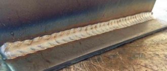
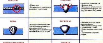
The operational parameters of metal structures are affected by the quality of the material and welds. The lower the degree of welding, the faster the connection will become thinner and the product will fail: it will break, begin to leak, or collapse. Poor quality of welded joints during the installation of pipelines can lead to an emergency situation and serious financial losses for the owner.
| Service No. | Test name | Regulatory document | Cost, rub. |
| Welded joints | |||
| 46 | Quality control (flaw detection) of welded joints (seams) using the ultrasonic method (p.m.) | RD 34.17.302 SP 70.13330 | up to 10 m 2 700 11 - 30 m 2 200 31 - 50 m 1 300 more than 51 m 650 ₽ |
| 47 | Quality control (flaw detection) of welded joints (seams) of pipelines using the ultrasonic method (1 joint) | RD 34.17.302 SP 74.13330 SP 75.13330 | up to Ø50 mm 450 Ø51 — Ø100 mm 650 Ø101 — Ø300 mm 900 more than Ø301 mm 1,100 ₽ |
| 48 | Tensile test of welded joint (1 sample) | GOST 6996 | 3000 ₽ |
| 49 | Visual and measuring control of welded joints (seams) (1 p.m.) | RD 03-606-03 | 100 ₽ |
| 50 | Quality control (flaw detection) of welded joints (seams) by thermal method (1 lm) | RD-13-04 GOST 23483 | 1500 ₽ |
Non-destructive technologies are a suitable method for quality control of welded joints at any stage of production or operation of a structure. This includes a visual inspection. The weak point of this technique is that it will only provide data on the external condition of the scar. Modern equipment and tools allow us to fully assess the condition of the seam throughout its entire depth and not to damage its integrity. The technical equipment that our experts work with allows us to detect even microscopic errors and defects inside the scar.
Ultrasonic (UK)
This method is widely used to control the quality of welded joints. As the name suggests, ultrasound is used for testing - a sound wave with a frequency above 20 kHz (for testing it is used from 200 kHz to 100 MHz). Ultrasound propagates throughout the product in the form of waves that have physical parameters such as:
- wavelength;
- period
- frequency
There are a very large number of ultrasonic (acoustic) testing methods.
Within the framework of the article, we will not dwell on each in detail, but will consider the most common method that is used in practice when inspecting welded joints - the ECM method.
Also very important parameters are the types of waves used.
Waves are of the following types:
- Transverse (shear waves).
- Longitudinal (compression waves).
- Surface (Rayleigh).
- Lamb waves.
- Porchhammer waves.
Ultrasonic testing - control
The principle of using ultrasonic testing is as follows: with the help of a flaw detector, ultrasonic vibrations are created and introduced into the product. Ultrasound, spreading in the product and reaching the defect, is reflected from it. If there are no defects, then the sound wave is reflected from the bottom surface. Depending on the return time and signal amplitude, it is possible to determine the depth of the defect and estimate (compare with acceptable) its dimensions.
Preliminary adjustment of the flaw detector is carried out using reference samples (the so-called SOPs - standard samples of the enterprise), on which the maximum permissible defect is artificially created. If during the inspection process a signal greater than the one that was configured on the SOP is detected, then the products are considered defective.
The following equipment is required for ultrasonic testing:
- flaw detector
- Lemo cable
- piezoelectric transducer (PET)
PEPs differ in:
- input - inclined and straight;
- by structure (design) - combined and separated-combined;
- by type of contact with the surface - non-contact and contact.
Inclined probes are used when you need to look for defects that are not parallel to the surface being tested.
Combined probes use one piezoelectric element that both generates and receives signals.
For separate-combined ones, 2 different piezoelements are used, one of which generates a signal, and the other receives it. In this case, the control accuracy increases.
UT - ultrasonic thickness measurement
Ultrasonic thickness gauging is used to determine the thickness of a part with access from one side. It is often used when assessing the residual life, when it is necessary to measure the wall thickness and the amount of wear.
In ultrasonic testing, a separate-combined probe is used, which is connected by a cable to a special device—a thickness gauge. To carry out UT, it is necessary to establish the speed of sound propagation in the material being measured. The adjustment is made on samples with a known thickness made of the same material that will be tested.
The testing process itself is similar to the ultrasonic testing process, only in this case the transducer is not moved, but is simply pressed against the surface at individual measurement points and rotated by 10-15 degrees.
Useful article - Welding lessons for beginners
Is it possible to save money on laboratory services?
A number of unacceptable defects can be determined independently, based on the standards given in RD 03-606-03. The main provision for specialists is “Instructions for visual and measuring control”. Each construction testing center begins testing work with this method of analyzing the condition of scars. Without resorting to the help of special measuring tools and instruments, you can detect a number of surface defects: violation of the geometry of the seam, the presence of pores, cracks, chips. To prevent the occurrence of such violations, regulatory requirements should be issued to welders so that they can independently carry out simple diagnostics of welded joints after completion of installation work. This way, you will avoid overpaying for additional services.
On the day of flaw detection of welded joints, call a team of welders to the site so that they can promptly correct any detected errors. While experts are examining other areas. Carrying out repeated control on the same day will not require additional payment for laboratory staff visiting the site.
You can independently prepare the object for inspection work:
- Clean the scar from moisture, rust, frozen scale, slag using a grinder or grinder so that the inspector can conduct a visual inspection and capillary examination of the structure. When cleaning, do not use hard wheels or cut off the weld bead.
- Before carrying out ultrasonic diagnostics, the seam should be cleaned of frozen metal splashes, a layer of rust should be removed, and the insulating coating or paint layer should be removed. According to GOST, the roughness of the prepared surface must correspond to Rz 40 µm. It is necessary to provide specialists with access along the entire length of the seam.
- To examine the structure of a weld using X-ray equipment, it is necessary to provide 100% access to the joint from 2 sides and provide a space free of people for working with X-rays. The ideal option is to organize the examination outside of working hours.
To carry out verification work, provide the maximum volume of structures. Thus, you will be able to avoid additional costs by paying the minimum cost for a mobile laboratory to travel to the site.
The large volume ensures a rational distribution of laboratory resources and makes it possible to reduce unit prices for conducting research using non-destructive testing methods.
During the inspection, flaw detectors from the Archibuild laboratory of non-destructive testing of welded joints identify permissible errors and enter them into the research protocol. Such defects are not grounds for prohibiting the delivery of the object. They demonstrate the professional level of welders and reduce the operational capabilities of the product. During use, the structure may be subject to loads, vibrations, and adverse environmental influences; if there are even minor errors, the seam will collapse many times faster.
Leak detection using bubble vacuum method (vacuum) (PVT)
Penetrant control (PVC)
6.2.9.1 PVC is carried out to identify surface defects in welded joints and base metal of tank structural elements.
Flaw detection materials are used in the form of sets in aerosol packages according to the instructions for use. Kits should include:
- indicator penetrant, the characteristic color tone of which can be observed in visible radiation;
— cleaner of the test object from penetrant;
— developer of an indicator trace of a defect.
Compatibility of materials in sets is required. The compositions of the kit must not cause corrosion.
6.2.9.2 PVK is carried out in accordance with GOST 18442 (IV sensitivity class), instructions for the use of flaw detection materials and includes:
a) applying an indicator penetrant to the test surface, which includes the weld and the base metal at a distance greater than the thickness of the test elements on both sides of the seam. The penetrant is not allowed to dry on the surface;
b) removal of indicator penetrant;
c) application and drying of the developer. Drips and leaks of developer are not allowed. Drying of the developer should be carried out by natural evaporation or by blowing with heated air at a temperature of plus (60±10) °C;
d) inspection of the controlled surface is carried out 20 minutes after the developer has dried under illumination of at least 350 Lux. When inspecting the controlled surface, magnifying glasses from 2 x to 7 x magnification are used. If an indicator trace is detected, the identified defect is assessed using VIC. To do this, the area with the mark is marked and the surface to be inspected is cleaned of flaw detection materials. VIC is carried out using magnifying glasses and optical measuring instruments with tenfold or more magnification;
e) the scope of control of pontoons made of aluminum alloys is determined based on the results of the visual inspection, and all areas of the pontoon (seams and base metal) on the outer surface of which the presence of oil is detected must be inspected;
f) the results of the PVK are formalized in accordance with Appendix E.
6.2.10.1 PVT is used to detect through damage (tightness violations) of welded joints of tank structural elements in accordance with GOST 3242.
To carry out leak detection of PVT, vacuum chambers must be used that ensure the creation of a vacuum of at least 0.08 MPa.
6.2.10.2 When carrying out HTP, a vacuum must be created in the chamber for welded joints with the thickness of the elements being connected:
- no more than 4 mm - no less than 0.067 MPa;
- more than 4 mm - not less than 0.08 MPa.
6.2.10.3 Control is carried out in accordance with the operating instructions for the vacuum chamber.
6.2.10.4 During leak detection, foam indicators must be used to ensure leak detection at the evacuation temperature.
6.2.10.5 A leak is determined by the appearance of foam indicator bubbles.
6.2.10.6 HTP is not carried out through a particularly reinforced coating. HTP on damaged coatings of all types that do not meet the requirements of RD-23.020.00-KTN-184-10 is carried out after removing the remaining coating and stripping the structures to metal.
HTP through normal and/or reinforced coatings is carried out according to the results of the VIC.
6.2.10.7 The results of the HTP are drawn up in accordance with Appendix Y. The HTP report is accompanied by sketches of the tank structures indicating the coordinates of the location of the identified through damage (tightness violations).
Date added: 2015-06-04; ; Copyright infringement?
Your opinion is important to us! Was the published material useful? Yes | No
