Club of Defenders of Silence
Today I studied various versions of the old St. Petersburg fund through the website gorod.gov.spb.ru. I found various options for floors: 1. Reinforced concrete prefabricated and monolithic 2. Wooden on metal beams, plastered between floors 3. With brick vaults and concrete filling on metal beams
It often happens that both reinforced concrete and wooden beams on metal beams stand together (apparently mixed).
From this, the question is, what kind of floors are these “With brick vaults and concrete filling on metal beams” and is it possible to live with such? Much worse than monolithic ones?
- Comment
Related documents
- When have requests solved problems?
- Developers of houses made of “honest solid” bricks
- What about them?
Subscribe to comments Comments (12)
I get the impression that the overall thickness of the floors does not make such a huge difference in impact noise. In panels where the walls are as thin as the ceilings (14-16 cm each), and reinforced concrete structures are welded together, such noises come as if through wires. The only thing that can stop the rumble or seriously reduce it is floating floors. I even suspect that with your tent floors and normal floor the sounds were 2 times quieter than mine with 14-16 cm. floors and linoleum on screed.
If the floor is homogeneous (slab), then there may not be much difference. I lived in a monolith, where there was more than 16 cm of flooring, I lived in episode 137 - and in both places I heard walking and some other sounds about the same. There was linoleum on the screed here and there. Now I understand that I probably heard footsteps everywhere periodically, but my brain just filtered them, and they didn’t bother me, because... people walked normally and there were no children. Now I listen involuntarily in all the apartments where I visit relatives/friends - I understand that the walking of the upper ones and their fussing is almost everywhere (in panels/monoliths) on the middle floors, because sound perception is heightened to the limit. But the owners don’t care - they are still healthy and strong-nerved). It is quietest for parents in SF with beam floors. There is a thread here on the forum where the people at the top were forced through court to make a floating floor on the hipped ceilings - of course it became quieter, but the stomping of elephants and falling objects still did not go away. But with the native ZI (floor on joists) there were no such problems.
In terms of impact noise, the uniformity of the panels is very poor. In this design, the sound comes - you're right, as if through wires, without loss. It’s even “better” in a monolith, because There aren't even any joints there at all. Beam floors (not wooden ones) are good precisely because of their heterogeneity - the sound fades, moving from structure to structure. This is what’s good about a brick wall (besides the mass, of course) - there are continuous transitions: brick and mortar. But again, for the millionth time, impact noise does not arise on its own and is generated not by ceiling walls, but by morons, so here it is better to fight not with the effect - the passage of noise through the building structures, but with the cause - the absence of impacts.
I get the impression that the overall thickness of the floors does not make such a huge difference in impact noise. In panels where the walls are as thin as the ceilings (14-16 cm each), and reinforced concrete structures are welded together, such noises come as if through wires. The only thing that can stop the rumble or seriously reduce it is floating floors. I even suspect that with your tent floors and normal floor the sounds were 2 times quieter than mine with 14-16 cm. floors and linoleum on screed.
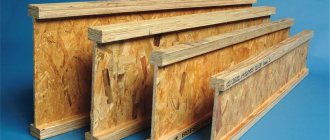
Overlapping on metal beams
To install durable floors in buildings being constructed, builders use proven methods that involve the use of various building materials. An increased margin of safety is provided by profiles made of rolled steel. Floors constructed on their basis on metal beams ensure the reliability of the structures being erected and a long service life. They are superior to structures based on wooden beams in terms of performance and are able to withstand significant loads. Let's look at them in detail.
Structural options for flooring on metal beams
Based on a steel profile, you can make a durable floor using various options:
- The ceiling is monolithic on metal beams. It is formed by pouring concrete into the formwork, and is additionally reinforced with reinforcing mesh. This is a practice-tested option with a range of advantages. The main advantages that attract developers are the increased strength of the seamless surface and the absence of irregularities;
- monolithic prefabricated structure. For its arrangement, blocks of cellular concrete manufactured at industrial enterprises are used. They are laid with their edges on the surface of the steel profile. Thermally insulated formwork is constructed, reinforcement is made and the joint areas are filled with concrete mortar;
- composite structure made of various materials. Standard panels, wooden boards, and slabs can be used. The base elements are installed on load-bearing steel beams. To ensure comfortable operating conditions, it is important to insulate and soundproof the formed surface, as well as seal the gaps between the elements.
Depending on financial capabilities and availability of materials, developers equally use these options.
Particularly stringent requirements are imposed on the quality and strength of floors in a building of any design.
Materials and equipment used
Various types of rolled metal are used as load-bearing beams:
- I-beam number 16 or 20;
- channel up to 20 cm high;
- corner welded into a load-bearing frame.
To form the selected design option, in addition to load-bearing elements, the following materials will be required:
- concrete mixture to form a solid base;
- standard blocks made of cellular concrete for a prefabricated monolithic version;
- planed boards or ready-made concrete panels for a composite structure.
For reinforcement, reinforcing bars are used, the diameter of which corresponds to the results of the calculations performed.
The construction of formwork will require the use of the following building materials:
- wooden panels or moisture-resistant plywood with a thickness of 2 cm or more;
- polyethylene film for waterproofing concrete mass;
- supports made of metal or wood to ensure the stability of the formwork.
For different types of houses, they use both metal and wooden beams, as well as reinforced concrete
You should also prepare the equipment:
- concrete mixer, which speeds up the process of preparing the working mixture;
- a welding machine designed for welding reinforcement cages.
No special tools are required for construction activities. A set of tools available in the arsenal of every home craftsman is used.
Advantages and disadvantages of flooring on metal beams
The design with load-bearing elements made of rolled steel has a number of advantages:
- increased reliability;
- high safety margin;
- long service life;
- increased load-bearing capacity.
By using metal structures made from steel profiles, it is possible to cover spans of increased dimensions by correctly selecting the number of rolled products used.
Along with the advantages, there are also weaknesses:
- the complexity of installation work associated with the increased weight of metal structures and the need to transport them using special devices;
- the need to perform complex engineering calculations confirming the load capacity of foundations being constructed based on steel profiles.
Disadvantages also include the metal's susceptibility to corrosion processes, which reduce the strength of structures. However, with the help of special coatings it is possible to reliably protect the metal and ensure the durability of metal structures throughout the entire period of operation of the building.
Metal beam ceilings are very durable and reliable
How to choose the right wardrobePlumbing for shower system
- Electric heated floor
Traditional floor and ceiling designs
Floors in buildings currently undergoing reconstruction, until the first half of the 19th century. built in the form of vaults made of brick or entirely made of wood, and from the end of the 19th century. also made of brick, concrete and wood on metal beams. Brick vaults were used to cover spans of about 4-7 m between load-bearing walls, mainly in the lower floors of houses, where the thrust is less important.Various types of vaults were used (Fig. 74). The most common type of vault was simple - cylindrical. They covered rooms with any aspect ratio, while other forms of vaults are suitable for covering rooms close in shape to a square, especially cross and closed.
The thickness of the vaults in the upper section (key) was prescribed from 7g to 1 brick with a span of about 6 m and an outline along a “third” arc, i.e. along a sixth of a circle. Toward the heels, the thickness of the vaults increased to 1.5-2 bricks. Defects in vaults in the form of cracks usually appear due to uneven settlement of the walls; if the settlement has stopped, then even the arch divided into separate sections remains stable.
At the end of the 19th century. began to widely use ceilings over the basement and non-residential floors of residential buildings, in public and industrial buildings, from brick vaults, concrete and reinforced concrete (at a later time), on metal beams (see Fig. 76, p). The distance between the beams was taken: for brick vaults - 1.1-1.4, concrete - 1.1-2.2 and reinforced concrete 1.1-2.9 m. The thickness of the brick vaults was 2 bricks, for concrete vaults - 100-140 mm , reinforced concrete - from 45 to 150 mm. When the load-bearing elements of the building subsided, sometimes individual sections of such floors collapsed, but on strong soils they are very reliable.
Rice. 74. Brick vaults: a - basic forms: 1 - cylindrical; 2—closed; 3 — cross; b - derivative forms: 4 - barrel; 5 - open, closed; 6 — flared cross; 7 — sailing; c - arrangement of the base for the floor along the arches
Wooden floors were widespread - up to 80% in houses of traditional designs from ancient times until the early 40s of our century. Until the 90s of the last century, the spans of wooden beams reached 6-8, and in some cases 11 m (see Fig. 24). The average distance between beams is -1.1 m (1.5 arshins). However, this distance could be increased to 1.6 m and reduced to 0.5 m (Fig. 75) to install smoke and ventilation ducts in the walls or to avoid resting the beam on the window lintel.
The number of necessary beams was determined according to the rule: “The number of beams in a room (between two main walls) will be obtained if we multiply its width in fathoms by 2 and add one.” According to the rules of that time, the depth of embedding should be as many vershoks as the number of fathoms in the span plus 1.5 vershoks. When embedding beams, air access to their ends must be ensured (see Fig. 76, j).
Rice.
75. Location of wooden floor beams: I - sheathing along the beams; 2 - the same, between the beams The structures of wooden floors were very diverse, but in them it is always possible to distinguish the main functional components. Wooden beams in the oldest buildings were hewn by hand from logs with a diameter of about 350 cm with “skulls” for laying the filling between them (Fig. 76, a). Later, beams were made of logs with a diameter of 30 cm with cranial bars attached to them (Fig. 76.6). Beams made of two and one boards were used only in spans up to 2.5 m.
To approximately determine the height of the beams, the following rules were used: “The thickness (height) of the beam should have twice as many inches as the length of fathoms”; “The thickness of the beam must be at least '/24 of the wall spacing.”
The second component of wooden floors is the filling between the beams. This part of the ceiling was made from knurling (podtovarnik) - thin logs 11-14 cm thick (Fig. 76.6), from plates (half logs with a diameter of about 22 cm, Fig. 76,a), and in later times - from two rows of boards 40 mm thick lined with felt or roofing felt (Fig. 76, d). The third part of the covering was a grease or a layer of plastic clay about 2-3 cm thick, sometimes over felt. The fourth part of it was filling with construction waste or lining with broken bricks 60-80 mm thick with a mandatory air gap of 2-5 cm to the top of the beams (bottom of the joists or sheathing). A floor structure was arranged along the top of the beams. Logs 6 cm thick with distances of 0.7 m or lathing (Fig. 76, a, c) or continuous flooring of one or two layers (Fig. 76, d) were laid on the beams. Parquet panels or floor boards were laid on this so-called subfloor.
An integral part of the ceiling was the finishing of the ceiling, which was done in the form of plaster over shingles, often with a layer of felt laid under the shingles to improve the quality of the ceiling and the insulating properties of the ceiling.
In addition to the typical designs described above, many other options were used, especially in those buildings where certain repair work was carried out. The total thickness of the floors usually reached 45 cm (10 inches), but fluctuations were observed up and down. Wooden floors on metal beams began to be used in construction in the last decades of the 19th century. (Fig. 76, j, l, m). They were based on I-beams of about 22-27 numbers with distances between them of 1.1-1.4 m. The composition and design of the fillings between the beams were the same as for wooden beams; Be sure to install insulating pads. In places where the wooden components of the floor rested on the metal beams, insulating pads were necessarily laid. The thickness of the floors is usually slightly less than 35 cm.
In the 20-40s, floors on wooden and metal beams were much more economical (Fig. 76, f). Wooden beams were usually made from boards measuring 50x200 or 60x240 mm. They were laid at intervals of 600, 800, 1000 mm. Sometimes, instead of rolling, they made a hem (Fig. 76, i). The total height of the floors was reduced to 25-30 cm. The space between the beams was also filled with lightweight concrete and gypsum slabs and blocks.
Wooden floors from the 20s and 30s are extremely economical in design, but sometimes do not meet the requirements for vibration and instability. The spans of beams in completely wooden floors in these years were reduced to 3.5-4.5 m by introducing purlins into the structure of the floors. The purlins were supported on additional pillars and placed in longitudinal or transverse directions to the length of the building.
Rice. 76. Floors of buildings (including floor structures) of traditional construction of the late 19th - early 20th centuries: a—flooring on wooden beams with skulls, lathing on beams, rolling of plates; b - the same, beams with cranial bars, selection | from knurling; c - the same, sheathing between the beams; g - the same, beams with beetles, roll-up (selection) of two layers of boards, laminated ceiling, floor of two layers of boards (black and clean); d - the same, round beams, fittings in grooves, floor made of tongue-and-groove boards, suspended ceiling. Floors from 1920-1930: e - beams made of beams, panel rolling (boards at the bottom, slats at the top), floor made of tongue-and-groove boards along the joists; g - plank, false ceiling, floor made of two layers of boards along the joists; and - hemming, plank floor; k-p - floors on metal beams; k - with wooden filling; l - with brick vaults; m - with concrete filling; j - supporting wooden beams on the outer wall; o - attic floor with wooden beams; n - the same for metal beams; r—rail; 1 - beam; 2—Cranial block; 3 — roll up; 4 - clay lubricant; 5 - brick lining, backfill with construction waste, lightweight concrete; 6 - sheathing; 7 — parquet base board; 8 - parquet; 9 - plaster; 10 - lag; 11 — black plank floor; 12 - the same, clean; 13— lean concrete; 14 - floor made of ceramic tiles on cement mortar; 16 — ceiling lining
In the oldest buildings, the rigidity of wooden floors, made with large reserves, is quite high - vibration and instability are not observed in them. The advent of metal beams with their greater load-bearing capacity made it possible to increase spans to 7-11 m, but this led to the appearance of deflections and vibrations of the floors. To increase the rigidity and immutability of the floors, wooden load-bearing partitions began to be installed. Over time, their presence led to the opposite result, since the partitions were more likely to collapse and deform than the floors.
To increase the rigidity of the rolled beam floors, the beams were connected to the walls using metal anchors. Defects in wooden floors and changes in the latter over time are mainly explained by the properties or characteristics of wood as an organic material. Wood in floor structures is destroyed most often by rotting, and sometimes by fungi, mold, and less commonly by wood-destroying insects. These defects can arise and act separately or in various combinations with each other. Most often, the ends of the beams near the outer walls, as well as their various sections located under rooms with high humidity, rot in the ceilings. In addition, attic floors and those located above damp basements and crawl spaces are often subject to destruction.
| CONTINUED >>> |
Calculation of floors using metal beams
It is necessary to take a responsible approach to performing calculations when deciding to make a floor or ceiling based on steel profiles.
In this case, it is necessary to take into account a number of factors:
- total weight;
- load capacity;
- area of the formed surface;
- distance between beams;
- span width.
The selection of a suitable number of rolled metal products corresponding to the profile height is carried out taking into account the perceived load.
Load bearing capacity is:
- 0.075 t/m2 – for attic floors;
- 0.150 t/m2 – for the basement base and interfloor foundations.
As the span width increases, the height of the steel beams increases:
- strength over a six-meter span is provided by I-beam No. 20 with a profile height of 200 mm;
- when the distance between the walls is reduced to 4 m, I-beam No. 16 with a height of 160 mm can be used.
Knowing the area of the monolithic surface, it is easy to calculate the need for concrete. To do this, multiply the area by the height of the concrete mass. Having a drawing of the reinforcing lattice, you can calculate the need for steel rods to strengthen the base. All calculations are made on the basis of pre-developed design documentation or a working sketch.
However, they also have a drawback - they are susceptible to corrosion.
Flooring on I-beams - preparatory work
At the preparatory stage, perform the following activities:
- Decide on the material that is supposed to be used to make the ceiling of the room, and also study the sequence of actions.
- Develop a working drawing that provides complete information about the design features of the ceiling and the range of materials used.
- Perform calculations confirming the strength characteristics of the building structure and the safety margin necessary for long-term operation.
- Calculate the need for building materials, estimate the amount of expenses, and prepare tools.
- Mount the I-beams, maintaining an interval between the supporting elements of 1–2 m and check the correct installation using a level.
- Assemble panel collapsible formwork along the lower level of the I-beam using laminated plywood or planed boards, provide a flange 15–20 cm high.
- Anchor wooden beams or steel spacers to ensure the formwork structure remains stationary and must support the mass of concrete.
When installing supports, install one wooden beam for each square meter of area, and metal elements 2 times less often. The use of telescopic racks will significantly facilitate the work of fixing the formwork structure. Having completed the preparatory activities, proceed to the main work.
Installation of ventilation systems- Pipes for internal sewerage
How to choose a window sill?
Correct calculation of flooring on metal beams is very important
Main part of the work
Scheme of a monolithic floor.
- reinforcing rod A500C;
- wire;
- mortar 400-500 grade (1 cement, 3 sand, water as needed);
- bayonet shovel;
- shovel;
- polyethylene film;
- water;
- scrap.
Creation of a reinforcing part. In this kind of floors, the use of double lathing is no longer required, but a single one is sufficient. The lathing is done in increments of 0.5 m and is fixed at the level of the middle of the slab (with double lathing, the bottom one is laid at a level of 25 mm from the formwork and the same amount on top, but here you should choose a neutral option). To secure it, you will need to use metal brackets, which can be made manually from the same rod (it can be calculated separately as 0.4 * area / 4). All connections are made tightly with soft wire. After completing the fastening, the reinforcement should be checked for mobility - if possible, it should not be set in motion.
Order the solution. You shouldn't even try to do it yourself, because... It is advisable to fill it in one go. The reason for this is the uniformity of hardening - if this does not happen, then wear may be faster. The solution should be grade 400-500, but not lower, because strength will still be required, despite the beam floors. When making calculations, attention should be paid to one aspect - one automixer contains an average of 8-9 m³ of solution. You should also make sure that the mixer has a sleeve for feeding to the second floor.
Design diagram for flooring using metal beams.
During pouring, it is advisable to have one or two assistants so as not to interrupt the process. They will have to plow the solution to release trapped air. Less air means less to worry about. But at the same time, do not forget about the roofing felt laid in step 5, which should not be damaged. Pouring is done in constant motion so as not to create unnecessary load on the supporting structures. In addition, this will ensure uniformity of work and the opportunity for assistants to do their work independently and as efficiently as possible. If you do everything correctly, the filling is completed in half a day.
Upon completion of the work, cover everything with plastic wrap and leave for 28 days. In this case, you should regularly moisten the stove with water.
A month later, the supporting system is removed, the formwork is dismantled using a crowbar, the polyethylene is removed manually and the main part of the work can be admired.
Final stage
At this stage, care should be taken to hide the I-beams. For this, there are 2 development options - the use of any building mixture (which will make almost all calculations on savings futile), or a suspended / suspended ceiling. Most often in country houses in this case they use a suspended ceiling made of plasterboard, because it will be very convenient to install, and the dimensions of the room will not be affected at all. It will also be very convenient with wiring, because... the beams can be drilled without compromising strength.
We install a monolithic ceiling on metal beams
Developers are attracted by the solid structure, made of concrete reinforced with reinforcing lattice.
After installing the metal beams, constructing the formwork and ensuring its stability, carry out work on forming a monolithic reinforced concrete slab according to the following algorithm:
- Check for any gaps in the wooden formwork and, if necessary, seal them.
- Assemble the reinforcement frame using metal rods with a section size of 10–12 mm.
- Place the frame in the formwork, ensuring a constant interval of 4–5 cm to the surface of the future concrete slab.
- Pour the concrete mixture into the formwork and thoroughly compact the concrete mass using a vibrator.
- Do not expose the hardening mortar to loads for 4 weeks and then dismantle the formwork.
Pay attention to the size of the supporting surface around the perimeter of the slab, which should be more than 150 mm.
Floor beams - types, features, device
Floor beams are supporting load-bearing structures in a house, necessary to distribute various types of loads from overlying elements and structures: interior items, upper floors, roof. Depending on the dimensions of the building and the type of intended operation, interfloor ceilings are erected either from metal I-beams or from cheaper wooden beams (solid, glued).
For most private houses, beam-based floors are a more practical and effective alternative to monolithic floors.
What is a floor beam?
A floor beam is a rectilinear load-bearing structure supported by supports with a horizontal or inclined arrangement. All resulting loads from the beams are transferred to supports, which can be walls or columns, with subsequent distribution between other structural elements of the structure. The upper part of the beam usually acts as the floor for the upper room, the lower part acts as the ceiling for the room below.
Installation of PVC windows- Covering the drain hole with your own hands
- How to lay flexible tiles on the roof?
Requirements for beams
Reliable overlap involves the selection of certain parameters for beams (length, thickness, pitch.), which are derived theoretically using special calculations and, in turn, depend on the material, area and cross-sectional shape, as well as on the method of fastening.
For private construction, wooden floor beams are especially in demand, combining high strength, reliability and ease of installation. Steel, reinforced concrete and combined variations are used, as a rule, in industrial construction and in the arrangement of facilities where an increased load on beams is expected.
However, in any case, before starting construction of the structure, it is necessary to check:
- Beam for strength . That is, calculate the total loads on the floor. Standard values for attic flooring are 105 kg/m2, interfloor – 210 kg/m2, in exceptional cases up to 400 kg/m2.
- Beam for rigidity . That is, calculate the beam for deflection and it should not exceed the values indicated in the table:
It is quite difficult to carry out such operations on your own without specialized education, so if you are interested in calculating beams online , you can calculate all the necessary values on our functional calculator. The program does not require special skills.
Calculation of floor beams
When planning the construction of a floor, you first need to calculate the design of its base, that is, the length of the beams, their number, optimal cross-section and spacing. This will determine how safe your ceiling will be and what load it can withstand during operation.
Beam length
The length of the beams depends on the width of the span, as well as on the method of fastening the beams. If the beams are fixed on metal supports, their length will be equal to the width of the span. When embedding walls into grooves, the length of the beams is calculated by summing up the span and the depth of insertion of the two ends of the beam into the grooves.
Beam spacing
The distance between the axes of the beams is maintained within 0.6-1 m.
Number of beams
The number of beams is calculated as follows: plan to place the outer beams at a distance of at least 50 mm from the walls. The remaining beams are placed evenly in the span space, in accordance with the selected interval (step).
Beam section
Beams can have a rectangular, square, round, or I-section. But the classic option is still a rectangle. Frequently used parameters: height – 140-240 mm, width – 50-160 mm.
The choice of beam section depends on its planned load, the width of the span (along the short side of the room) and the spacing of the beams (step).
The load of the beam is calculated by summing the load of its own weight (for interfloor floors - 190-220 kg/m2) with the temporary (operational) load (200 kg/m2). Typically, for exploited floors, the load is taken equal to 350-400 kg/m 2. For attic floors that are not in use, you can take a smaller load, up to 200 kg/m2. A special calculation is required if significant concentrated loads are expected (for example, from a massive bathtub, swimming pool, boiler, etc.).
The beams are laid along a short span, the maximum width of which is 6 m. Over a longer span, sagging of the beam is inevitable, which will lead to deformation of the structure. However, in such a situation there is a way out. To support beams over a wide span, columns and supports are installed.
The cross section of the beam directly depends on the width of the span. The larger the span, the more powerful (and durable) beam must be chosen for the ceiling. The ideal span for covering with beams is up to 4 m. If the spans are wider (up to 6 m), then it is necessary to use non-standard beams with a larger cross-section. The height of such beams must be at least 1/20-1/25 of the span. For example, with a span of 5 m, you need to use beams with a height of 200-225 mm and a thickness of 80-150 mm.
Of course, it is not necessary to perform beam calculations yourself. You can use ready-made tables and diagrams that indicate the dependence of beam sizes on the perceived load and span width.
After completing the calculations, you can begin installing the floor. Let's consider the entire technological process, starting with fixing the beams on the walls and ending with the finishing cladding.
Types of floor beams - advantages and disadvantages
Wooden beams
They are most often chosen as floors in houses made of wood, timber, brick houses and houses built from gas silicate blocks for attic floors, as well as in cases where they want to save on materials, or if the strength of the foundation is not designed for heavy floors between floors , as well as in case of unstable soils on the site.
The main material used for beams of this variation is deciduous and coniferous wood, carefully dried and subjected to special processing, which improves its operational and technical parameters. Such a beam floor includes the beams themselves, insulation, shingles and flooring.
Advantages:
- convenience and ease of installation;
- reasonable cost;
- low weight of the product.
Flaws:
- high level of flammability;
- susceptibility to damage by bark beetles;
- possible rotting of the structure over time;
- The floor structure on wooden beams is used only up to the fourth floor.
In order to simplify the calculation of a wooden beam and the selection of sections and spacing for it, we provide a table that will help determine the preliminary selection of sections for single-span wooden beams. All you have to do is collect the regulatory loads:
During installation, wooden floor beams are laid on transverse supports, which can be an additional beam or an armored belt cast around the perimeter of the masonry wall. Transverse supports serve to evenly distribute the load on the walls, and then on the foundation of the house. Parts of the beams laid on the walls are wrapped in waterproofing material. Typically, roofing felt is used, but the ends are not insulated, which allows the beam to “breathe.”
The most important thing when choosing a material for flooring over wooden beams is to carefully select high-quality wood without cracks, damage, well-dried, impregnated against fire and rot, as well as with a design section of the beams suitable for construction.
In private construction, a common practice is the use of monolithic concrete floors, or other types of the most durable floors on the lower floors of the building, and the simultaneous use of beam floors on higher floors - for example, the attic. This is done in order to lighten the overall loads on the foundation.
Steel beams
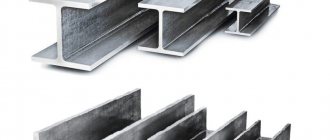
Metal floor beams are made of high-strength steel alloy using hot or cold rolling technology. Structurally, they are presented in the form of an I-beam, channel or angle, with I-beams having the greatest demand and popularity. Laying is possible both “flat” and on the edge.
Advantages:
- spans of greater length are permissible than when using wooden beams;
- resistance to biological influences and decay;
- fire resistance.
Flaws:
- high price;
- corrosion is possible;
- low sound and heat insulation parameters;
- installation requires special equipment.
Reinforced concrete beams
Reinforced concrete floor beams are the best option for large-scale construction, capable of withstanding even significant external loads over a long span. Load parameters are presented at a very high level.
Advantages:
- no deflections;
- increased load-bearing capacity;
- formation of long spans with various shapes.
Flaws:
- complexity of installation;
- the need to use specialized equipment.
Combined beams
The combined beam is made on the basis of several materials at once, for example, wood and OSB. Their use is widespread in private construction when creating frame houses. Products can have different shapes, but the most common is the combined I-beam, which can effectively resist various kinds of external loads, withstanding even significant stresses.
Advantages:
- excellent strength data;
- resistance to deformation;
- light weight.
Flaws:
- high price;
- inconvenience of insulation with slab material.
Misformation errors
The following points can be considered the main errors during the installation process::
- Use of low-quality materials in work . Here, the durability of the arrangement of layers will be a big question, since the geometry of the floor surface will be disrupted. The attic covering will have dents. New renovation will be required. Therefore, you should not skimp on materials. It is better to buy consumables from trusted manufacturers who provide a guarantee for their products.
- Unsealed seams and loose joints between insulation . They will lead to the formation of additional air flows, the appearance of cold bridges, and detachment of insulator slabs. High-quality sealing of seams and strong installation with adhesive is required, as well as the use of tubular insulating seams and a special hermetic seal.
Incorrect sequence (broken technology) of laying layers (not according to plan) .
During operation, the attic covering will quickly wear out, which, moreover, will poorly retain heat or promote the formation of condensation, which will lead to a “wet ceiling effect” indoors.You need to do everything slowly, or trust construction specialists.
- Laying layers without creating ventilation between them .
After some time, condensation and changes in atmospheric temperature can contribute to the formation of mold even in the most mold-resistant materials. In addition, some insulation materials will deteriorate and go out of use and will not be able to fully perform their function. The same applies to the absence of a vapor barrier membrane layer in a cold attic. Therefore, be sure to pay attention to this factor during installation. In the work, tools are used to measure the distance from the roof to the sheathing. - Unfinished waterproofing layer . This is one of the important points in arranging layers of cold and warm attics, which protects the main covering from the accumulation of condensation or rain if, for example, leaks have formed on the roof. Therefore, waterproofing is a prerequisite for installing attic coverings. Here, they most often use sheets or rolls of roofing felt on bitumen mastic, which are even wrapped around timber and joists.
When installing layers, the main thing that builders should pay attention to is a strong base (subfloor), as well as reliable fastening of the wooden beams and joists. To which the rest of the structure will be attached (lathing, insulation).
If there is a hatch in the attic, it is strengthened, waterproofed, insulated and finished in the same way as the main attic surface.
Technical characteristics - how not to make a mistake when choosing
Wooden beams are effective when covering a span of 2.5-4 m. The maximum length is 6 m; for longer lengths, it is necessary to install support columns or other structures.
The rafters are attached to the wooden floor beams using steel plates, angles and sliding supports. When determining the cross-section, a total load of 350-400 kg/m2 is taken as the standard for reinsurance. The optimal ratio of height and width of the product is 1.4:1. The required length of wooden floor beams is determined by the size of the span that they will cover; in addition, you need to take into account the size of the edges on the wall - at least 12 cm, for timber - at least 15 cm.
The width of the board for the beam varies from 4-20 cm, the height is 10-30 cm, the diameter of the logs can reach 11-30 cm. Depending on the dimensions of the beam, the laying step is 0.3-1.2 m (usually 0. 6-1 m).
The distance between metal floor beams ranges from 1-1.2 m. The number (size) of the beam with a load of 400 kg/m2 is selected based on the length of the span being constructed and the laying step. So, with a span of 6 m and a pitch of 1-1.2 m, 20 I-beams are optimal (height 20, width 10 cm); span 4 m, step 1-1.2 m - No. 12 (height 12, width 6.4 cm); span 3 m, step 1-1.2 m - No. 10 (height 10, width 5.5 cm).
A modern concrete floor beam can cover an opening 3-7.5 m long, and installation is carried out in increments of 1-1.5 m. The minimum element height is 1/20 of the span length, the width is calculated based on the proportion 5:7 (5 - width, 7 - height).
The sizes of combined type floor beams can be very different. For the W series, the maximum length is 6 m, the L category provides a length of up to 13.5 m. The main difference between the groups is the type of timber. In the first case, it is a planed product that has undergone chamber drying; in the second, it is glued floor beams connected from individual elements using a special technology, which gives the final product increased rigidity, strength and reliability.
Types of wooden floors at home
Wooden floors can be divided into several types according to their purpose and the material used.
By purpose:
- A wooden interfloor floor that is required to provide not only strength, but also comfort in a living space, and therefore is filled with soundproofing materials. The bottom is sheathed with plasterboard, and the top is covered with floor covering.
- An attic floor with wooden or metal beams can be either an independent structural element or part of the roof truss system and must have vapor and heat insulation layers to prevent cooling of the residential floors located underneath.
- Basement and basement floors, which have a high level of strength, as they will bear a large load. They are equipped with layers of thermal insulation and vapor barrier, as they separate the living floors from the cold basements.
By type of material:
- Made from solid wood, which is made from solid wood, mainly coniferous wood. They can only be used if the span to be covered does not exceed five meters.
- Glued - made from laminated wood. They combine strength with aesthetics. They have a smooth surface, as a result of which they can be left open at the bottom. And their strength allows them to cover significant spans.
The cross-section of wooden floor elements can be rectangular (board, timber) or round (log).
Characteristics of quality materials:
Whatever type of floor beams are used for installation, they must meet certain requirements:
- strength to static and dynamic influences, i.e. must be resistant to the loads provided for by the building design, having a margin of stability;
- rigidity that does not allow deflections and vibrations and ensures high-quality coverage of the floor above them and the ceilings below them;
- durability, since it is almost impossible to replace them during the period between planned major repairs of the entire building;
- provide sufficient heat and sound insulation;
- profitability - the use of inexpensive but high-quality material, minimal labor investment and small dimensions while meeting all technical requirements.
The parameters of the floors are selected based on the requirements for the building under construction. Currently, due to the development of private construction, wood flooring is very popular. Let's look at their design and how you can make them yourself.
In order to determine how many wooden beams and what sizes will be required for the floor installation, you must:
- measure the span that they will cover;
- decide on ways to secure them on the walls (to what depth they will go into the walls);
- make a calculation of the load that will act on them during operation;
- using tables or a calculator program, select the appropriate pitch and section.
Now let's look at how this can be done.
Length of wooden floor beams
The required length of floor beams is determined by the size of the span that they will cover and the margin required to embed them in the walls. The length of the span is easy to measure using a tape measure, and the depth of embedding in the walls largely depends on their material.
In houses with brick or block walls, beams are usually embedded in “sockets” to a depth of at least 100 mm (board) or 150 mm (timber). In wooden houses, as a rule, they are laid in special notches to a depth of no less than 70 mm.
When using special metal fastenings (clamps, angles, brackets), the length of the beams will be equal to the span - the distance between the opposite walls on which they are fastened.
Sometimes, when installing roof rafters directly on wooden beams, they are extended outward, beyond the walls by 30-50 cm, thus forming a roof overhang.
The optimal span, which can overlap wooden beams, is 2.5-4 m.
The maximum length of a beam made of edged boards or timber, that is, the span that it can cover, is 6 m. For longer spans (6-12 m), it is necessary to use modern wooden beams made of laminated veneer lumber or I-beams, and you can also rest them on intermediate supports (walls, columns). In addition, to cover spans longer than 6 m, wooden trusses can be used instead of beams.
Determination of the load acting on the floor
The load acting on the floor along wooden beams consists of the load from the own weight of the floor elements (beams, inter-beam filling, lining) and permanent or temporary operational load (furniture, various household devices, materials, weight of people). It usually depends on the type of floor and its operating conditions.
The exact calculation of such loads is quite cumbersome and is carried out by specialists when designing the floor, but if you want to do it yourself, you can use its simplified version given below.
For an attic wooden floor that is not used for storing things or materials, with light insulation (mineral wool or others) and lining, the constant load (from its own weight - Rown) is usually taken within 50 kg/m2.
The operational load (Rexpl.) for such an overlap (according to SNiP 2.01.07-85) will be:
70x1.3 = 90 kg/m2 , where 70 is the standard load value for this type of attic, kg/m2, 1.3 is the safety factor.
The total design load that will act on this attic floor will be:
Rtot.=Rown.+Rexpl. = 50+90=130 kgm 2 . Rounding up we take 150 kg/m2.
If the design of the attic space will use heavier insulation, material for inter-beam filling or lining, and also if it is intended to be used for storing things or materials, that is, it will be used intensively, then the standard load value should be increased to 150 kg/ m2. In this case, the total load on the floor will be:
50+150x1.3 = 245 kg/m2 , rounded to 250 kg/m2.
When using attic space to construct an attic, it is necessary to take into account the weight of floors, partitions, and furniture. In this case, the total design load must be increased to 300-350 kg/m2.
Due to the fact that an interfloor wooden floor, as a rule, includes floors in its design, and the temporary operational load includes the weight of a large number of household items and the maximum presence of people, it must be designed for a total load of 350 - 400 kg/m 2.
Section and pitch of wooden floor beams
Knowing the required length of wooden floor beams (L) and determining the total design load, you can determine their required cross-section (or diameter) and laying step, which are interconnected. It is believed that the best is a rectangular section of a wooden floor beam, with a ratio of height (h) and width (s) of 1.4:1. The width of the beams, in this case, can be in the range of 40-200 mm, and the height 100-300 mm. The height of the beams is often chosen so that it corresponds to the required thickness of the insulation. When using logs as beams, their diameter can be in the range of 11-30 cm.
Metal floors: production and installation
The technology of monolithic formwork manufacturing has a number of advantages compared to prefabricated formwork. Such structures are 15-20% stronger and lighter than prefabricated analogues, which increases seismic resistance, reduces the cost of the foundation and reduces the overall construction time.
When constructing buildings from monolithic formwork, designers get rid of multiple sizes and restrictions on the shape of surfaces, and receive additional opportunities for creativity. High quality materials make it possible to obtain walls and ceilings that are almost ready for finishing.
In the practice of manufacturing panel building formwork, this method is in many cases the only effective one. For example, the construction of tunnels and various hydraulic structures.
An important advantage is the transfer of the main production process to the construction site. The main elements in this case are the production of concrete mixtures and the installation of monolithic, panel formwork for walls and ceilings.
Metal floors are used as building elements for the construction of buildings of various types, including multi-level apartments and private multi-storey buildings. Using various types of metal floor beams, you can achieve significant savings on construction costs, without compromising the overall strength of the structure. In addition, such steel products weigh much less than their analogues, and their installation is carried out very quickly - this reduces the price of the product and significantly reduces the project implementation time.
Overlapping of the second level in an apartment + installation price from 112,000 rub./t Order
Ceiling beams in an apartment (with installation) price from RUB 89,400/t Order
Ceiling from metal structures in the showroom (with installation) price from 105,000 rub./t Order
Flooring in a private house (with installation) price from 91,100 rub./t Order
School floor beams (production only) price from RUB 62,000/t Order
Ceiling covering for a building price from RUB 81,500/t Order
Node calculations
All these types and other components of metal structures go through the design stage. That is, the calculation of all its main elements and details, I provide examples on my long-standing first website in the category calculation of metal structures, where you can look for my solutions. And it doesn’t matter what kind of production, industrial, public or agricultural building is designed from such solutions.
You may also be interested
Roof trusses over the assembly hall
A local engineering firm requested the service of developing CM drawings for metal roof structures. A typical
Checking the Column Base
The management of the design organization asked for a service. The goal, as it turned out, was to perform strength tests with calculations
Types and features of metal floors
Metal structures for floors are manufactured in several types, depending on their purpose of use. The choice depends, first of all, on the purpose of the building - a large industrial premises, a multi-level apartment, a house, or just a temporary structure.
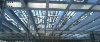
1. Floors made of rolled metal
Although such metal floors are considered universal, they are most often used in the construction of large objects, usually for industrial purposes. The I-section ensures uniform load distribution and high rigidity, so the design of floors for industrial facilities can be carried out with allowances for increased pressure on the floors of the upper floors.
Such options are universal in that there is a wide selection of rental types, depending on the intended purpose of use. The varieties most often used are cold- or hot-rolled steel or expanded metal sheets.
2. Floors with load-bearing steel beams
Such metal floors are quite simple both in manufacturing and installation. Strength is ensured by adhering to existing standards for material rigidity, as well as the rules for load distribution. Any type of flooring can be easily laid on these metal floor structures, and the structures themselves can be welded or rolled, depending on the application.
Steel beams are widely used in the construction of high-rise buildings with large areas. The use of such material increases the efficiency of creating a building and makes it possible to widely use opportunities for the implementation of non-standard projects, since beams, unlike, for example, reinforced concrete slabs, are more convenient for work.
3. Monolithic metal floor beams
This option is a set of beams on top of which sheets of a certain profile are laid. The use of various options for lattice trusses instead of beams allows you to reduce the overall weight of the structure, which is very suitable for building houses or remodeling apartments. When installing floors in an apartment, you can count on overall savings in building materials and, first of all, concrete and reinforcing material without saving on strength.
The production of floor beams in the form of monolithic structures makes it possible to achieve a high degree of rigidity with low weight, and this technology allows you to operate with many types of profile shapes. Considering that the ceiling design in an apartment may imply different degrees of load on the floors of the upper floors, this option is very popular for residential premises.
Advantages and disadvantages of metal floors
Metal floors, which have recently been manufactured using modern technologies, are distinguished by their high strength and ease of installation. Unlike classic concrete or wooden ones, such options allow you to reduce the cost of building materials, since with increased technical characteristics they are much smaller in volume and easier to manufacture.
It is especially worth highlighting metal floors, which are installed in residential buildings or multi-level apartments. As a rule, such premises have a non-standard layout, especially if we talk about such a popular project as the construction of lofts. Wooden options may be unacceptable for one reason or another, and reinforced concrete ones are not at all convenient to install for rooms with an unusual design and layout. That is why metal floors have gained great popularity in this area of use.
Among the shortcomings, one can single out almost the only one - building codes require fire protection for such elements. However, this requirement is not a particular problem and all manufacturers can not only coat products with fire-resistant alloys, but also provide anti-corrosion protection, which will significantly increase the service life of building structure elements.
Types and types of wooden floors
According to their purpose, wooden floor beams are divided into the following types:
- basement;
- attic;
- interfloor.
You should familiarize yourself with each of the subspecies in more detail.
Basement
The structure must have high strength indicators and withstand significant forces, because the beams will serve as the basis for the floor. If the design of a residential building includes a basement or a garage for a car, then the wooden blocks are replaced with metal supporting structures. This is due to the rapid destruction of wood from exposure to high humidity. An alternative option is to reduce the distance between the floor beams and treat the wooden elements with an antiseptic.
Attic
The ceiling is installed independently or is a continuation of the roof rafter system. The first option has the best technical characteristics. It is more rational to arrange an independent ceiling; such a design improves the sound insulation performance of the entire house and is considered repairable.
Interfloor
The design of floor beams in a frame house has its own characteristics. One side of the wooden beam is used as support elements for fastening the ceiling, the second (upper part) is used as a joist for installing the floor covering. The space between the interfloor beams is filled with mineral wool or other heat-insulating material; a vapor barrier membrane is mandatory. Plasterboard sheets are fixed at the bottom of the pie, and a plank wooden floor is laid on top.
Metal floors
MK Monteko LLC designs and manufactures metal floors for industrial and residential buildings, public and administrative buildings. The designs offered by the company are characterized by high strength and reliability, low weight and high installation speed. Calculation of metal floors is carried out in accordance with the current regulatory framework; high-quality rolled metal is used as blanks. If necessary, anti-corrosion treatment and coating with fire-resistant compounds are performed. The finished product meets the requirements of all technical regulations for the safety of buildings and structures.
Metal floors from MK Monteko company
Interfloor floors are most in demand today for frame buildings for various purposes. The company will manufacture all metal structures for such floors in accordance with designs or registered organization standards (STO). At the same time, production capabilities allow us to work on any project without any technical restrictions. If there is no project, then the necessary calculation of metal floors will be carried out by the company’s specialists, and metal structures will be manufactured in accordance with it. The company produces the following types of metal floors for frame buildings:
Steel interfloor ceilings made of rolled metal
- A universal type of floors between floors, basements, attics and the corresponding floor, most often used in the construction of industrial buildings. A wide range of serial products makes it possible to easily design a floor designed for the installation of various equipment. The MK Monteko company will manufacture the floor exactly according to the design; compliance with the requirements of tolerance standards and GOST standards for welding guarantees the accuracy of the assembly and the reliability of the floor structure. If necessary, instead of rolled I-beams, welded I-beams or trusses of our own production can be used.
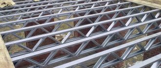
Interfloor metal ceilings made from LSTK profile
This type of flooring, which is becoming increasingly popular, is used mainly in individual housing construction, the construction of compact retail buildings and entertainment venues. It is based on a complex of profiles made of galvanized steel up to 2 mm thick; the connection of frame elements is carried out with self-tapping bolts. A profiled sheet is laid on top of the frame and then the floor can be installed. The ceiling in this design is suspended, mounted on a special “hat” profile (named after the shape of the section). With high strength, the floor frame is rigid and, in general, can withstand loads of more than 500 kg.
Floors with load-bearing steel beams
During the process of repairing or reconstructing a building, it may be necessary to replace existing floors or divide the space into several floors. This issue can be solved by using metal structures, by installing rolled and welded steel beams; any flooring can be laid on top of them or a concrete screed can be made. We will take care of all the production and calculation of floors and structural elements.
All types of metal structures assemblies I design
Attaching the posts to the foundation
Basically, hard work in one direction, and in the other, for significant savings, it is already pliable. And to eliminate this disadvantage, connections are used in this plane that split all the racks. The calculation boils down to determining the thickness of the base plate with or without stiffening ribs, as well as checking the tensile strength of the anchor bolts. An exception is the base with traverses, which requires additional testing of the anchor tiles and traverses for bending. Other checks are the load-bearing capacity of the welds and the strength of the anchor plate sections
| Rigid column base | |
| Installed in the outer rows of the building. The profile is rectangular for optimal performance. Namely, it perceives wind load in one direction. Used for one-story buildings in frame-braced systems | |
| This is a unique case that does not require absolutely connecting elements. Absolutely stable in both directions. Also used in one-story buildings | |
| The main column of multi-story or high-rise industrial buildings. From the plane it must be fastened with a system of connections for stability. Without additional ribs, the base plate will be thicker according to calculations | |
| I-beam type “B” facilitates metal consumption in the presence of lifting equipment for high objects. It has a developed cross-section in height, which reduces movement. In such cases, the support has increased bending moments, which is why the base with traverses is designed. Which usually extend beyond the anchor plate | |
Compliant connections are used when the racks are provided with stability due to the system of metal frame connections. The thickness of the plate is generally used intuitively and constructively, and the bolts are selected based on the shear conditions!
| Articulated strut support | |
| This type is apparently valid only for half-timbered racks and industrial buildings | |
| They are used in fully connected systems of small-sized one-story houses. (Project frame tent hangar) | |
Connecting main beams to columns
We construct similar assemblies of metal floor structures for multi-story construction. And also for one-story buildings, but I use them exclusively with profile rentals.
| Flexible beam-column interfaces | |
| Standard, simple way to attach a floor structure |
| More reliable due to the longer length of the weld, but requires additional spacer between the beam and the column for free installation. The downside is the higher consumption of sheet metal and labor intensity. | |
| Beam-column frame connection | |
| I use the only method of a rigid interface, I think it optimally combines reliability and aesthetics | |
Building Cover Purlins
There is no testing of the strength of the nodes, so the main thing is to select the structural connecting parts and the diameter of the bolts, which is usually M16. Exceptions are small and long-span buildings, where additional efforts may be required in purlins and connections!
| I use it exclusively for sandwich panels. Profile pipe works well for oblique bending | |
| With sandwich panels and also with profiled flooring, the ridge purlins are connected to each other by strips. In addition, sandwiches require additional tightening for their stable operation. |
Frame bracing elements
The calculation of such nodes is reduced, for medium-sized structures, to determining the section by flexibility, as well as checking the load-bearing capacity of the bolts
| The connection is adjacent to the wall of the I-beam and for some rigidity from horizontal load it is necessary to install additional ribs | |
| The emphasis goes directly to the I-beam wall and in this option there is no need for additional parts. | |
| A special feature of this solution is the presence of an additional end plate, which serves to distribute pressure with a thin-walled profile pipe | |
| The connecting plate must penetrate the transverse pipe to transmit longitudinal forces through it, which usually arise from the action of wind |
Floor beams
Strength testing consists of checking bolts for shear and crushing, as well as the strength of welds
| A common type when the channel is attached to the gusset through bolts, without additional plates | |
| Due to the fact that the transverse force transmitted from the I-beam is greater than from the channel. There is a need to use reinforced connection. This problem can be solved by welding an additional plate with significant thickness |
Roof trusses
These components of metal structures are very important. Calculation is necessary to determine the thickness of the flange plate and the diameter of the bolts
| Connections of shipping marks of coating trusses | |
| The most popular main node of the truss is the junction of the lower chord | |
| For light types of truss structures, the following coupling is used, which I generally developed independently. Suitable for lower profile sections 80 and 100mm. (Project frame tent hangar) | |
I no longer use standard truss junction units in my projects!
| Supporting a truss on a column | |
| I use a type of assembly that I developed myself, which ensures the transfer of longitudinal forces to the rack. The goal is to reduce the effort on the rack structure and its base. | |
| Another option for long-span trusses, here there are already I-beam columns | |
| Movable fastening of the half-timbered post to the truss | |
| Oval holes are necessary to compensate for the deflection of the roof truss | |